
VTOL.2500 General requirements on systems and equipment function
n/a
(a) Requirements VTOL.2500, VTOL.2505 and VTOL.2510 are general requirements applicable to systems and equipment installed in the aircraft, and should not be used to supersede any other specific SC VTOL requirement.
(b) Equipment and systems required to comply with type certification requirements, airspace requirements or operating rules, or whose improper functioning would lead to a hazard, must be designed and installed so that they perform their intended function throughout the operating and environmental limits for which the aircraft is certified.
MOC 1 VTOL.2500(b) Intended function of systems and equipment
n/a
1. Considerations on Safety Assessment and Development Assurance
(a) Compliance with VTOL.2500(b) is intrinsically linked with VTOL.2510 and should therefore be addressed simultaneously.
(b) In particular, the safety assessment and development assurance processes described in paragraph §9 and §10 of MOC VTOL.2510 are part of the accepted means of compliance with VTOL.2500(b).
2. Operating and environmental conditions
VTOL.2500(b) covers the equipment and systems installed to meet a regulatory requirement, or whose improper functioning would lead to a hazard. Such systems and equipment are required to “be designed and installed so that they perform their intended function throughout the operating and environmental limits for which the aircraft is certified”. The aircraft operating and environmental conditions include:
(c) the full normal envelope of the aircraft, as defined by the Aircraft Flight Manual, with any modification to that envelope associated with abnormal or emergency procedures;
(d) any anticipated external aircraft environmental conditions:
(1) external environmental conditions such as atmospheric turbulence, HIRF, lightning, and precipitation, which the aircraft is reasonably expected to encounter, with severities limited to those established by certification standards and precedence;
(e) any anticipated internal aircraft environmental conditions:
(1) the environmental effects within the aircraft, including vibration and acceleration loads, variations in fluid pressure and electrical power, and fluid or vapour contamination due to either the normal environment or accidental leaks or spillage and handling by personnel; and
(f) any additional conditions where equipment and systems are assumed to “perform their intended function.”
For lift/thrust system, compliance with VTOL.2400 can be used to support the compliance demonstration with VTOL.2500(b) regarding the Electric Hybrid Propulsion System (EHPS) scope defined in the Special Condition E-19 EHPS.
MOC 2 VTOL.2500(b) Electromagnetic compatibility
n/a
1. Introduction and scope
This MOC provides an accepted means of compliance related to Electromagnetic Compatibility (EMC) between different equipment and also between equipment and its interconnecting cabling. It is applicable to VTOL capable Aircraft in Categories Basic and Enhanced.
2. Electromagnetic compatibility
Electromagnetic compatibility tests should be conducted on the ground and in- flight as necessary. Any electromagnetic interference (EMI) noted on the ground should be repeated in- flight at the frequency at which the EMI occurred on the ground, unless the problem could be analysed and resolved beforehand. Since some systems are difficult to operate on the ground (e.g. air data system, etc.), the effects of EMI should be evaluated with all systems operating in- flight to verify that no adverse effects are present in the engine, energy supply system control, battery management, brake antiskid and other systems.
When electromagnetic interference and radio frequency interference (EMI and RFI) protection is required, special attention should be paid to the termination of individual and overall shields. Back shell adapters that are designed for shield termination, connectors with conductive finishes, and EMI grounding fingers are available for this purpose as are many other suitable solutions.
Electromagnetic interferences can exist between systems, but also between wires, and between wires and systems. Electromagnetic interference can be introduced into aeroplane systems and wiring by coupling between electrical cables or between cables and coaxial lines or other aeroplane systems. The correct functioning of systems should not be affected by EMI generated by adjacent wires. EMI between wiring which is a source of EMI and wire susceptible to EMI increases in proportion to the length of parallel runs and decreases with greater separation. Wiring of sensitive circuits that may be affected by EMI should be routed away from other wiring interference or provided with sufficient shielding to avoid system malfunctions under operating conditions. Regardless of the function performed, the equipment and its interconnecting wiring will unavoidably generate and be exposed to various types of electrical transients, electrical and magnetic fields, and spurious noise, spanning over a wide range of frequencies and amplitudes. For sure, EMI should be limited to negligible levels in wiring related to systems that are necessary for continued safe flight, landing and egress. A comprehensive victim and source testing is typically expected to ensure the proper functioning of the systems on the aircraft (unless another way is agreed with the Agency). The following sources of interference should be considered:
(a) Conducted and radiated interference caused by electrical noise generation from apparatus connected to the busbars.
(b) Coupling between electrical cables or between cables and aerial feeders.
(c) Parasitic currents and voltages in the electrical distribution and grounding systems, including the effects of lightning currents or static discharge.
(d) Different frequencies between electrical generating systems and other systems.
EUROCAE ED-248 is an accepted means of compliance with VTOL.2500(b) concerning electromagnetic compatibility, except that the note in its Table 3, paragraph 6.2, for helicopters or small aircraft with HF radio transmitters installed does not apply to VTOL capable aircraft.
MOC 3 VTOL.2500(b) Airworthiness Security in the Category Enhanced
n/a
Airworthiness Security is the protection of the airworthiness of an aircraft from intentional unauthorised electronic interaction: harm due to human action (intentional or unintentional) using access, use, disclosure, disruption, modification, or destruction of data and/or data interfaces. This also includes the consequences of malware and forged data and of access of aircraft systems from ground systems but does not include physical attacks or electromagnetic disturbance.
Improper functioning of equipment and systems can be caused by intentional unauthorised electronic interaction (IUEI). The applicant should consider cybersecurity threats as possible sources of ‘improper functioning’ of equipment and systems:
(a) The equipment, systems and networks of Category Enhanced VTOL capable aircraft, considered separately and in relation to other systems, should be protected from intentional unauthorised electronic interactions that may result in catastrophic or hazardous effects on the safety of the aircraft. Protection should be ensured by showing that the security risks have been identified, assessed and mitigated as necessary.
(b) When required by paragraph (a), the applicant should make procedures and instructions for continued airworthiness (ICA) available that ensure that the security protections of the aircraft equipment, systems and networks are maintained.
AMC 20-42 – Airworthiness Information Security Risk Assessment is an accepted means of compliance with VTOL.2500(b) for Airworthiness Security aspects.
MOC 4 VTOL.2500(b) Certification credit for simulation and rig tests
n/a
1. Scope of this MOC
This MOC provides methods and guidance when using simulation benches and test rigs in the substantiation of compliance with different system requirements of the SC-VTOL (for example: VTOL.2500(b), VTOL.2510, VTOL.2135, etc.).
In this MOC:
(a) ‘simulation bench’ refers to a simulator with pilot in the loop capability, when “Simulation” has been agreed in the Certification Programme as the means to demonstrate compliance with a requirement in the SC-VTOL (See Appendix A to AMC 21.A.15(b)).
(b) ‘test rig’ refers to a laboratory test bench, when “Laboratory test” has been agreed in the Certification Programme as the means to demonstrate compliance with a requirement in the SC VTOL (See Appendix A to AMC 21.A.15(b)).
Other uses of simulation benches and test rigs are out of scope from this particular MOC, in particular with different purposes than defined under (a) and (b) (e.g. when supporting an assessment if “Calculation/Analysis” has been agreed in the Certification Programme to demonstrate compliance with a requirement in the SC VTOL, or when they are not in connection with the type certification exercise). Moreover, this MOC does not apply to the compliance demonstration of structural requirements of Subparts C and D.
This MOC is intended as a general guideline that should be applied to any rig tests or simulations when fulfilling the purposes defined under (a) and (b). Additional and specific guidelines for using rig tests to show compliance with specific requirements (e.g. VTOL.2520) may be available in the MOCs associated to these requirements.
2. Introduction
For most aircraft, simulator benches and test rigs commonly used to support aircraft integration tests may also support some certification tests. This requires particular attention on complex, highly integrated aircraft: simulators and test rigs are efficient and powerful means that enable the evaluation of failure cases which sometimes could even not be tested by flight test. Indeed, traditional verification methods are usually effective for loss of function, but additional effort is often needed for more complex aspects (e.g. malfunction, unintended behaviour, cascading failures/faults, propagation effects, common mode errors). Furthermore, simulator benches and test rigs also offer flexibility to perform the evaluations with different scenarios and enable to check the impact of parameters’ variability. Tests on simulators and test rigs may be agreed in the Certification Programme to show compliance with some certification requirements, particularly for Handling Qualities (HQ), Performance, Flight Controls and other systems, as well as for Human Factors (HF). This MOC may thus apply to any simulator or rig test facilities when proposed to be used as a means of compliance or to support a means of compliance (e.g. failure case evaluation to support a safety analysis) for certification requirements.
To ensure that credit can be taken from simulators and test rigs tests, simulators and test rigs should be adequately representative of aircraft systems and flight dynamics. At the same time, the limitations for using simulators and test should be established. This objective can be achieved by a combination of a controlled development process of simulators and test rigs, simulator configuration management, system models behaviour validation (crosschecked when necessary with partial system development bench or flight test results, analysis, desktop simulation) and engineering/operational judgment.
3. Means of Compliance
To qualify simulation benches and test rigs so that they can be used to substantiate compliance for certification, the following aspects should be addressed by the applicant:
(a) Identify/list all simulator benches and test rigs proposed in the Certification Programme to be used for “simulation” and “laboratory test” compliance demonstrations (as per Appendix A to AMC 21.A.15(b)).
(b) Controlled development process:
Simulation benches and test rigs usually integrate numerous real aircraft systems or components, and modelled systems or components. Although simulation benches and test rigs are not subject to certification, the design of such devices for use as a certification means is deemed of sufficient complexity to stipulate a formalized and structured development process.
(1) Simulation benches and test rigs specifically developed to support a given certification project should have a formalized and structured development process to achieve the applicant’s own objectives for the scope and intended use.
This development process should include the usage of problem reports to record identified issues and their associated corrections (see Section 3(c)(2))
(2) When simulation benches and test rigs are re-used from another project, the applicant should propose justifications to ensure the correctness/appropriateness of the rigs for the intended purpose.
(c) Configuration management:
(1) Simulation benches and test rigs configuration should be managed similarly to the test aircraft configuration with a traceability that covers all relevant systems and models as well as the human machine interface (HMI). A change control process should also be implemented.
(2) A detailed status of simulation benches and test rigs should be established for all certification tests (including tests performed without Agency participation) and briefed along with each test order before the certification tests:
(i) The configuration management of simulation benches and test rigs should include the relevant elements for the test objectives (e.g. version of the flight control laws/software, flightcrew alerting system and the electronic check list (ECL)
(ii) Problem reports should be established and assessed at system test level for their effects on the representativeness in all relevant aspects (e.g. Human Factor, Handling Qualities, System Performances). This would typically include deficiencies, process deviations and errors in definition or implementation of simulation benches or test rigs.
(3) The tracking and impact assessment of the models’ limitations (see section 4 below) and any simulation bench problem reports should be part of the configuration management process.
(4) Consistency of the simulation benches and rig tests design with aircraft design:
As part of the configuration management process, the consistency of the aircraft design with simulation benches and test rigs should be guaranteed. The objective is to ensure:
(i) The representativeness of the benches with respect to the expected certification configuration; In case modifications are performed once the certification tests have started, the simulation benches or test rigs modification impact analysis should assess the need for additional/modified testing (e.g. new/updated tests, regression tests).
(ii) The identification of the impact of post-test evolutions of the aircraft design on the validity of the certification tests performed on the simulation benches and test rigs.
(iii) The repeatability of the tests later on
(d) Representativeness:
(1) The applicant should provide an overview of the general verification strategy applied for the integration of the different systems and models in simulation benches and test rigs:
Integration testing should begin with item-by-item integration building to intra-system, inter-system and aircraft level integration, using verification at each stage. The intent is not for the Agency to verify each step of the integration or over-formalise this process but to share an understanding of this process (and where it is documented) in order to obtain confidence in the representativeness of the simulation bench.
(i) Similarly, for each major simulation bench configuration change, an integrated verification is necessary and should also follow a similar controlled process.
(ii) The intent of the bench should be defined (e.g. test(s) intended to be performed, validation of a procedure) and depending on the intent, the representativeness for the part/scope that is required should be demonstrated.
(2) For an agreed “Simulation” compliance demonstration: the certification evaluations performed in the simulation bench are typically with an aircraft-level view, they cover not only the aircraft behaviour or a single item or system but possibly multiple systems as well as the flight crew procedures and the workload. The demonstration of the representativeness and limitations of the simulator bench should, therefore, also be at aircraft-level, that is inter--systems. Representativeness of simulated failure cases should also be demonstrated. The representativeness and limitations should match the test objectives and be synthetised in a single document.
(3) For an agreed “Laboratory test” compliance demonstration: the certification evaluation performed on a test rig may be with a system, multi-system, or aircraft-level view. The representativeness and limitations should match the test objectives and be synthetized in a single document.
(4) The representativeness demonstration:
(i) Should cover the steady state and the transient phases and should be based on flight test data when available, as proposed by the applicant.
(ii) Where (i) is not possible, for instance for hazardous or catastrophic failure cases, the demonstration should also include analysis (for example, matching of system behaviour expected by the design office with the simulator bench/test rig behaviour) and comparison with partial or segmented demonstration of a failure case performed in flight when relevant.
(iii) For the system part, qualification test data, partial system bench or flight test results combined with analysis and/or engineering judgement could also be used to assess the system response compared to the related models embedded in the simulation bench.
(5) The representativeness and limitations assessment should also cover the dynamics of data exchanges between systems during the failures and the potential dynamics (including time delays) introduced by the specific hardware and model architecture of the simulation bench and test rig, when the timing may influence the sequence of events and the system/aircraft behaviour.
(6) Models’ representativeness and limitations:
(i) For system models, when used instead of the real aircraft systems:
(A) the representativeness and limitations of these models should be established and presented before the evaluation, and
(B) this status in (A) should include the functional and/or operational impacts due to the lack of representativeness or the limitations, and
(C) these pieces of information in (B) should be part of the configuration management mentioned in Section 3.(c) of this MOC.
(ii) The representativeness and limitations (in terms of flight domain for instance) of the simulated aircraft dynamics and the aerodynamic models (including on aircraft the control surfaces hinge moments and free-float positions):
(A) should be demonstrated (by comparison to flight test data when available) and documented, and
(B) relevant tolerances specified in the applicable certification specification for flight simulation training devices may be used as a guideline, and
(C) sound engineering judgment should be exercised to determine whether tolerances of the models are adequate.
(iii) When used to support VTOL.2510 compliance demonstration, the simulation bench:
(A) should be capable of monitoring structural loads during tests through a model, and
(B) if no real time monitoring is available, the simulation bench test data could be post-processed when high load level are suspected, and
(C) the representativeness and the limitations of aircraft loads models used should be established.
(iv) Aircraft on the ground model representativeness and limitations should be part of this status.
Note: This status on models’ representativeness and limitations should be established and briefed before the certification tests.
(7) When the performance impact is an expected output of a failure case assessment in the simulation bench,
(i) the representativeness and limitations should be documented (e.g. ground effect, ground reaction and braking models), and
(ii) point (i) should be supported by a combination of flight test results, analysis, desktop simulation and engineering/operational judgment to provide a qualitative/reasonable assessment of the performances’ representativeness, and
(iii) depending on the intended evaluation, the most appropriate simulator bench configuration (i.e., using models versus real systems) may vary. This choice should be justified, documented, and briefed before the evaluation.
(8) For Human Factors assessments,
(i) the representativeness of systems and simulation means is not a key driver in the early stages of the development and should not necessarily prevent simulation bench usage as long as the nature of the limitations does not compromise the validity of the data to be collected.
(ii) partial certification credit may still be granted while using a non-conformed test article, provided that the item to be evaluated is simulated with an adequate level of representativeness.
(9) When the simulation bench is used for purposes of Human Factors and Handling Qualities evaluation certification,
(i) the simulation bench should be designed to maximise the subject pilots' immersive environment to demonstrate and validate the Human Factor data.”
(ii) it is recommended to ensure a sterile environment (no outside noise or visual perturbation), with realistic simulation of ATC communications, subject pilots wearing headsets, etc.
(10) For Human Factors (HF) and Handling Qualities (HQ) evaluation certification tests, the applicant should present the list of problem reports and simulation bench limitations. Their related cockpit effects with an assessment of their impacts on the representativeness of the certification exercise should be presented to the Agency. Problem reports that are considered to not affect the HF and HQ evaluations by either comparison to Flight Test data, Analysis or Engineering Judgement do not need to be presented to the Agency. Regardless of Agency attendance or not to HF or HQ evaluations, this data is expected to be directly visible in the certification data package, for example data could be included in the evaluations test reports.
(e) Recognition of the simulation bench in the design organisation manual (or equivalent) as a certification means:
If the simulation bench is planned to be used to generate compliance data (this applies for instance if some certification tests are planned to be performed on the simulation bench or test rigs):
(1) For any test facility used to produce deliverables (e.g. certification reports), the personnel and the processes should be managed via procedures under the control of the Design Organization.
(2) The simulation bench should be recognized as an asset of the applicant Design Organization.
(3) The applicant should document:
(i) how the simulation bench is recognized in the Design Organisation Manual (or equivalent) as a certification mean;
(ii) which processes of the Design Organization are in place that are related to the aspects and considerations discussed in this MOC.
(f) Automatic testing and analysis tools
(1) Automatic testing and analysis tools, if used, should be subject to a controlled development process (see Section 3.(b)) and configuration management (see Section 3.(c)). This includes automatic testing and analysis tools that are not considered to be part of the simulation and test rigs but are used to process the associated verification data.
(2) Pass/fail criteria should be reviewed and
(i) should take care of the bench and system dynamics, and
(ii) special care should be taken if static or quasi-static criteria are used, and
(iii) a manual review of the critical cases (e.g. safety-critical monitors, reconfigurations after failure) should still be performed to identify if the dynamic of the parameters used to compute the pass/fail criteria are correct, or to detect unexpected behaviours outside the direct parameters under analysis.
(3) If the automatic testing or analysis tool eliminates, reduces, or automates processes for this simulation bench, then the tool should be qualified to a way acceptable to the Agency. For example, guidance from ED-215/DO-330 Software Tool Qualification Considerations for TQL-5 may be followed.
(4) Limitations and problem reports should be recorded, and
(i) their impact should be assessed as part of the configuration management process, and
(ii) a process to address these limitations needs to be established and could include identification of temporary corrective actions (e.g. manual review) pending correction.
VTOL.2505 General requirements on equipment installation
n/a
(a) Each item of installed equipment must be installed according to limitations specified for that equipment.
(b) Reserved.
VTOL.2510 Equipment, systems, and installations
n/a
(a) The equipment and systems identified in SC VTOL.2500, considered separately and in relation to other systems, must be designed and installed such that:
(1) each catastrophic failure condition is extremely improbable and does not result from a single failure;
(2) each hazardous failure condition is extremely remote; and
(3) each major failure condition is remote.
(b) The operation of equipment and systems not covered by SC VTOL.2500 must not cause a hazard throughout the operating and environmental limits for which the aircraft is certified.
(c) For Category Enhanced, provisions for in-service monitoring of equipment and systems which failure may have hazardous or catastrophic consequences must be established.
MOC VTOL.2510 Equipment, systems, and installations
n/a
1. Purpose
This MOC describes an accepted means for showing compliance with the requirements VTOL.2510(a) and VTOL.2510(b). These means are intended to supplement the engineering and operational judgement that should form the basis of any compliance demonstration.
Whilst this MOC details “what” should be addressed for showing compliance with the requirement VTOL.2510(a), it does not provide detailed guidance on the implementation of development assurance and safety assessment processes. Detailed guidance and recommended practices may be found in the standards that are recognised through the list of reference documents in §3 below.
In general, the extent and structure of the analyses required to show compliance with VTOL.2510(a) and VTOL.2510(b) will be greater when the system is more complex and the effects of the Failure Conditions are more severe.
2. Applicability
As specified in VTOL.2500(a), paragraph VTOL.2510 is intended as a general requirement that should be applied to any equipment or system as installed, in addition to specific systems requirements, considering the following:
(a) General - If a specific SC VTOL requirement exists which predefines systems safety aspects (e.g., redundancy level or criticality) for a specific type of equipment, system, or installation, then the specific SC VTOL requirement will take precedence. This precedence does not preclude accomplishment of a system safety assessment. For example, requirement VTOL.2430 predefines a required level of redundancy in the energy storage and distribution systems.
(b) Subpart B, C and D - While VTOL.2510 does not apply to the performance and flight characteristics of Subpart B and structural requirements of Subparts C and D, it does apply to any system on which compliance with any of those requirements is based. For example, it does not apply to an aircraft's inherent stall characteristics, but it does apply to a stall warning system used to enable compliance with VTOL.2150.
(c) Subpart E - In certain VTOL configurations, the lift/thrust system is closely integrated with other systems, such as the flight control system, and will also affect “continued safe flight and landing” or the “controlled emergency landing”. Therefore the “lift/thrust control systems” and “lift/thrust system installation hazard assessment” will be addressed through the requirements VTOL.2500 and VTOL.2510 of Subpart F.
This MOC does not cover “Airworthiness Security” aspects. Interactions and interfaces between the system safety assessment process and the security assessment process exist however. Therefore, should a function be implemented or a system/equipment installed on the aircraft as a result of the airworthiness security assessment process, this function or system/equipment needs to undergo the system safety assessment process.
3. Reference Documents
The following references are quoted in different sections of this MOC as a source of additional guidance:
(a) EUROCAE ED-79A/ARP4754A, Guidelines for development of civil aircraft and systems
(b) SAE ARP4761, Guidelines and methods for conducting the safety assessment process on civil airborne systems and equipment.
(c) AMC 20-115( ), Airborne Software Development Assurance Using EUROCAE ED-12 and RTCA DO-178.
(d) AMC 20-152( ), Development Assurance in Airborne Electronic Hardware (AEH)
(e) AMC 20-189( ), Management of Open Problem Reports.
(f) AMC 25-19 Amdt. 24, Certification Maintenance Requirements
4. Definitions
(a) Complexity: An attribute of functions, systems or items which makes their operation, failure modes or failure effects difficult to comprehend without the aid of analytical methods. (Source: ED-79A/ARP4754A).
(b) Continued Safe Flight and Landing: see MOC to VTOL.2000 Applicability and definitions.
(c) Controlled emergency landing: see MOC to VTOL.2000 Applicability and definitions.
(d) Commercial-Off-The-Shelf (COTS) software: Commercially available applications that are sold by vendors through public catalogue listings. COTS software is not intended to be customised or enhanced. Contract-negotiated software developed for a specific application is not COTS software (Source: ED-12C/DO-178C).
(e) Derived requirements: Additional requirements resulting from design or implementation decisions during the development process which are not directly traceable to higher-level requirements and/or specify behaviour beyond that specified by the higher level requirements (Source: adapted from ED-79A/ARP4754A and ED-12C/DO-178C).
(f) Development Assurance: All of those planned and systematic actions used to substantiate, at an adequate level of confidence, that errors in requirements, design and implementation have been identified and corrected such that the system satisfies the applicable certification basis. (Source: ED-79A/ARP4754A).
(g) Development Assurance Level (DAL): the level of rigor of development assurance tasks necessary to demonstrate compliance with paragraphs VTOL.2500 and VTOL.2510 (Source: adapted from ED79A/ARP4754A). The DALs are determined by the system safety assessment process.
Two types of development assurance levels are identified in this document:
(1) FDAL: Development Assurance Levels for aircraft functions, systems and equipment
(2) IDAL: Development Assurance Levels for software and electronic hardware items
(h) Error: An omission or incorrect action by a flight crew member or maintenance personnel, or a mistake in requirements, design, or implementation.
Note: Errors may cause failures, but are not considered to be failures (Source: adapted from AMC 25.1309 in Book 2 of CS-25 Amdt. 24).
(i) Event: An occurrence which has its origin distinct from the aircraft, such as atmospheric conditions (e.g. gusts, temperature variations, icing and lightning strikes) , runway conditions, conditions of communication, navigation, and surveillance services, bird-strike, payload fire. The term is not intended to cover sabotage. (Source: adapted from AMC 25.1309 in Book 2 of CS-25Amdt. 24)
(j) Failure: An occurrence that affects the operation of a component, part, or element such that it can no longer function as intended (this includes both loss of function and malfunction). (Source: adapted from AMC 25.1309 in Book 2 of CS-25 Amdt. 24)
(k) Failure Condition: A condition having an effect on the aircraft, its occupants and/or third parties, either direct or consequential, which is caused or contributed to by one or more failures or errors, considering flight phase and relevant adverse operational or environmental conditions, or external events. (Source: adapted from AMC 25.1309 in Book 2 of CS-25 Amdt. 24)
(l) Latent failure: A failure is latent until it is made known to the flight crew or maintenance personnel. (Source: adapted from AMC 25.1309 in Book 2 of CS-25 Amdt. 24)
(m) Malfunction: Failure of a system, subsystem, unit, or part to operate in the normal or usual manner. The occurrence of a condition whereby the operation is outside specified limits. (Source: AC 23.1309-1E)
(n) Open-source software: describes software that comes with permission to use, copy and distribute, either as is or with modifications, and that may be offered either free or with a charge. The source code should be available. (Source: Gartner)
(o) Significant latent failure: A significant latent failure is one, which would in combination with one or more specific failures, or events result in a Hazardous or Catastrophic Failure Condition. (Source: adapted from AMC 25.1309 in Book 2 of CS-25 Amdt. 24).
5. Abbreviations
(a) AEH – Airborne Electronic Hardware
(b) COTS – Commercial Of The Shelf
(c) CMA – Common Mode Analysis
(d) (F)/(I)DAL – Function / Item Development Assurance Level
(e) PRA – Particular Risk Analysis
6. Principles of Fail-Safe design concept
The requirements of SC-VTOL incorporate the objectives and principles or techniques of the fail-safe design concept, which considers the effects of failures and combinations of failures in defining a safe design.
(a) The following basic objectives pertaining to failures apply:
(1) In any system or subsystem, the failure of any single element, component, or connection during any one flight should be assumed, regardless of its probability. Such single failures should not be catastrophic.
(2) Subsequent failures of related systems during the same flight, whether detected or latent, and combinations thereof, should also be considered.
(b) The fail-safe design concept uses the following design principles or techniques in order to ensure a safe design. The use of only one of these principles or techniques is seldom adequate. A combination of two or more is usually needed to provide a fail-safe design, i.e. to ensure that major failure conditions are remote, hazardous failure conditions are extremely remote, and catastrophic failure conditions are extremely improbable:
(1) Designed Integrity and Quality, including Life Limits, to ensure intended function and prevent failures.
(2) Redundancy or Backup Systems to enable continued function after any single (or other defined number of) failure(s); e.g. two or more engines, hydraulic systems, flight control systems, etc.
(3) Isolation and/or Segregation of Systems, Components, and Elements so that the failure of one does not cause the failure of another.
(4) Proven Reliability so that multiple, independent failures are unlikely to occur during the same flight.
(5) Failure Warning or Indication to provide detection.
(6) Flight Crew Procedures specifying corrective action for use after failure detection.
(7) Checkability: the capability to check a component's condition.
(8) Designed Failure Effect Limits, including the capability to sustain damage, to limit the safety impact or effects of a failure.
(9) Designed Failure Path to control and direct the effects of a failure in a way that limits its safety impact.
(10) Margins or Factors of Safety to allow for any undefined or unforeseeable adverse conditions.
(11) Error-Tolerance that considers adverse effects of foreseeable errors during the VTOL capable aircraft’s design, test, manufacture, operation, and maintenance.
7. Failure conditions classifications and probability terms
(a) Failure Conditions Classifications.
Failure Conditions are classified according to the severity of their effects as follows:
(1) No Safety Effect: Failure Conditions that would have no effect on safety; for example, Failure Conditions that would not affect the operational capability of the aircraft or increase crew workload.
(2) Minor: Failure Conditions which would not significantly reduce aircraft safety, and which involve crew actions that are well within their capabilities. Minor Failure Conditions may include, for example, a slight reduction in safety margins or functional capabilities, a slight increase in crew workload, such as routine flight plan changes, or some physical discomfort to passengers.
(3) Major: Failure Conditions which would reduce the capability of the aircraft or the ability of the crew to cope with adverse operating conditions to the extent that there would be, for example, a significant reduction in safety margins or functional capabilities, a significant increase in crew workload or in conditions impairing crew efficiency, physical distress to occupants, possibly including injuries, or physical discomfort to the flight crew.
(4) Hazardous: Failure Conditions, which would reduce the capability of the aircraft or the ability of the crew to cope with adverse operating conditions to the extent that there would be:
(i) a large reduction in safety margins or functional capabilities, or
(ii) physical distress or excessive workload such that the flight crew’s ability is impaired to where they could not be relied on to perform their tasks accurately or completely, or
(iii) for Category Enhanced, possible serious injury to an occupant other than the flight crew, but no fatality reasonably expected, or
(iv) for Category Basic, serious or fatal injury to an occupant other than the flight crew.
(5) Catastrophic:
(i) For Category Enhanced, failure conditions, which are expected to result in one or more fatalities, or incapacitation of a flight crew member, usually with the loss of the aircraft. Failure conditions that would prevent continued safe flight and landing of the aircraft are also considered catastrophic.
(ii) For Category Basic, failure conditions, which are expected to result in multiple fatalities, or incapacitation or fatal injury to a flight crew member, usually with the loss of the aircraft. Failure conditions that would prevent a controlled emergency landing of the aircraft are also considered catastrophic.
|
Explanatory Note: The Categories Basic and Enhanced were introduced in the Special Condition to allow proportionality in safety objectives. The highest safety levels of Category Enhanced apply for the protection of third-parties when flying over congested areas or when conducting commercial air transport of passengers. Different levels of performance are also requested through the performance objectives of Continued Safe Flight and Landing and of Controlled Emergency Landing. This issue of the MOC adds considerations for incapacitation, serious injuries and fatalities in the definitions of Hazardous and Catastrophic failure conditions. For Category Basic, the definitions are similar to AC 23.1309-1E. For Category Enhanced fatalities are excluded in the definition of Hazardous failure conditions due to the high number of operations anticipated and the public safety expectations in the air taxi/urban air mobility context. This also aligns with the expected approach for RPAS where a fatality (on the ground) would be classified Catastrophic. |
When referring to “fatalities”: passengers, flight crew and people on ground are considered.
(b) Qualitative Probability Terms.
When using qualitative analyses to determine compliance with VTOL.2510(a), the following descriptions of the probability terms used in VTOL.2510 and this MOC have become commonly accepted as aids to engineering judgment:
(1) Probable Failure Conditions are those that are anticipated to occur one or more times during the entire operational life of each aircraft.
(2) Remote Failure Conditions are those that are unlikely to occur to each aircraft during its total life, but which may occur several times when considering the total operational life of a number of aircraft of the type.
(3) Extremely Remote Failure Conditions are those that are not anticipated to occur to each aircraft during its total life but which may occur a few times when considering the total operational life of all aircraft of the type.
(4) Extremely Improbable Failure Conditions are those so unlikely that they are not anticipated to occur during the entire operational life of all aircraft of one type.
The objective of VTOL.2510(a) is to ensure an acceptable safety level for equipment and systems as installed on the aircraft. A logical and acceptable inverse relationship must exist between the average probability per flight hour and the severity of failure condition effects.
(a) Safety Objectives per aircraft category and failure condition classification:
The safety objectives for each failure condition are:
|
|
|
Failure Condition Classifications |
|||
|
Maximum Passenger Seating Configuration |
Minor |
Major |
Hazardous |
Catastrophic |
|
|
Allowable Qualitative Probability |
|||||
|
Probable |
Remote |
Extremely Remote |
Extremely Improbable |
||
|
|
Allowable Quantitative Probability (Note C and D) Development Assurance Level |
||||
|
Category Enhanced |
- |
≤ 10-3 FDAL D (see Note B) |
≤ 10-5 FDAL C |
≤ 10-7 FDAL B |
≤ 10-9 FDAL A |
|
Category Basic |
7 to 9 passengers (Basic 3) |
≤ 10-3 FDAL D (see Note B) |
≤ 10-5 FDAL C |
≤ 10-7 FDAL B |
≤ 10-9 FDAL A |
|
2 to 6 passengers (Basic 2) |
≤ 10-3 FDAL D (see Note B) |
≤ 10-5 FDAL C |
≤ 10-7 FDAL C (see Note A) |
≤ 10-8 FDAL B (see Note A) |
|
|
0 to 1 passenger (Basic 1) |
≤ 10-3 FDAL D (see Note B) |
≤ 10-5 FDAL C |
≤ 10-6 FDAL C (see Note A) |
≤ 10-7 FDAL C (see Note A) |
|
|
[Quantitative safety objectives are expressed per flight hour] |
|||||
Note A: no considerations of the system architecture for a DAL reduction are acceptable, as the FDAL classification already constitute a proportionate approach.
Note B: Alleviation in software development assurance for IDAL D as per section 10(c) is possible.
Note C: It is recognised that, for various reasons, component failure rate data may not be precise enough to enable accurate estimates of the probabilities of Failure Conditions. This results in some degree of uncertainty. When calculating the estimated probability of each Failure Condition, this uncertainty should be accounted for in a way that does not compromise safety.
Note D: The applicant is not expected to perform a quantitative analysis for minor failure conditions.
Note E: An average flight profile (including flight phases duration) and an average flight duration should be defined.
(b) Single failure and common cause failure considerations:
According to VTOL.2510(a)(1), a catastrophic failure condition must not result from the failure of a single component, part, or element of a system. Failure containment should be provided by the system design to limit the propagation of the effects of any single failure to preclude catastrophic failure conditions. In addition, there must be no common-cause failure, which could affect both the single component, part, or element, and its failure containment provisions. A single failure includes any set of failures, which cannot be shown to be independent from each other. Common-cause failures (including common mode failures) and cascading failures should be evaluated as dependent failures from the point of the root cause or the initiator. Errors in development, manufacturing, installation, and maintenance can result in common-cause failures (including common mode failures) and cascading failures. They should, therefore, be assessed and mitigated in the frame of the common –cause and cascading failures consideration.
Protection from multiple failures should be provided when the first failure would not be detected during normal operations of the aircraft, which includes pre-flight checks.
Sources of common cause and cascading failures include development, manufacturing, installation, maintenance, shared resource, event outside the system(s) concerned, etc. The ARP4761 describes types of common cause analyses, which may be conducted, to ensure that independence is maintained (e.g. particular risk analyses, zonal safety analysis, common mode analyses), see also Section 9(b).
While single failures should normally be assumed to occur, experienced engineering judgment and relevant service history may show that a catastrophic failure condition by a single failure mode is not a practical possibility. The logic and rationale used in the assessment should be so straightforward and obvious that the failure mode simply would not occur unless it is associated with an unrelated failure condition that would, in itself, be catastrophic.
Analyses should always consider the application of the fail-safe design concept as described in section 6, and give special attention to ensuring the effective use of design techniques that would prevent single failures or other events from damaging or otherwise adversely affecting more than one redundant system channel or more than one system performing operationally similar functions
Early coordination with the Agency on these aspects is advised.
(a) Overview
The Safety Assessment process aims at demonstrating that systems and components are designed and installed in a way that occurrence probabilities of failure conditions are commensurate with their classification and that no catastrophic failure condition results from a single failure. It consists of several objectives, listed below in no particular order:
(1) Examine aircraft and system functions to identify potential functional failures and classify the hazards associated with specific failure conditions.
(2) Establish the safety requirements for the aircraft, its systems and items and validate these safety requirements.
(3) Verify that system architecture and design meets the corresponding safety requirements and the safety objectives, including the single failure criterion.
(4) Establish and verify physical and functional separation, isolation and independence requirements between systems and items, and verify that these requirements have been met.
Guidance on how to perform the Safety Assessment process can be found in ED-79A/ARP4754A and ARP4761. The applicant may propose other guidance for the Safety Assessment process, which should be agreed with the Agency in conjunction with the overall proposed Development Assurance process.
The depth and scope of the analyses are dependent on the system criticality and/or complexity.
The safety assessment process is an iterative process, requiring preliminary assessment steps to ensure that the proposed system architecture(s) can reasonably be expected to meet the safety objectives, as well as regular coordination with the Agency on the different process steps.
When identifying the aircraft and system functions and classifying the hazards associated with the Failure Conditions, the applicant will have to substantiate the effects of failure conditions with consideration to operational conditions and events. Guidance on the handling qualities assessment can be found in MOC VTOL.2135.
Any assumptions made during the safety assessment process need to be justified and validated.
(b) Common mode considerations
Common mode analysis (CMA) is an analytical method to define independence principles and associated requirements, and verify that those independence requirements have been implemented sufficiently. The CMA serves also as a tool to identify any lack of independence and to develop mitigation means to reduce the likelihood or the effect of a common mode failure resulting from a lack of independence.
The CMA should be performed early in the safety assessment process, because it has an impact on the definition of the safety requirements as well as on the system architecture.
Sources of common mode failures include development, manufacturing, installation, maintenance, shared resource, event outside the system(s) concerned, etc. When identifying mitigation means for specific common modes, the means should be appropriate to the common mode failure/error.
It is important to note that even Items that are developed to IDAL A may be subject to development error. Such error may simultaneously affect several instances of the same item with potential functional or safety consequences. EASA has experienced cases, where a development error in IDAL A item has even resulted in simultaneous failures of all affected equipment. Therefore, it should not be assumed that IDAL A items are protected from such development errors and consequently they should be included in the scope of the common mode analysis irrespective of the FDAL/IDAL of the system/item.
The following structured approach is accepted to accomplish a common mode analysis:
(1) Establish program-specific checklists (for common mode types, sources, and resulting failures/errors). ARP4761 paragraph K.3.1 can be followed for this purpose. These checklists should be used to detect elements that may defeat the redundancy or independence principles within the design.
The following Common Modes are examples of common mode types, sources, and resulting failures/errors to be considered:
(i) Software development errors
(ii) Hardware development errors
(iii) Hardware failures
(iv) Production/repair flaws
(v) Stress related events (e.g., abnormal flight conditions, abnormal system configurations)
(vi) Installation errors
(vii) Requirement errors
(viii) Environmental factors (e.g., temperature, vibration, humidity, etc.)
(ix) Cascading faults
(x) Common external source faults
(xi) General Common Modes are further detailed in the ARP4761 table K1.
(2) Identify the independence principles and requirements. ARP4761 paragraph K.3.2 can be followed for this purpose.
These Failure Conditions should cover both the availability (i.e. loss) and integrity of functions and protections.
(3) Analyse the design to ensure it meets the principles and requirements identified in paragraph (2) above. ARP4761 paragraph K.3.3 can be followed for this purpose.
The analysis of the design:
(i) should be conducted not just at system level but also at item level (Airborne Electronic Hardware items including architecture and Software items including architecture), and
(ii) should address both the availability (i.e. loss) and integrity of functions and protections.
(4) Document the results of the above steps of the CMA process. ARP4761 paragraph K.4 can be followed for this purpose.
Additional considerations may be appropriate for some specific systems and functions. In particular for Fly-by-wire Flight Control Functions, MOC 4 VTOL.2300 applies.
10. Development Assurance process
Any analysis necessary to show compliance with VTOL.2510(a) should consider the possibility of development errors.
For simple systems, which are not highly integrated with other aircraft systems, errors made during the development of systems may still be detected and corrected by exhaustive tests conducted on the system and its components, by direct inspection, and by other direct verification methods capable of completely characterising the behaviour of the system. Such items may be considered as meeting the DAL A rigor when they are fully assured by a combination of testing and analysis, however requirements for these items should be validated with the rigor corresponding to the FDAL of the function. Systems which contain software and/or complex electronic hardware items, cannot be considered simple.
For more complex or highly integrated systems, exhaustive testing may either be impossible because all of the system states cannot be determined or impractical because of the number of tests which should be accomplished. For these types of systems, compliance may be shown by the use of development assurance. The level of development assurance should be commensurate with the severity of the failure conditions the system is contributing to.
(a) Development Assurance Level (DAL) allocation
The development assurance level of a function or of an item is assigned depending on the classification of the failure conditions it contributes to.
Initial FDAL allocation is performed in accordance with Section 8(a) in this MOC.
Guidelines, which may be further used for the allocation of development assurance levels to aircraft and system functions (FDAL) and to items (IDAL), are described in the document ED-79A/ARP4754A, section 5.2.
In the absence of agreed guidelines on FDAL/IDAL allocation, the FDAL should be commensurate with those applicable to the category of aircraft as per Sectionn8(a) in this MOC and the IDAL of all components contributing to a given function should be equal to the FDAL of that function.
(b) Aircraft/System development assurance
For the aircraft and for systems of FDAL A, B, C or D, this MOC recognises the ED-79A/ARP4754A as acceptable guideline for establishing a development assurance process from aircraft and systems levels down to the level where software/ Airborne Electronic Hardware (AEH) development assurance is applied.
The extent of application of ED-79A/ARP4754A to substantiate functional development assurance activities may vary depending on the complexity of the systems and on their level of interaction with other systems. Early concurrence with the Agency is essential.
(c) Software development assurance
This MOC recognises AMC 20-115( ) as an accepted means of compliance with requirement VTOL.2510(a).
For Commercial-Off-The-Shelf (COTS) software items and open-source software, in addition to the provisions of AMC20-115(), this MOC recognises guidance from DO-278A/ED-109A section 12.4 as an alternative that could be generally applied beyond the limits of CNS/ATM systems. In this case, the association between ED-12C/DO-178C software level and ED-109A/DO-278A AL (Assurance Level) can be found in DO-278A / ED-109A table 2-2 of section 2.3.3 ‘Assurance Level Definitions’.
Alleviation for software items of IDAL D contributing to Minor Failure Conditions:
(1) For Category Basic 1 and Basic 2 (c.f. Table 1: Safety Objectives), it is possible to alleviate the software-level development assurance, relying on system-level development assurance processes, provided that:
(i) the equipment is one piece of equipment; and
(ii) the equipment is developed with an acceptable development assurance process.
(2) For Category Basic 3 (see Table 1: Safety Objectives) and Enhanced, the software-level development assurance may be alleviated provided that:
(i) the software high-level requirements are defined and are verified to be captured in the systems requirements as described in ED-79A/ARP4754A section 5.4; and
(ii) if some are ‘derived requirements’, a mechanism is in place to properly identify, validate and verify those derived software high-level requirements as described in ED-79A/ARP4754A section 5.4.
Note: In both cases, the system-level processes are not considered to be software development assurance processes.
(d) Airborne Electronic Hardware development assurance
This MOC recognises AMC 20-152( ) as accepted means of compliance for requirement VTOL.2510(a).
(e) Open Problem Report management
This MOC recognises AMC 20-189( ) as accepted means of compliance for establishing an open problem report management process for the system, software and AEH domains.
(f) Considerations on derived requirements
ED-79A/ARP4754A section 5.3.1.4 adequately addresses the concerns related to potential for errors introduced by derived requirements while designing and implementing the systems
However, if ED-79A/ARP4754A section 5.3.1.4 defines the derived requirements as those that “may not be uniquely related to a higher-level requirement “, the definition could create an ambiguity as it is limited to “Additional requirements resulting from design or implementation decisions during the development process which are not directly traceable to higher-level requirements”.
Requirements that trace to a higher-level requirement and add a behaviour that is not specified at a higher level should also be considered as derived.
As a consequence, the definition from ED-79A/ARP4754A is superseded by the definition provided in Section 4 of this document.
11. Considerations for highly integrated systems
(a) Generic guidance
(1) When aircraft functions are provided by a combination of systems, the relevant requirements of those systems should be validated together, including the following activities:
(i) Analysis of the potential interactions and interferences between systems,
(ii) Planning of dedicated activities at system and aircraft levels to ensure validation of those requirements that are affected by interactions or interference.
(2) When incorporating multiple functions into the same system or equipment, applicability of AMC 20-170 should be considered. For architectures with no partitioning, particular care should be taken in the analysis of interactions between functions.
(b) Additional Considerations for the Lift/Thrust system
For most VTOL capable aircraft designs, the Flight Control System and the Lift/Thrust system are highly integrated, i.e. the propulsion system directly contributes to the controllability of the aircraft. Therefore the development of the Lift/Thrust system should take into consideration the safety objectives of Section 8 and should follow the provisions of VTOL.2510 and associated guidance.
12. Latent failure considerations
The use of periodic maintenance or flight crew checks to detect significant latent failures when they occur is undesirable and should not be used in lieu of practical and reliable failure monitoring and indications. Significant latent failures are latent failures that would, in combination with one or more specific failure(s) or event(s), result in a Hazardous or Catastrophic failure condition and should be avoided in system design.
Within the frame of the no single failure criterion, dual failure combinations, with either one latent, that can lead to a Catastrophic Failure Condition should be avoided in system design. Any such combinations should be highlighted in the relevant SSA and discussed with the Agency as early as possible after identification.
Additional considerations may be appropriate for some specific systems and functions. In particular for Fly-by-wire Flight Control Functions, MOC 5 VTOL.2300 applies.
13. Flight Crew and Maintenance considerations
(a) Flight Crew actions
When assessing the ability of the flight crew to cope with a failure condition, the information that is provided to the flight crew and the complexity of the required action should be considered. If the evaluation indicates that a potential failure condition can be alleviated or overcome during the time available without jeopardizing other safety related flight crew tasks and without requiring exceptional pilot skill or strength, credit may be taken for correct and appropriate corrective action for both qualitative and quantitative assessments. Similarly, credit may be taken for correct flight crew performance if overall flight crew workload during the time available is not excessive and if the tasks do not require exceptional pilot skill or strength. Unless flight crew actions are accepted as normal airmanship, the appropriate procedures should be included in the Agency-approved AFM or in the AFM revision or supplement. The AFM should include procedures for operation of complex systems such as integrated flight guidance and control systems. These procedures should include proper pilot response to cockpit indications, diagnosis of system failures, discussion of possible pilot-induced flight control system problems, and use of the system in a safe manner.
(b) Maintenance actions
Credit may be taken for the correct accomplishment of maintenance tasks in both qualitative and quantitative assessments if the tasks are evaluated and found to be reasonable. Required maintenance tasks, which mitigate hazards, should be provided for use in the Agency-approved ICA. Annunciated failures that will be corrected before the next flight or a maximum duration should be established before a maintenance action is required. If the latter is acceptable, the analysis should establish the maximum allowable interval before the maintenance action is required. A scheduled maintenance task may detect latent failures. If this approach is taken, and the failure condition is hazardous or catastrophic, then a maintenance task should be established. The process for the identification and selection of these scheduled maintenance tasks requires early coordination and agreement with the Agency. Guidance may be found in AMC 25-19.
Credit could be given to tests performed due to mean time between failures (MTBF) to detect the presence of hidden failures, if it can be ascertained that the equipment is removed and inspected at a rate much more frequent than the safety analysis requires. This credit should be substantiated in the relevant SSA. The means of detection of the hidden failures should be clearly identified, either at the opportunity of the acceptance tests performed before the equipment enters service or leaves the manufacturer, or at the opportunity of test of system integrity when it is installed back on the aircraft. This substantiation should be recorded in the relevant SSA. In case of double failures, with either one or both hidden, that can lead to Catastrophic or Hazardous Failure Condition, no credit should be taken from MTBF for failure detection, and the maintenance task enabling detection of the hidden failure should be identified as a required maintenance task.
MOC VTOL.2510(a) Aircraft Parachute Rescue System
n/a
1. Scope of this MOC
(a) This MOC provides guidance and methods for addressing the installation and operation of Aircraft Parachute Rescue Systems (APRS). An APRS is intended to prevent serious injuries to the occupants and third parties, during an impact onto the ground while the aircraft is suspended beneath a fully inflated parachute system, following a serious in-flight incident.
(b) The MOC is applicable to VTOL capable aircraft in the Categories Basic and Enhanced.
(c) The purpose of this MOC is to offer a path for demonstrating compliance with SC-VTOL of an APRS installation intended as a last resort following a failure classified as catastrophic and already meeting the corresponding probability target as per MOC VTOL.2510, without taking any credit for the APRS. Therefore, APRS installations cannot be:
(1) used for substantiation or relief of requirements defined in SC-VTOL,
(2) part of the minimum equipment,
(3) compensation for any deviation from SC-VTOL.
2. Background
Aircraft Parachute Rescue Systems (APRS) are designed to provide a last safety resort in case of a partial or full loss of aircraft controllability. A variety of system concepts are available, a number of them have been tested successfully, and some have eventually been certified together with the aircraft design.
Common to all of them are parachute canopies made from textile fabric, lines, connecting bridles and a deployment system. Textile decelerators, parachutes are a sub-group of them, have a longstanding and successful history. The current technology covers the range of any combination from very low speed to high Mach numbers, light payload to tons of heavy payload and from low to high altitude [1].
Nevertheless, the engineer’s task remains challenging as the design needs to be tailored to the specific use. Furthermore, the interaction between the forebody wake and parachute system in all phases from deployment to landing depends highly on the design of the aircraft. Last, but not least, parachutes are made from fabric, the behaviour of which changes each time the same sample is tested.
Thusly, a certain margin in performance and reliability needs to be taken into account.
Furthermore, an efficient APRS requires two further elements, the suspension system and the crashworthiness of the aircraft fuselage. The suspension system connects the aircraft structure to the bridle line. It should assure a predefined attitude for touchdown, despite reasonably expectable damages to the aircraft structure. The crashworthiness of the aircraft fuselage is intended to dissipate and consume the impact energy such that the occupants suffer no serious injuries. It is obvious, that the effectivity of the crashworthiness depends on the correct attitude at initial touchdown with the ground.
Last, but not least, the demonstration of the function under realistic conditions is required. The APRS can be demonstrated for a certain Capability Category. The four available categories ⋆, ⋆⋆, ⋆⋆⋆, ⋆⋆⋆⋆ depend on the scope of the demonstrated scenarios and to what extent this has been shown by flight or ground test (see Chapter 5., Table 2).
This MOC VTOL.2510(a) is based on research data, existing standards (see Chapter 3.) and certification of parachute systems (see Chapter 4., Table 1) for General Aviation aircraft. It is applicable for SC-VTOL up to the maximum certified take-off mass of 5 700 kg or less.
3. Reference documents
[1] Parachute Recovery Systems Design Manual; T.W. Knacke, January 1992, ISBN: 0-915516-85-3
[2] ASTM F3408/F3408M-20, © ASTM International, 100 Barr Harbor Drive, PO Box C700, West Conshohocken, PA 19428-2959, U.S.A.
[3] Vorläufige Ergänzungsforderungen für den Einbau von Gesamtrettungssystemen in Segelflugzeugen und Motorseglern; Luftfahrt-Bundesamt, October1994
[4] OSTIV Airworthiness Standards for Sailplane Parachute Rescue Systems, October 1996, P. Kousal for OSTIV
[5] Entwicklung von Nachweisverfahren für die Verkehrssicherheit von Segelflugzeugen und Motorseglern;
W. Röger et al., February 2002, FE-Nr. L-1/98-50169/98, FH Aachen for German Ministry of Transport
[6] Untersuchungen des Insassenschutzes bei Unfällen mit Segelflugzeugen und Motorseglern;
M. Sperber et al., 1998, L-2/93-50112/92, TÜV Rheinland for German Ministry of Transport
[7] Verbesserung der Insassensicherheit bei Segelflugzeugen und Motorseglern durch integrierte Rettungssysteme; W. Röger et al., April 1994, FE-Nr. L-2/90-50091/90, FH Aachen for German Ministry of Transport
[8] Insassensicherheit bei Luftfahrtgerät; W. Röger et al., December 1996, FE -L-4/94-50129/94, FH Aachen for German Ministry of Transport
4. EASA/FAA Publications
These MOCs have been issued as part of certification projects (in chronological order):
Table 1: EASA/FAA Publications
|
Number, Date, Authority |
Title |
Code, Aircraft |
Seats, MTOM, |
|
23–ACE–88 November 1997 FAA4See: https://www.federalregister.gov/ |
Ballistic Recovery Systems Cirrus SR–20 Installation |
Part 23 Model SR-20 |
4 seats, 1 428 kg Vc 155 KTAS, 17 500 ft |
|
CSTMG01 SC 02 May 2008 EASA5See: https://www.easa.europa.eu/document-library/product-certification-consu… |
CSTMG01 Special Condition 02 in accordance to Part 21.A.16B (a) (1): Sailplane Parachute Rescue System |
CS-22 generic (not model specific) |
2 seats, 900 kg Vc 270 km/h EAS |
|
SC-OVLA.div-01 March 2010 EASA2 |
Installation of Ballistic Recovery System (BRS) |
CS-VLA generic (not model specific) |
2 seats, 750 kg |
|
23-16-01-SC August 2016 FAA1 |
Cirrus Design Corporation, Model SF50; Whole Airplane Parachute Recovery System |
Part 23 Model SF50 |
5/7 seats, 6 000 lb Vc 250 kt, 28 000 ft |
5. Means of Compliance
For the demonstration of compliance with the Special Condition VTOL, the following Means of Compliance are accepted:
(a) ASTM standard ‘F3408/F3408M − 20, Standard Specification for Aircraft Emergency Parachute Recovery Systems’, reference [2], together with the additional requirements in (b),
(b) Supplemental requirements based on references [3] and [4], substantiated by references [5] through [8]. These are listed in Table 2 and Table 3 below:
|
Basic only |
Basic and Enhanced |
||||
|
Nr. |
Test requirement fulfilled |
⋆ |
⋆⋆ |
⋆⋆⋆ |
⋆⋆⋆⋆ |
|
i. |
Flight test deployment at vNE |
|
|
|
X |
|
ii. |
Flight test deployment in a stabilised turn at the most critical of the following combinations of bank angle and speed: - the maximum permissible bank angle at its maximum permissible speed - vH or vNE, whichever is lower, and its associated maximum bank angle |
|
|
X |
X |
|
iii. |
Flight test deployment during stabilised hover |
|
|
X (see Note 1) |
X (see Note 1) |
|
iv. |
Flight test deployment at maximum permissible vertical rate of descent (at zero forward speed) |
|
X |
X |
X |
|
v. |
Parachute drop test at maximum design altitude |
|
X |
X |
X |
|
vi. |
Parachute drop test at vNE |
X |
X |
X |
|
|
vii. |
Ground test deployment at lowest temperature |
|
|
X |
X |
|
viii. |
Ground test deployment at highest temperature |
|
X |
X |
X |
|
ix. |
Ground deployment/extraction test (zero height and speed), with increased mass of the rescue system according to maximum limit load factor n |
X |
X |
|
|
|
x. |
Static strength test of parachute attachment to the airframe up to ultimate load, considering flight speed up to vD. |
X |
X |
X |
X |
Color legend: Colour coding in Table 2 means, blue for an additional requirement, and orange for a no-longer applicable requirement when moving to the next higher Capability Category.
Note 1: Unless test requirement (iii) is shown to be less severe than (iv), both tests (iii) and (iv) should be performed for Capability Category *** and Capability Category ****.
|
Table 3: Supplemental requirements based on references [3] and [4] |
|
Compliance with requirements in ‘non-activated‘ condition |
|
The airworthiness requirements for the basic type design should be complied with to the full extent, as long as the aircraft rescue system is not activated. |
|
Opening shock |
|
Oscillation caused by the opening force should be sufficiently damped. |
|
At critical aircraft masses the parachute system should comply correspondingly with the applicable requirements of ETSO-C23f, or any equivalent acknowledged requirement. |
|
Application of opening shock into the aircraft structure |
|
All textile components of a suspension system should have at least a safety factor of 2 against failure. A possibly asymmetric loading of the suspension system should be taken into account. Precautions should be taken to prevent possible damages of the APRS due to aircraft structure damages such as sharp edges or splintering. |
|
Activation of the rescue system |
|
The design should provide sufficient margin to prevent malfunction caused by stacking up of tolerances (due to manufacturing and installation processes), temperature effect, g-load or any other conditions encountered in the operational domain. |
|
a) Manual operation of the rescue system should comply with VTOL.2510(a) and in addition should satisfy the following conditions: |
|
1) The release should be done by a handle which is pulled for activation. |
|
2) The handle should be (also under the expected acceleration conditions) well reachable and operable by pilots of differing size, by either right or left hand. |
|
3) The handle should be conspicuously colour coded and clearly marked from the other operating knobs of the aircraft. |
|
4) The handle should be large enough so that the necessary operating forces can be safely applied by the whole hand, even when gloves are worn. |
|
Example: A handle which |
|
- is located in a central position between the inceptor(s) (such as control stick or wheel) and the pilot, |
|
- has a colour coding by yellow-black rings, |
|
- is like a stiff loop handle (analogue to an ejection seat), |
|
is considered compliant with the above-mentioned requirements. |
|
b) Automatic operation of the rescue system should comply with VTOL.2510(a). |
|
c) For the activation, a combination of points a) and b) is acceptable. Nevertheless, each paragraph needs to be fully complied with. |
|
d) For points a) and b) the Flight Manual should describe in detail the required sequence of activation, the criteria for activation, the procedures to reconfigure the propulsion system in a secure manner and any related limitations and procedures, as applicable. |
|
A safety assessment should be performed to assess the effect of system normal function and functional failures. It should not only address potential hazards to the occupants and people on the ground during normal activation, but also following unintended/spurious activations. All failure conditions and their severity should be identified in line with VTOL.2510. On most aircraft, unintended/spurious activation is likely to have catastrophic effects in some phases of operation. Suitable precautions taken to ensure the system meets the safety objectives associated to these failure conditions should include all realistic conditions which occur during the |
|
- operation |
|
- rescue by first-aiders |
|
- storage |
|
- maintenance |
|
- transportation |
|
of the aircraft. |
|
b) The status ‘secured’/’armed’ should be simply and unequivocally verifiable from the inside and outside of the cockpit. |
|
Control forces and travel for the activation of the release mechanism |
|
a) The operating force necessary for the release of the system should be: - higher or equal to 10 daN, and, - lesser or equal to 20 daN. |
|
Mechanical integration of the rescue system into the aircraft |
|
The integration of all components required for the successful functioning of the rescue system should be done in an area of the aircraft, the damaging of which is improbable in case of mid-air collisions and aerial disintegration. |
|
Precautions against twisting of the parachute system |
|
Suitable means should ensure that no twisting of the parachute lines occurs due to rotation. |
|
Emissions |
|
Emissions produced by the use of the rescue system should neither lead to severe health impairment of the occupants, nor to break-out of a fire. |
|
Compliance with other requirements |
|
Compliance with these requirements should not relieve from compliance of other related requirements. For instance, regulations for handling explosives must be observed. |
|
Operating limitations and information |
|
Operating information should be furnished which define the handling of the system during |
|
- operation, |
|
- rescue by first-aiders, |
|
- storage, |
|
- maintenance, |
|
- transportation. |
VTOL.2515 Electrical and electronic system lightning protection
n/a
Unless it is shown that exposure to lightning is unlikely:
(a) each electrical or electronic system that performs a function, the failure of which would prevent continued safe flight and landing for Category Enhanced, or a controlled emergency landing for Category Basic, must be designed and installed such that:
(1) the function at the aircraft level is not adversely affected during and after the time the aircraft is exposed to lightning; and
(2) the system recovers normal operation of that function in a timely manner after the aircraft is exposed to lightning unless the system’s recovery conflicts with other operational or functional requirements of the system.
(b) each electrical and electronic system that performs a function, the failure of which would reduce the capability of the aircraft or the ability of the flight crew to respond to an adverse operating condition, must be designed and installed such that the system recovers normal operation of that function in a timely manner after the aircraft is exposed to lightning.
MOC VTOL.2515 Electrical and electronic system lightning protection
n/a
1. Unlikely Exposure to Lightning
It is stated in VTOL.2515 that sub paragraphs (a) and (b) are applicable “unless it is shown that the exposure to lightning is unlikely”. The demonstration on this condition should be based on reliable meteorological reports and/or on-board means to detect lightning, directly or indirectly (e.g. Lightning Detector, Weather Radar). Therefore, an accepted means to avoid the compliance demonstration with electrical and electronic system lightning protection requirements is to establish the following operational limitations:
(a) VFR Day with reliable weather reports stating the absence of significant clouds before and/or during the flight for departure, enroute, terminal and diversion vertiports, or
(b) VFR with means to detect lightning or storm cells via a certified onboard system, and/or ground base support plus appropriate communication with the pilot. The qualification of such ground-based system should be ensured by the operator.
When VTOL.2515 (a) and (b) are applicable, this MOC proposes simplified methods for addressing the Indirect Effects of Lightning (IEL) compliance demonstration on VTOL capable aircraft. These methods vary depending on the VTOL capable Aircraft categories; Basic 1 (0 to 1 passenger), Basic 2 (2 to 6 passengers), Basic 3 (7 to 9 passengers) and Enhanced.
2. Reference Documents
The following references are quoted in different sections of this MOC as a source of additional information or to provide accepted methods and practices:
(a) Industry Standards
(1) ASTM
|
F3061/F3061M |
Specification for Systems and Equipment in Small Aircraft |
|
F3230 |
Standard Practice for Safety Assessment of Systems and Equipment in Small Aircraft |
|
F3309 |
Standard Practice for Simplified Safety Assessment of Systems and Equipment in Small Aircraft |
(2) EUROCAE/SAE/RTCA
|
ED-81/ARP5413A |
Certification of an Aircraft Electrical/Electronic Systems for the Indirect Effect of Lightning |
|
ED-84/ARP5412B |
Aircraft Lightning Environment and Related Test Waveforms |
|
ED-91/ARP5414B |
Aircraft Lightning Zoning |
|
ED-105/ARP5416A |
Aircraft Lightning Test Methods |
|
ED-158/ARP5415B |
User/s Manual for Certification of Aircraft Electrical/Electronic Systems for the Indirect Effect of Lightning |
|
ED-14()/DO-160() |
Environmental Conditions and Test Procedures for Airborne Equipment |
(b) Authorities Guidance
(1) FAA
|
PS-ACE-23-10 |
HIRF/Lightning Test Levels and Compliance Methods for 14 CFR Part 23 Class I, II, and III Aircraft Note: only partially recognised by EASA |
|
AC 23.1309-1E |
System Safety Analysis and Assessment for Part 23 Aircraft |
|
AC 20-136B |
Aircraft Electrical and Electronic System Lightning Protection |
(2) EASA
|
Acceptable Means of Compliance for VTOL System Safety Analysis and Assessment |
|
|
AMC 20-136 |
Aircraft Electrical and Electronic System Lightning Protection |
3. Definitions
For the purpose of this MOC the following definitions apply:
(a) Actual Transient Level (ATL): The level of transient voltage or current that appears at the equipment interface circuits due to the external environment. This level may be less than or equal to the transient control level, but should not be greater.
(b) Adverse Effect: A response of a system that results in an undesirable and/or unexpected operation of an aircraft system, or undesirable and/or unexpected operation of the function performed by the system.
(c) Ceiling And Visibility are OK (CAVOK): statement in meteorological report indicating that there are no clouds below 5000 ft AGL (or Minimum Sector Altitude whichever is greater), no presence of Towering Cumulus (TCU) and/or Cumulonimbus (CB) and visibility above 10 km.
(d) Equipment: A component of an electrical or electronic system with interconnecting electrical conductors.
(e) Equipment Transient Design Level (ETDL): The peak amplitude of transients to which equipment is qualified.
(f) Hazard related to lightning exposure: Comparison between the probability to be struck by Lightning and the failure from another internal cause.
(g) IEL Group: Group of VTOL categories having the same methodology for their Indirect Effects of Lightning compliance demonstration. 3 Groups have been identified; Group I for VTOL Category “Basic 1” (0-1 passenger), Group II for VTOL Category “Basic 2” (2-6 passengers) and Group III for VTOL Categories “Basic 3” (7-9 passengers) and Enhanced.
(h) Immunity: Capacity of a system or piece of equipment to continue to perform its intended function, in an acceptable manner, in the presence of an electrical transient.
(i) Indirect effects: Electrical transients induced by lightning in aircraft electrical or electronic circuits.
(j) Internal environment: The potential fields and structural voltages inside the aircraft that are produced by the external environment.
(k) Lightning Certification Level (LCL): Level of an electrical or electronic system performing a function whose most critical Failure Condition is catastrophic, hazardous or major.
(l) Margin: The difference between the equipment transient design levels and the actual transient level.
(m) No Significant Cloud (NSC): statement where CAVOK information is not met but ensures no presence of Towering Cumulus (TCU) and/or Cumulonimbus (CB).
(n) Normal Operation: A status where the system is performing its intended function. When addressing compliance with VTOL.2515 (a) (2), the function whose failure would prevent the continued safe flight and landing for Category Enhanced or a controlled emergency landing for Category Basic should be in the same undisturbed state than before exposure to the Lightning threat. Other functions, performed by the same system, subject to VTOL.2515 (b), are not required to be recovered.
(o) System: An electrical or electronic system includes all electrical and electronic equipment, components and electrical interconnections that are required to perform a particular function.
(p) Transient Control Level (TCL): The maximum allowable level of transients that appear at the equipment interface circuits because of the defined external environment.
(q) Upset: Impairment of system operation, either permanent or momentary. For example, a change of digital or analogue state that may or may not require a manual reset.
4. Means of Compliance:
(a) Minimum Design Considerations
(1) In order to utilise the methods described in this practice, the following minimum design considerations should be addressed. If deviations from these minimum design considerations are desired, the acceptability of the methods described should be agreed by the Agency.
(2) The airframe should incorporate low impedance electrical conductors to allow lightning current to flow through the aircraft. The low impedance conductors should be incorporated into the basic structure of the aircraft.
(i) For aircraft with primarily metal structure, the metal skin provides a low impedance electrical conductor. Standard rivets and bolts should provide adequate electrical bonding between permanent structural joints. Electrical bonding straps or jumpers should be installed on moving parts or for removable panels or parts.
(ii) For aircraft with primarily carbon fibre or fiberglass structure, metal mesh, metal foil, or expanded metal foil should be incorporated onto the external surfaces of the aircraft composite structure. This mesh or foil should be joined together electrically and provide a continuous electrical conductor between the extremities of the aircraft. Metallic components that are internal to the structure of the aircraft may also be used to provide similar shielding for equipment and its wiring.
(iii) For aircraft constructed of tube and fabric, the tube skeleton can be considered to be the low impedance electrical path through the aircraft. The bonding also may be achieved by the use of bonding straps or jumpers where required to electrically bond other metallic sub-structure that might be relied upon to provide bonding for equipment.
(3) Electrical bonding specifications and verifications should be developed and implemented on the production drawings and instructions for continued airworthiness.
Additional considerations for wiring protection can be found in ED-158 A (User’s Manual for certification of aircraft electrical/Electronic Systems for the Indirect Effect of Lightning).
(b) IEL Group Determination
The IEL Group should be identified by using Table 1; the relevant Group will determine the IEL Compliance Verification method given in paragraph (d).
|
|
VTOL Categories |
|||
|
Basic (max passenger seating configuration) |
Enhanced |
|||
|
0-1 |
2-6 |
7-9 |
||
|
IEL Group |
I |
II |
III |
III |
Table 1 – IEL Group Allocation
(c) IEL Safety Assessment
(1) Aircraft systems that require an IEL Safety Assessment should be identified. The elements of the system that perform a function should be defined, considering redundant and/or backup equipment that constitutes the system. The process used for identifying these systems should be similar to the process used for showing compliance with VTOL.2510. This requirement addresses any system failure that may cause or contribute to an effect on the safety of flight of an aircraft. The effects of a Lightning Strike should be assessed to determine the degree to which the aircraft and its systems safety may be affected. The operation of the aircraft systems should be assessed separately and in combination with, or in relation to, other systems. This assessment should cover:
(i) All normal aircraft operating modes, stages of flight, and operating conditions;
(ii) All failure conditions and their subsequent effect on aircraft operations and the flight crew; and
(iii) Any corrective actions required by the flight crew.
(2) A safety assessment related to IEL should be performed to establish and classify the equipment or system failure condition. Table 2 provides the corresponding Failure Condition classification and system IEL certification level for VTOL.2515. The IEL safety assessment determines the consequences of failures, due to IEL, for the aircraft functions that are performed by the system. The Lightning Certification Level (LCL) classification assigned to the system and functions can be different from the Design Assurance Levels assigned for equipment function and/or item (software, and complex electronic hardware). This is because operation in Lightning environment can cause common cause effects. The term ‘Design Assurance Level’ should not be used to describe the Lightning Certification Level because of the potential differences in assigned classifications for software, complex electronic hardware, and equipment function
|
IEL Requirements VTOL.2515 |
MOST CRITICAL FAILURE CONDITION OF THE FUNCTION |
SYSTEM LIGHTNING CERTIFICATION LEVEL (LCL) |
|
Unless it is shown that exposure to lightning is unlikely: (a) Each electrical or electronic system that performs a function, the failure of which would prevent continued safe flight and landing for Category Enhanced, or a controlled emergencylanding for Category Basic, must be designed and installed such that: (1) The function at the aircraft level is not adversely affected during and after the time the aircraft is exposed to lightning; and (2) The system recovers normal operation of that function in a timely manner after the aircraft is exposed to lightning unless the system’s recovery conflicts with other operational or functional requirements of the system.
|
Catastrophic |
A |
|
(b) The Each electrical and electronic system that performs a function, the failure of which would reduce the capability of the aircraft or the ability of the flight crew to respond to an adverse operating condition, must be designed and installed such that the system recovers normal operation of that function in a timely manner after the aircraft is exposed to lightning. |
Hazardous/Major |
B/C |
Table 2 – IEL Failure Conditions and System Lightning Certification Level
(i) The IEL safety assessment should consider all potential adverse effects due to system failures; loss, malfunctions or misleading information caused by IEL threat. The IEL safety assessment may show some systems have different failure conditions in different phases of flight; therefore, the LCL corresponds to the most critical Failure Condition
(ii) In addressing the Failure Condition in Table 2, the nature of IEL should be considered. The potential for common cause of failures across multiple equipment/systems performing the same or different functions due to the simultaneous exposure to the IEL threat should be considered. Additionally, the inherent immunity of mechanical systems with no electrical circuitry should also be considered.
(iii) In addressing the Failure Condition in Table 2, the indirect effects of lightning should not be combined with random failures that are not the result of the IEL threat.
(iv) Due to the similar approach in the safety assessment process related to IEL and HIRF, the System Certification Levels for HIRF and Lightning are usually the same.
(d) IEL Compliance Verification
(1) Unless operational limitations are implemented to only allow operation in VFR Day with reliable weather reports on the absence of significant clouds, or the Operation in VFR is permitted with certified VTOL systems to detect the lightning strike or storm cells, then the likelihood of exposure to lightning in VMC condition has to be considered (see Figures 1 and 2 in Section 5). Nevertheless, the Hazard related to this exposure on VTOL capable aircraft could be assessed by comparing the Rate of lightning strike to Aircraft and the Safety objectives at Aircraft Level (see Table 3 in Section 5); in some cases, the probability of having a lightning strike to an aircraft is lower than the probability of having a failure from another technical cause. In such cases, the Hazard associated with a lightning strike can be considered to be unlikely and therefore for lower IEL Groups and the IEL Groups operating in VFR, VTOL.2515 (b) is not applicable for Level B and/or C systems that can be removed from the verification (see Section 6).
(2) IEL Group I
(i) For level A Systems (Display and Non-Display)
(A) Follow the AMC 20-136; or
(B) Conduct Equipment/System testing using the following categories:
(a) According to the VTOL capable aircraft primary structure and wiring type, choose the appropriate Category/Waveform at Level 3 in EUROCAE ED-14G section 22.
(b) Fail/Pass Criteria: when subjected to the Lightning Environment, it could be acceptable that equipment is/are subject to adverse effect, provided that the Level A function is maintained at the aircraft level and all the Equipment/Systems that are required in normal operation recover manually or automatically, in a timely manner, this function after the threat.
(ii) For Level B Systems on aircraft approved for IFR Operation
Conduct Equipment/System testing using the following categories:
(A) According to the VTOL capable aircraft primary structure and wiring type, choose the appropriate Category/Waveform at Level 2 in EUROCAE ED-14G 22.
(B) Fail/Pass Criteria; when submitted to the Lightning Environment, it could be acceptable that redundant equipment is/are subject to adverse effect, provided that the Level B function is recovered manually or automatically, in a timely manner, after the threat.
(3) IEL Group II
(i) For level A Systems (Display and Non-Display)
(A) Follow the AMC 20-136; or
(B) Conduct Equipment/System testing using the following categories:
(a) According to the VTOL capable aircraft primary structure and wiring type, choose the appropriate Category/Waveform at Level 3 in EUROCAE ED-14G section 22.
(b) Fail/Pass Criteria; when submitted to the Lightning Environment, it could be acceptable that equipment is/are subject to adverse effect; provided that the Level A function is maintained at the aircraft level and all the Equipment/System, required in normal operation, recover manually or automatically, in a timely manner, this function after the threat.
(ii) For Level B Systems
Conduct Equipment/System testing using the following categories:
(A) According to the VTOL capable aircraft primary structure and wiring type, choose the appropriate Category/Waveform at Level 2 in EUROCAE ED-14G 22.
(B) Fail/Pass Criteria; when submitted to the Lightning Environment, it could be acceptable that redundant equipment is/are subject to adverse effects, provided that the Level B function is recovered manually or automatically, in a timely manner, after the threat.
(4) IEL Group III
(i) For Level A Non-Display Systems:
(A) Follow the AMC 20-136; or
(B) Determine the aircraft Actual Transient Level (ATL) (by test, analysis, combination of both or by similarity); and
(C) Conduct Equipment/System testing using the following categories:
(b) Fail/Pass Criteria; when submitted to the Lightning Environment, it could be acceptable that equipment is/are subject to adverse effect, provided that the Level A function is maintained at the aircraft level and all the Equipment/Systems that are required in normal operation, recover manually or automatically, in a timely manner, this function after the threat.
(c) Verify the positive margin between the default levels applied during the Equipment/System testing (EDTL as defined in (a)) and the Transient Control Level (TCL, maximum expected aircraft ATLs). If a positive margin is not established, corrective measures should be implemented in line with AMC 20-136.
(ii) For level A Display Systems:
(iii) Conduct Equipment/System testing using the following categories:
(A) For VTOL capable aircraft with primarily metal structure, EUROCAE ED-14G section 22 category A3J3L3.
(B) For VTOL capable aircraft with primarily carbon fibre, fiberglass or non-conductive material structure, EUROCAE ED-14G section 22 category B3K3L3.
(C) Fail/Pass Criteria; when submitted to the Lightning Environment, it could be acceptable that equipment is/are subject to adverse effect, provided that the Level A function is maintained at the aircraft level and all the Equipment/Systems required in normal operation recover manually or automatically, in a timely manner, this function after the threat.
(iv) For level B Systems:
(v) Conduct Equipment/System testing using the following categories:
(A) For VTOL capable aircraft with primarily metal structure, EUROCAE ED-14G 22 category A2J2L2.
(B) For VTOL capable aircraft with primarily carbon fibre, fiberglass or non-conductive material structure, EUROCAE ED-14G section 22 category B2K2L2.
(C) Fail/Pass Criteria; when submitted to the Lightning Environment, it could be acceptable if redundant equipment is/are subject to adverse effect, provided that the Level B function is recovered manually or automatically, in a timely manner, after the threat.
(vi) For Level C Systems on aircraft approved for IFR Operation:
(vii) Conduct Equipment/System testing using the following categories:
(A) For VTOL capable aircraft with primarily metal structure, EUROCAE ED-14G 22 category A1J1L1.
(B) For VTOL capable aircraft with primarily carbon fibre, fiberglass or non-conductive material structure, EUROCAE ED-14G section 22 category B1K1L1.
(C) Fail/Pass Criteria; when submitted to the Lightning Environment, it could be acceptable that redundant equipment is/are subject to adverse effect, provided that the Level C function is recovered manually or automatically, in a timely manner, after the threat.
(5) IEL Testing for Level A Systems considerations;
(i) The Test Levels for upper IEL Group could also be used for lower IEL Group; for instance, the use of the level for Level A Non-Display System for IEL Group III can be used for Level A System of IEL Groups I/II.
(ii) Equipment testing is acceptable when it is shown that the interdependencies between equipment performing a function are understood and each equipment is tested and monitored to verify there is no unacceptable upset of the function.
(iii) If similar equipment are used to perform the same function, the test can be limited to a single equipment.
(6) Level A System architecture consideration: when a level A system is composed of redundant channels/equipment that perform the same level A function, it is permitted to limit the system to the channels/equipment that are required in normal operation provided that they are not susceptible when they comply with VTOL.2515(a); for instance if it is demonstrated that the primary channels comply with VTOL.2515(a) without the support of the back-up channel, the equipment of this channel is/are not required to be qualified to Level 3/4, however this back-up channel should be considered to be as a level B system (Level 2).
5. Rate of Lightning strike to small aircraft and Failure Condition Likelihood
(a) Rates of Lightning strike in General Aviation
Research on lightning strikes to aircraft has shown that the rate of lightning strikes per flight cycle is closely correlated to several parameters: the size, the cruise altitude and the ratio of VMC/IMC conditions. This correlation provides a method for estimating the likelihood of lightning strikes to smaller aircraft.
Table 3 provides estimated small aircraft lightning strike rates based on this correlation.
|
A/C Class |
Class I |
Class II |
Class III |
|
Percentage of operations in instrument meteorological conditions |
10% |
27% |
38% |
|
Rate of lightning strikes per flight cycle |
7. 10-6 |
2.10-5 |
7.10-5 |
|
Hours per flight cycle |
0.73 |
0.80 |
1.41 |
|
Rate of lightning strikes per flight hour |
10-5 |
3.10-5 |
5.10-5 |
Table 3 - Estimated small aircraft lightning strike rates
(b) Environmental Condition and Aircraft Position
A Lightning strike database has been established for the FAA; it compiles all the lightning strikes reports involving small aircraft.
Figure 1 shows, from this Lightning Strike database shows the position of the aircraft when it was struck by lightning. It can be seen from this figure that this mainly occurs when the aircraft is in clouds where intra-clouds flashes are intercepted by the Aircraft. In a few cases, below clouds, it is possible that Cloud-to-ground Lightning strikes are intercepted or triggered by the Aircraft.
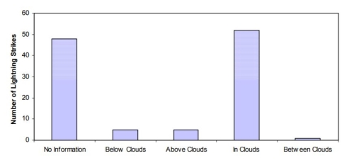
Figure 1 - Number of Lightning Strikes vs Aircraft Position
Figure 2 shows, from this Lightning strike database, the environmental conditions of the aircraft when it was struck by lightning. It can be seen from this figure that Lightning Strike mainly occurs under rain or hail conditions but in 30% of the cases there was no precipitation.

Figure 2 - Number of Lightning Strikes vs Environmental Conditions
Table 4 presents the Rates of lightning strike to Aircraft according to the IEL Group; these Rates are the results of the data from the Table 1 and Figures 1 and 2 extrapolated to VTOL Groups.
|
A/C Group |
IEL Group I VFR (1)(2) |
IEL Group I IFR (1)(2) |
IEL Group II VFR (1)(2) |
IEL Group II IFR (1)(2) |
IEL Group III VFR (1)(2) |
IEL Group III IFR(1)(2) |
|
R Lightning Strike /FH |
5.10-6 |
5.10-5 |
8.10-6 |
8.10-5 |
10-5 |
10-4 |
Table 4 - IEL Group Lightning Strike Rates
(1) For simplification it has been assumed that aircraft flying under VFR are in VMC and aircraft flying under IFR are in IMC for 50% and VMC for 50% of the flight time (so same order of magnitude between IMC and IFR)
(2) A factor 10-1 has been applied to the Rate of Lightning Strike to aircraft between IFR and VFR operations (according to data from Figures 1 and 2).
(c) Hazard on VTOL capable aircraft
By comparing the Rate of Lightning Strike and the Safety Objective at Aircraft Level, we can determine its associated Hazard category.
Table 5 provides the likelihood of the Hazard due to Lightning Strike for a given IEL Group.
|
Failure Condition A/C Group |
Catastrophic (Level A) |
Hazardous (Level B) |
Major (level C) |
|
IEL Group I VFR |
Likely (Safety Objectives 10-6) |
Unlikely (Safety Objectives 10-5) |
Unlikely (Safety Objectives 10-4) |
|
IEL Group I IFR |
Likely (Safety Objectives 10-6) |
Likely (Safety Objectives 10-5) |
Unlikely (Safety Objectives 10-4) |
|
IEL Group II VFR |
Likely (Safety Objectives 10-7) |
Likely (Safety Objectives 10-6) |
Unlikely (Safety Objectives 10-4) |
|
IEL Group II IFR
|
Very Likely (Safety Objectives 10-7) |
Likely (Safety Objectives 10-6) |
Unlikely (Safety Objectives 10-4) |
|
IEL Group III VFR |
Very Likely (Safety Objectives 10-8) |
Likely (Safety Objectives 10-6) |
Unlikely (Safety Objectives 10-4) |
|
IEL Group III IFR |
Very Likely (Safety Objectives 10-8) |
Likely (Safety Objectives 10-6) |
Likely (Safety Objectives 10-4) |
Table 5 - Likelihood of Hazard due to Lightning Strike
P Hazard = R Lightning Strike / S Safety Objective
P Hazard < 1: Hazard is Unlikely, 1 ≤ P Hazard ≤ 102: Hazard is Likely, P Hazard > 102: Hazard is Very Likely
6. Decisional Flow Chart on the Hazard related to Lightning Exposure to Aircraft
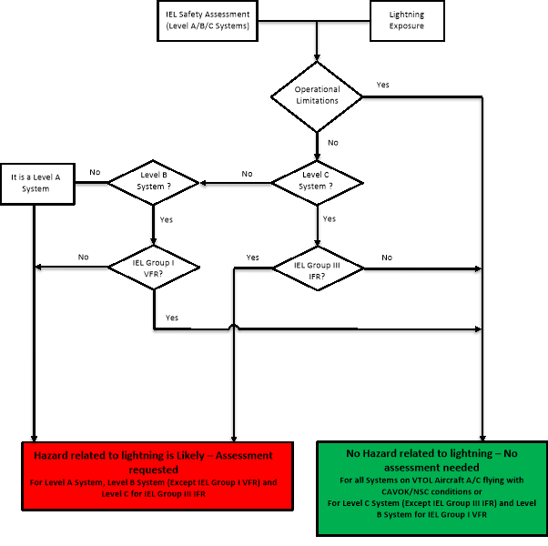
VTOL.2517 Electrical wiring interconnection system (EWIS)
n/a
(a) EWIS means any wire, wiring device, or combination of these, including termination devices, installed in any area of the aircraft for the purpose of transmitting electrical energy, including data and signals between two or more intended termination points.
(b) EWIS must be considered an integral part of the system and must be considered in showing compliance with all applicable SC VTOL requirements.
VTOL.2520 High-intensity radiated fields (HIRF) protection
n/a
(a) Each electrical and electronic system that perform a function, the failure of which would prevent continued safe flight and landing for Category Enhanced, or a controlled emergency landing for Category Basic, must be designed and installed such that:
(1) the function at the aircraft level is not adversely affected during and after the time the aircraft is exposed to the HIRF environment; and
(2) the system recovers normal operation of that function in a timely manner after the aircraft is exposed to the HIRF environment, unless the system’s recovery conflicts with other operational or functional requirements of the system.
(b) Each electrical and electronic system that performs a function, the failure of which would reduce the capability of the aircraft or the ability of the flight crew to respond to an adverse operating condition, must be designed and installed such that the system recovers normal operation of that function in a timely manner after the aircraft is exposed to the HIRF environment.
MOC VTOL.2520 High-intensity radiated fields (HIRF) protection
n/a
1. Scope of this MOC
This MOC proposes simplified methods for addressing High Intensity Radiated Fields (HIRF) compliance demonstration on VTOL capable aircraft. These methods depend on the VTOL capable Aircraft Category; Basic 0 to 1 passenger, Basic 2 to 6 passengers, Basic 7 to 9 passengers and Enhanced.
The topics covered within this MOC are: Minimum Design Requirements, HIRF Group Determination, HIRF Safety Assessment and HIRF Compliance Verification.
2. Reference Documents
The following references are quoted in different sections of this MOC as a source of additional information or to provide accepted methods and practices:
(a) Industry Standards
(1) ASTM
|
F3061/F3061M |
Specification for Systems and Equipment in Small Aircraft |
|
F3230 |
Standard Practice for Safety Assessment of Systems and Equipment in Small Aircraft |
|
F3309 |
Standard Practice for Simplified Safety Assessment of Systems and Equipment in Small Aircraft |
(2) EUROCAE/SAE/RTCA
|
ED-107A/ARP 5583A |
Guide to Certification of Aircraft in a High Intensity Radiated Field (HIRF) Environment |
|
ED-14()/DO-160() |
Environmental Conditions and Test Procedures for Airborne Equipment |
(b) Authorities Guidance
(1) FAA
|
PS-ACE-23-10 |
HIRF/Lightning Test Levels and Compliance Methods for 14 CFR Part 23 Class I, II, and III Airplanes Note: only partially recognised by EASA |
|
AC 23.1309-1E |
System Safety Analysis and Assessment for Part 23 Airplanes |
|
AC 20-158A |
The Certification of Aircraft Electrical and Electronic Systems for Operation in the High-intensity Radiated Fields (HIRF) Environment |
(2) EASA
|
Means of Compliance for VTOL Equipment Systems and installations |
|
|
AMC 20-158 |
Aircraft Electrical and Electronic System High-intensity Radiated Fields (HIRF) Protection |
3. Definitions
For the purpose of this MOC the following definitions apply:
(a) Adverse Effect: A response of a system that results in an undesirable and/or unexpected operation of an aircraft system, or undesirable and/or unexpected operation of the function performed by the system.
(b) Attenuation: Term used to denote a decrease in electromagnetic field strength in transmission from one point to another. Attenuation may be expressed as a scalar ratio of the input magnitude to the output magnitude or in decibels (dB).
(c) Equipment: Component of an electrical or electronic system with interconnecting electrical conductors.
(d) External High-intensity Radiated Fields Environment: Electromagnetic RF fields at the exterior of an aircraft.
(e) Field Strength: Magnitude of the electromagnetic energy propagating in free space expressed in volts per meter (V/m).
(f) High-intensity Radiated Fields (HIRF) Environment: Electromagnetic environment that exists from the transmission of high power RF energy into free space.
(g) High-intensity Radiated Fields (HIRF) Test level: The level of Field Strength applied during the Equipment/System Test, it may vary according the RF Band.
(h) HIRF Certification Level (HCL): The level of an electrical or electronic system that performs a function whose worst Failure Condition classification is catastrophic, hazardous or major.
(i) HIRF Group: Group of VTOL categories having the same methodology for their HIRF compliance demonstration. 3 Groups have been identified; Group I for VTOL Category “Basic 1” (0-1 passenger), Group II for VTOL Category “Basic 2” (2-6 passengers) and Group III for VTOL Categories “Basic 3” (7-9 passengers) and Enhanced.
(j) Immunity: The capacity of a system or piece of equipment to continue to perform its intended function, in an acceptable manner, in the presence of RF fields.
(k) Internal HIRF Environment: RF environment inside an airframe, equipment enclosure, or cavity. The internal RF environment is described in terms of the internal RF field strength or wire bundle current.
(l) Normal Operation: A state of the system where the system is performing its intended function. When addressing compliance with VTOL.2520 (a) (2), the function whose failure would prevent the continued safe flight and landing for Category Enhanced or a controlled emergency landing for Category Basic should be in the same undisturbed state than before exposure to the HIRF threat. Other functions, performed by the same system, subject to VTOL.2520 (b), are not required to be recovered.
(m) Radio Frequency (RF): Frequency useful for radio transmission. The present practical limits of RF transmissions are roughly 10 kilohertz (kHz) to 100 gigahertz (GHz). Within this frequency range, electromagnetic energy may be detected and amplified as an electric current at the wave frequency.
(n) System: The piece of equipment connected via electrical conductors to another piece of equipment, both of which are required to make a system function. A system may contain pieces of equipment, components, parts, and wire bundles.
(o) Transfer Function: The ratio of the electrical output of a system to the electrical input of a system, expressed in the frequency domain. For HIRF, a typical transfer function is the ratio of the current on a wire bundle to the external HIRF field strength, as a function of frequency.
(p) Upset: An impairment of system operation, either permanent or momentary. For example, a change of digital or analogue state that may or may not require a manual reset.
4. Means of Compliance
(a) Minimum Design Considerations
(1) In order to utilise the methods described in this practice, the following minimum design considerations should be addressed. If deviations from these minimum design considerations are desired, the acceptability of the methods described should be agreed to by the Agency.
(2) The airframe should incorporate low impedance electrical conductors to allow induced current to flow through the aircraft. The low impedance conductors should be incorporated into the basic structure of the aircraft.
(i) For aircraft with primarily metal structure, the metal skin provides a low impedance electrical conductor. Standard rivets and bolts should provide adequate electrical bonding between permanent structural joints. Electrical bonding straps or jumpers should be installed on moving parts or for removable panels or parts.
(ii) For aircraft with primarily carbon fibre or fiberglass structure, metal mesh, metal foil, or expanded metal foil should be incorporated onto the external surfaces of the aircraft composite structure. This mesh or foil should be joined together electrically and provide a continuous electrical conductor between the extremities of the aircraft. Metallic components that are internal to the structure of the aircraft may also be used to provide similar shielding for equipment and its wiring.
(iii) For aircraft constructed of tube and fabric, the tube skeleton can be considered to be the low impedance electrical path through the aircraft. The bonding also may be achieved by the use of bonding straps or jumpers where required to electrically bond other metallic sub-structure that might be relied upon to provide bonding for equipment.
(3) Electrical bonding specifications and verifications should be developed and implemented on the production drawings and instructions for continued airworthiness.
(b) HIRF Group Determination
The HIRF Group should be identified by using Table 1; the relevant Group will determine the HIRF Compliance Verification method given in paragraph (d).
|
|
VTOL Categories |
|||
|
Basic (max passenger seating configuration) |
Enhanced |
|||
|
0-1 |
2-6 |
7-9 |
||
|
HIRF Group |
I |
II |
III |
III |
|
|
|
|
|
|
Table 1 – HIRF Group Allocation
(c) HIRF Safety Assessment
(1) The VTOL capable aircraft systems that require a HIRF Safety Assessment should be identified. The elements of the system that perform a function should be defined, considering the use of redundant and/or backup equipment that constitutes the system. The process used for identifying these systems should be similar to the process used for showing compliance with VTOL.2510. This requirement addresses any system failure that may cause or contribute to an effect on the safety of flight of a VTOL capable aircraft. The effects of a HIRF encounter should be assessed to determine the degree to which the aircraft and its systems safety may be affected. The operation of the aircraft systems should be assessed separately and in combination with, or in relation to, other systems. This assessment should cover:
(i) All normal VTOL capable aircraft operating modes, stages of flight, and operating conditions;
(ii) All failure conditions and their subsequent effect on VTOL capable aircraft operations and the flight crew; and
(iii) Any corrective actions required by the flight crew
(2) A safety assessment related to HIRF should be performed to establish and classify the equipment or system failure condition. Table 2 provides the corresponding Failure condition classification and system HIRF certification level for VTOL.2520. The HIRF safety assessment determines the consequences of failures, due to HIRF, for the aircraft functions that are performed by the system. The HIRF Certification Level (HCL) classification assigned to the system and functions can be different from the Design Assurance Levels assigned for equipment function and/or item (software, and complex electronic hardware). This is because HIRF is an environment that can cause common cause effects. The term ‘Design Assurance Level’ should not be used to describe the HIRF Certification Level because of the potential differences in assigned classifications for software, complex electronic hardware, and equipment function
|
HIRF Requirements VTOL.2520 |
MOST CRITICAL FAILURE CONDITION OF THE FUNCTION |
SYSTEM HIRF CERTIFICATION LEVEL (HCL) |
|
(a) Each electrical and electronic system that performs a function, the failure of which would prevent continued safe flight and landing for Category Enhanced, or a controlled emergency landing for Category Basic, must be designed and installed such that: (1) The function at the aircraft level is not adversely affected during and after the time the aircraft is exposed to the HIRF environment; and (2) The system recovers normal operation of that function in a timely manner after the aircraft is exposed to the HIRF environment, unless the system’s recovery conflicts with other operational or functional requirements of the system. |
Catastrophic |
A |
|
(b) Each electrical and electronic system that performs a function, the failure of which would reduce the capability of the aircraft or the ability of the flight crew to respond to an adverse operating condition, must be designed and installed such that the system recovers normal operation of that function in a timely manner after the aircraft is exposed to the HIRF environment. |
Hazardous/Major |
B/C |
Table 2 – HIRF Failure Conditions and System HIRF Certification Level
(3) The HIRF safety assessment should consider all potential adverse effects due to system failures; loss, malfunctions or misleading information caused by a HIRF threat. The HIRF safety assessment may show some systems have different failure conditions in different phases of flight; therefore, the HCL corresponds to the most critical Failure Condition.
(4) In addressing the Failure Condition in Table 2, the nature of HIRF should be considered. The potential for common causes of failures across multiple equipment/systems performing the same or different functions due to the simultaneous exposure to the HIRF threat should be considered. Mechanical systems can be considered inherently immune to HIRF and may be used in the safety assessment.
(5) In addressing the Failure Condition in Table 2, the effects of HIRF should not be combined with random failures that are not the result of the HIRF threat.
(6) Due to the similar approach in the safety assessment process related to IEL and HIRF, the System Certification Levels for HIRF and Lightning are usually the same.
(d) HIRF Compliance Verification
(1) By applying the ‘Net Safety Benefit’ approach6For additional information, refer to the EASA Proposed Certification Memorandum CM-SA-001 published in the EASA Website: Proposed Certification Memorandum CM-SA-001 - Net Safety Benefit - Issue 01 | EASA (europa.eu) on the lower HIRF Group, VTOL.2520 (b) is not applicable for level C system of HIRF Groups I and II, it could be removed from the Compliance Verification.
(i) For Level A Non-Display Systems:
(A) Follow AMC 20-158; or
(B) Conduct Equipment/System testing using the following default levels:
(a) Conducted susceptibility testing with the Generic transfer function for aircraft (according to VTOL shape and size) extrapolated to the HIRF Environment III (as defined in Section 5) corresponding to the EUROCAE ED-14G section 20 categories Y or W.
(b) Radiated Susceptibility testing with Generic attenuation curves (depending on equipment location) extrapolated to the HIRF Environment III (as defined in Section 5) corresponding to the EUROCAE ED-14G section 20 categories L, G or F
(c) Fail/Pass Criteria; when subjected to the HIRF Environment, it could be acceptable that redundant equipment is/are subject to adverse effects, provided that the Level A function is maintained at the aircraft level and all the Equipment/Systems that are required in normal operation recover manually or automatically, in a timely manner, this function after the threat.
(ii) For Level A Display Systems:
(A) Follow the AMC 20-158; or
(B) Conduct Equipment/System testing using the following default levels:
(c) Fail/Pass Criteria; when subjected to the HIRF Environment, it could be acceptable that redundant equipment is/are subject to adverse effects, provided that the Level A function is maintained at the aircraft level and all the Equipment/Systems that are required in normal operation recover manually or automatically, in a timely manner, this function after the threat.
(A) Follow the AMC 20-158 (by using Equipment HIRF Test Levels 1 or 2 as defined in Section 5); or
(B) Conduct Equipment/System testing as defined in (d) (2) (ii) (B) (a) and (b); when submitted to the HIRF Environment, if the Equipment/System subject to adverse effects does not to recover its level B function after the threat, the method proposed by the AMC 20-158 for Level B systems in (d) (2) (iii) (A) can be used as an alternatively.
(i) For Level A Non-Display Systems:
(A) Follow the AMC 20-158; or
(B) Conduct Equipment/System testing using the following default levels:
(a) Conducted susceptibility testing with the real transfer function of the aircraft (determined by Low Level coupling test, analysis, combination of both or similarity) extrapolated to the HIRF Environment III (as defined in Section 5).
(b) Radiated Susceptibility testing with real attenuation curves (determined by Low level Testing, analysis, combination of both or similarity) extrapolated to the HIRF Environment III (as defined in Section 5).
(c) Fail/Pass Criteria; when submitted subjected to the HIRF Environment, it could be acceptable that redundant equipment is/are subject to adverse effects, provided that the Level A function is maintained at the aircraft level and all the Equipment/Systems that are required in normal operation recover manually or automatically, in a timely manner, this function after the threat.
(ii) For Level A Display Systems:
(A) Follow the AMC 20-158; or
(B) Conduct Equipment/System testing using the following default levels:
(c) Fail/Pass Criteria; when subjected to the HIRF Environment, it could be acceptable that redundant equipment are subject to adverse effect, provided the Level A function is maintained at the aircraft level and all the Equipment/Systems required in normal operation recover manually or automatically, in a timely manner, this function after the threat.
(iii) For Level B Systems:
(A) Follow the AMC 20-158 (by using Equipment HIRF Test Levels 1 or 2 as defined in Section 5); or
(B) Conduct Equipment/System testing as defined in(d) (3) (ii) (a) and (b); when submitted to the HIRF Environment, if the Equipment/System, subject to adverse effects, does not to recover to its level B function after the threat, the method proposed by the AMC 20-158 for Level B systems in (d) (3) (iii) (A) can be used as an alternative.
(A) Follow the AMC 20-158 (by using Equipment HIRF Test Level 3 as defined in Section (5); or
(B) Conduct Equipment/System testing as defined in (d) (3) (ii) (a) and (b); when submitted to the HIRF Environment, if the Equipment/System, subject to adverse effects, does not to recover to its level C function after the threat, the method proposed by the AMC 20-158 for Level C systems in (d) (3) (iv)(A) can be used as an alternative.
(4) HIRF Testing for Level A systems considerations;
(i) The Test Levels for upper HIRF Group can also be used for lower HIRF Groups; for instance the use of real transfer function and attenuation curves and/or more severe External HIRF Environment can be used for Level A Systems of HIRF Groups I/II.
(ii) Equipment testing is acceptable when it is shown that the interdependencies between equipment performing a function are understood and each equipment is tested and monitored to verify that there are no unacceptable upsets of the function.
(iii) If similar equipment are used to perform the same function; the test can be limited to a single equipment.
(5) Level A System architecture consideration; when a Level A system comprises redundant channels/equipment that perform the same level A function, it is permitted to limit the system to the channels/equipment that are required in normal operation provided that they are not susceptible when they comply with VTOL.2520(a); for instance if it is demonstrated that the primary channels comply with VTOL.2520(a) without the support of the back-up channel, this channel is not requested to be exposed to the HIRF Environment I/III, however this back-up channel should be considered to be a level B system.
5. HIRF Environments and Equipment HIRF Test Levels
This Section specifies the HIRF environments and equipment HIRF test levels for electrical and electronic systems under VTOL.2520.
(a) HIRF environment I is specified in the following Table 3:
|
FREQUENCY |
FIELD STRENGTH (V/m) |
|
|
PEAK |
AVERAGE |
|
|
10 kHz - 2 MHz |
50 |
50 |
|
2 MHz - 30 MHz |
100 |
100 |
|
30 MHz - 100 MHz |
50 |
50 |
|
100 MHz – 400 MHz |
100 |
100 |
|
400 MHz – 700 MHz |
700 |
50 |
|
700 MHz - 1 GHz |
700 |
100 |
|
1 GHz - 2 GHz |
2000 |
200 |
|
2 GHz - 6 GHz |
3000 |
200 |
|
6 GHz - 8 GHz |
1000 |
200 |
|
8 GHz - 12 GHz |
3000 |
300 |
|
12 GHz - 18 GHz |
2000 |
200 |
|
18 GHz - 40 GHz |
600 |
200 |
In this table, the higher field strength applies at the frequency band edges.
(b) HIRF environment II is specified in the following Table 4:
|
FREQUENCY |
FIELD STRENGTH (V/m) |
|
|
PEAK |
AVERAGE |
|
|
10 kHz – 500 kHz |
20 |
20 |
|
500 kHz - 2 MHz |
30 |
30 |
|
2 MHz - 30 MHz |
100 |
100 |
|
30 MHz – 100 MHz |
10 |
10 |
|
100 MHz – 200 MHz |
30 |
10 |
|
200 MHz - 400 MHz |
10 |
10 |
|
400 MHz - 1 GHz |
700 |
40 |
|
1 GHz - 2 GHz |
1300 |
160 |
|
2 GHz - 4 GHz |
3000 |
120 |
|
4 GHz - 6 GHz |
3000 |
160 |
|
6 GHz - 8 GHz |
400 |
170 |
|
8 GHz - 12 GHz |
1230 |
230 |
|
12 GHz – 18 GHz |
730 |
190 |
|
18 GHz - 40 GHz |
600 |
150 |
In this table, the higher field strength applies at the frequency band edges.
(c) HIRF environment III is specified in the following Table 5:
Table 5 — HIRF Environment III
|
FREQUENCY |
FIELD STRENGTH (V/m) |
|
|
PEAK |
AVERAGE |
|
|
10 kHz – 100 kHz |
150 |
150 |
|
100 kHz - 400 MHz |
200 |
200 |
|
400 MHz - 700 MHz |
730 |
200 |
|
700 MHz – 1 GHz |
1400 |
240 |
|
1 GHz - 2 GHz |
5000 |
250 |
|
2 GHz - 4 GHz |
6000 |
490 |
|
4 GHz - 6 GHz |
7200 |
400 |
|
6 GHz - 8 GHz |
1100 |
170 |
|
8 GHz - 12 GHz |
5000 |
330 |
|
12 GHz – 18 GHz |
2000 |
330 |
|
18 GHz - 40 GHz |
1000 |
420 |
In this table, the higher field strength applies at the frequency band edges.
(d) Equipment HIRF Test Level 1.
Equipment Level Test ED-14G (or later Revision) Cat R for both conducted and radiated susceptibility.
(e) Equipment HIRF Test Level 2.
Equipment HIRF test level 2 is HIRF environment II in table 4 of this Section reduced by acceptable generic aircraft transfer function and attenuation curves. Testing should cover the frequency band of 10 kHz to 8 GHz.
(f) Equipment HIRF Test Level 3.
Equipment Level Test ED-14G (or later Revision) Cat T for both conducted and radiated susceptibility.
VTOL.2525 System power generation, energy storage, and distribution
n/a
The power generation, energy storage, and distribution for any system, as applicable, must be designed and installed to:
(a) supply the power required for operation of connected loads during all intended operating conditions;
(b) reserved;
(c) reserved.
VTOL.2530 External and cockpit lighting
n/a
(a) All lights must be designed and installed to minimise any adverse effects on the performance of flight crew duties.
(b) Any position and anti-collision lights, if required by operational rules, must have the intensities, flash rate, colours, fields of coverage, and other characteristics to provide sufficient time for another aircraft to avoid a collision.
(c) Any position lights, if required by operational rules, must include a red light on the left side of the aircraft, a green light on the right side of the aircraft, spaced laterally as far apart as practicable, and a white light facing aft, located on an aft portion of the aircraft fuselage or on the wing tips.
(d) Taxi and landing lights, if required, must be designed and installed so they provide sufficient light for night operations.
(e) If certification for intended operations on water is requested, riding lights must provide a white light visible in clear atmospheric conditions.
MOC VTOL.2530 External and Cockpit Lighting
n/a
1. Instrument lights
CS 23.1381 Amdt. 4 is accepted as means of compliance with VTOL.2530 (a) for the instrument lights.
Depending on the aircraft configuration, either CS 23.1381 Amdt. 4 or CS 27.1383 Amdt. 6 is accepted as means of compliance with VTOL.2530 (a) and VTOL.2530 (d) for taxi and landing lights. The applicability of CS 23.1381 or CS 27.1383 as means of compliance should be agreed with the Agency based on the configuration of the aircraft in order to ensure that the objective of VTOL.2530 is fully met.
3. Position light
Depending on the aircraft configuration, either paragraphs from CS 23.1385 to CS 23.1397 Amdt. 4, both inclusive, or paragraphs from CS 27.1385 to CS 27.1397 Amdt. 6, both inclusive, are accepted as means of compliance with VTOL.2530 (a), (b) and (c) for the position lights. The applicability the aforementioned CS-23 or CS-27 requirements as means of compliance should be agreed with the Agency based on the configuration of the aircraft in order to ensure that the objective of VTOL.2530 is fully met.
4. Riding lights
CS 27.1399 Amdt. 6 is accepted as means of compliance with VTOL.2530 (a) and VTOL.2530 (e) for riding lights.
5. Anti-collision lights
(a) The anti-collision lights are intended to attract attention to the aircraft and they should be designed and installed to ensure minimum performances in terms of intensities, flash rate, colours and fields of coverage, in order to be capable to provide sufficient visibility in a timely manner for another aircraft to avoid a collision. CS 23.1401 Amdt. 4 is accepted as means of compliance with VTOL.2530 (b) and meets this intent.
(b) In order to show compliance with VTOL.2530 (a), any potential adverse effects of the lights operations on the satisfactory performance of the flight crew duties should be assessed, for instance cockpit reflections or any possible effects of rotor or propeller blade strobing.
(c) Other means than (a) may be proposed and agreed with the Agency to comply with VTOL.2530(a) and (b). They may be based either on the outcome of the assessment in (b) or on a different rationale. For instance, they could also have the purpose to comply with operational or local regulations in the intended operational environment by preventing harmful dazzle to outside observers, reducing light pollution, etc. The following examples provide methods that can be acceptable upon agreement with the Agency:
(1) Installation of red anti-collision lights compliant with CS 27.1401 Amdt. 6. The applicant has to justify that the performances of the lights (intensities, flash rate, colour and fields of coverage) are sufficient to satisfy the intent of VTOL.2530 (b) for the specific VTOL capable aircraft design and operations;
(2) Installation of anti-collision lights compliant with CS 23.1401 Amdt 4 with additional provisions aimed to adapt and make compatible the intensity of the lights with certain operational conditions or environments, e.g. by providing means for the flight crew to reduce the intensity of the lights and switch them off;
(3) Installation of an anti-collision lighting system comprising a combination of lights compliant with (1) and lights compliant with (2).
n/a
Safety and survival equipment, required by the operating rules, must be reliable, readily accessible, easily identifiable, and clearly marked to identify its method of operation.
MOC VTOL.2535 Safety Equipment
n/a
[MOC 2 - Issue 3]
CS27.1411 Amdt. 5 (or later) is accepted as a means of compliance.
For overwater operations, the combination of CS27.1415 Amdt. 5 (or later) and CS29.1415(d) Amdt. 5 (or later) is accepted as a means of compliance for the installation of additional safety equipment as required by any applicable operating rule.
Each emergency locator transmitter, including sensors and antennae, required by the applicable operating rule, should be installed so as to minimise damage that would prevent its functioning following an accident or incident. (See AMC 27.1470 Amdt. 5 (or later))
VTOL.2545 Pressurised systems elements
n/a
Pressurised systems must withstand appropriate proof and burst pressures.
VTOL.2555 Installation of flight recorders
n/a
The aircraft must be equipped with an approved flight recorder or recorders that:
(a) is installed so as to ensure accurate recording for at least 5 hours and appropriate safeguarding of the data supportive for accident investigation;
(b) is powered by the most reliable power source and remains powered for as long as possible without jeopardising service to essential or emergency loads and emergency operation of the aircraft;
(c) has a high proportion of its outer surface area coloured in bright orange; and dimensions that are adequate for visually locating it on an accident scene;
(d) is installed so that it automatically records prior to the aircraft being capable of moving under its own power and stops automatically following lift/thrust units powering off; and
(e) except for some data approved by EASA to be transmitted and recorded remotely, records in an accepted digital data, audio or image format, and with reference to a timescale:
(1) information that is sufficient to determine the flight path and speed;
(2) communications with air traffic services;
(3) audio from the flight crew compartment for installations intending to support multicrew and VEMS operations;
(4) information provided to the crew and necessary for the safe operation of the aircraft.
(f) If the installation has an erasure device or function, the installation must be designed to minimise the probability of inadvertent operation and actuation of the erasure device or function during crash impact.
MOC VTOL.2555 Installation of recorders
n/a
This MOC is applicable to each recorder installed to comply with VTOL.2555.
(a) General:
The recorder should have an ETSO authorisation against one of the following ETSOs or a later equivalent:
(1) ETSO-C123b; or
(2) ETSO-C124b; or
(3) ETSO-2C197
(b) Recorder installation:
The container of the recording medium should be located and mounted so as to minimise the probability of the container rupturing or the recording medium being destroyed as a result of impact with the Earth’s surface or of heat damage caused by a post-impact fire.
The structural provisions within the aircraft for the mounting of the recorder should be able to withstand the loads resulting from severe vibration (such as those resulting from rotor imbalance). In addition, the strength of the local attachments should be able to withstand the crash safety loads in CS 27.561(b)(3).
If the recorder has an erasure device or function, the installation must be designed to minimise the probability of inadvertent operation and actuation of the erasure device or function during crash impact.
(c) Recorder identification:
A high proportion of the area of the outer surfaces of the container of the memory medium should be coloured bright orange.
The height, width and depth of the container of the memory medium must each be 4 cm (1.5 inches) or greater
(d) Recorder characteristics:
The recorder should:
(1) Permit quick downloading of the flight parameters without having to remove the recorder;
(2) Be capable of retaining the flight parameters that are recorded during at least the preceding 5 hours and the audio recording during at least the preceding 2 hours;
(3) Automatically start to record as early as possible after power-on and in any case prior to the aircraft being capable of moving under its own power;
(4) Continue to record until the termination of the flight when the aircraft is no longer capable of moving under its own power;
(5) If the recorder has a recording duration of less than 25 hours, have a means for the flight crew to stop the recording upon completion of the flight in such a way that re-enabling the recording is only possible by a dedicated manual action.
(e) Flight Parameters and audio recording:
The recorder, or the combination of recorders installed to comply with VTOL.2555, should:
(1) Record the flight parameters required to accurately determine the flight path, speed, attitude, engine power, operation and configuration of the VTOL capable aircraft. The minimum list of flight parameters to be recorded is provided in paragraphs (j) and (l). All recorded parameter values should be accurately time-stamped according to a common time reference and be recorded at a rate not below 4 Hz;
(2) For aircraft with a minimum flight crew of two pilots, simultaneously record, on separate channels and with reference to a timescale:
(i) The aural environment of the cockpit (area microphone;)
(ii) Pilots’ headset audio, including but not limited to voice communications, audio signals for navigation aids, aural alerts.
(f) Maintenance instructions:
(1) When developing the ICA for the recorder systems, the applicant should address all the failures that may affect their correct functioning or the quality of the recorded information.
Note: ‘Recorder systems’ designates the recorders and their dedicated equipment (e.g. dedicated sensors or transducers, dedicated data busses, dedicated power source…).
(2) Examples of failures (indicative and non-exhaustive list):
(i) Loss of the recording function or of the acquisition function of the recorder;
(ii) Failure of a means to facilitate the finding of the recording medium after an accident (e.g. an underwater locating device or an emergency locator transmitter attached to the recorder);
(iii) Failure of a means to detect a crash impact (for the purpose of stopping the recording after a crash impact, or for the purpose of deploying the recorder if it is deployable);
(iv) Failure of any power source dedicated to the recorder (e.g. dedicated battery);
(v) Failure of the start-and-stop function;
(vi) Failure of a sensor dedicated to the recorder system;
(vii) For flight parameters recording, when any required parameter is missing, or is not correctly recorded;
(viii) For audio recording (if applicable):
(ix) Any required audio signal is missing, or is recorded with an audio quality that is rated ‘poor’ (refer to the example of audio quality rating provided in Section 9 of AMC 25.1459);
(x) Failure of a transducer or amplifier dedicated to the recorder system (e.g. failure of the cockpit area microphone).
(g) Data transmission & ground recording: [Reserved]
(1) Time
(2) Altitude
(3) Latitude
(4) Longitude
(5) Indicated airspeed or calibrated airspeed
(6) Groundspeed
(7) Outside Air Temperature (OAT)
(8) Heading (magnetic or true)
(9) Track
(10) Vertical speed
(11) Pitch attitude
(12) Roll attitude
(13) Longitudinal acceleration (body axis)
(14) Normal acceleration
(15) Lateral acceleration
(16) Roll rate or Roll acceleration
(17) Pitch rate or Pitch acceleration
(18) Yaw rate or yaw acceleration
(19) If electric engines are used:
(i) Electric Engines: rotation speed of each rotor (in RPM)
(ii) Electric Engines: health status of each electric engine controller
(iii) Electric Engines: temperature of each electric engine
(iv) Electric Engines: temperature of each electric engine controller
(v) Electric Engines: measured electrical current for each electric engine
(vi) For liquid cooled electric engines: pressure and temperature of the cooling liquid
(20) Flight controls
(i) Pilot input positions on all axis and corresponding flight control,
(ii) Outputs (e.g. target RPM for each electric engine, flight surface positions, …)
(21) Status of each flight control computer
(22) Wings angle (if applicable)
(23) Nacelles angles (if applicable)
(24) Propeller pitch (for each variable pitch propeller)
(25) Air-Ground status such as Weight on Wheels or equivalent parameter
(26) Alerts (including master warning and master caution status)
(27) Manual voice transmission keying (if voice communications are used)
(28) For each battery used for propulsion and/or flight controls:
(i) Health status, State Of Charge (SOC), voltage, temperature, current flow,
(ii) if available:
(A) State of Power (SOP); or
(B) Calculated remaining flight time.
(29) Health status of each electrical distribution unit (e.g. distribution units, converters) contributing to the propulsion and/or flight controls
(30) Status of the battery management system (if any)
(31) If combustion engine(s) are used:
(i) Fuel parameters;
(ii) Oil pressure and oil temperature;
(iii) Parameters required to determine propulsive thrust or power delivered;
(iv) Turbine RPM (if applicable);
(v) FADEC health status (if applicable);
(vi) Aircraft inputs used by the FADEC (if applicable);
(vii) Any electrical current generation; and
(viii) Any other parameter subject to a limitation
(i) In addition, the following flight parameters should be recorded if they are used by the aircraft systems or are available for use by the pilot to operate the aircraft. They should be recorded with a recording resolution at least as high as specified in EUROCAE Documents ED-155 or ED-112:
(1) Active AFCS mode
(2) Radio altitude or terrain elevation
(3) Current navigation source,
(4) Vertical and lateral deviation with respect to current active navigation path
(5) DME 1 & 2 distances
(6) Drift angle
(7) Wind speed
(8) Wind direction
(9) Landing gear position
(10) Ice: ice detection, status of de-icing or anti-icing system
(11) Electric Engine: vibration level
(12) Traffic advisories or alerts, if installed (e.g. ADS-B IN, ACAS…)
(13) Obstacle and terrain alerts, if installed (e.g. TAWS, …)
(1) data link communication messages to and from the aircraft, including messages applying to the following applications:
(i) data link initiation and termination,
(ii) controller-pilot communication,
(iii) addressed surveillance,
(iv) flight information, including weather data (if required for operation),
(v) aircraft broadcast surveillance,
(vi) aircraft operational control data, and
(vii) graphics.
(2) information that enables correlation to any associated records related to data link communications and stored separately from the helicopter; and
(3) information on the time and priority of data link communications messages, taking into account the system’s architecture.