
n/a
The structure must support
(a) limit loads without:
(1) interference with the safe operation of the aircraft; and
(2) detrimental or permanent deformation.
(b) ultimate loads.
MOC VTOL.2235 Structural strength
n/a
|
Note: At this issue, this MOC addresses landing gear drop test requirements only. Additional MOC will be added in future issues to address, for example, allowable damages to the aircraft for the Category Basic controlled emergency landing. |
(a) Shock absorption tests: CS 27.723 Amdt. 6 is accepted as a means of compliance.
(b) Limit drop test: CS 27.725 Amdt. 6 is accepted as a means of compliance.
(c) Reserve energy absorption drop test: CS 27.727 Amdt. 6 is accepted as a means of compliance. In addition:
(1) Shock absorbing devices, such as oleos, should not “bottom” during the reserve energy drop test. “Bottoming” occurs when displacement of the device no longer occurs with increasing load. (for further guidance see FAA AC 27.727(a)(3) in FAA AC 27-1B Change 7, which is the EASA AMC as per Book 2 of CS-27 Amdt. 6)
Notes:
(1) The proper attitude for the aircraft after the reserve energy absorption drop test is an attitude which allows for permanent deformation of landing gear elements but provides for adequate egress from the aircraft (for further guidance see FAA AC 27.727A (b)(1) in FAA AC 27-1B Change 7, which is the EASA AMC as per Book 2 of CS-27 Amdt. 6).
(2) External accessories that may not impact the landing surface during drop testing include devices such as externally mounted fuel tanks or accessories that are likely to cause post-landing fires. Cameras, loudspeakers, and search lights may be damaged during deformations resulting from reserve energy drop tests if electrical connections are sufficiently protected to preclude electrical fires and the devices are not likely to penetrate fuel tanks and other energy sources. The expendable accessories, if installed, should also be designed to not have “hard points” that would unacceptably damage the aircraft structure under landing impacts by penetration into the occupied areas or fuel tanks. These expendable accessories should be designed with frangible fittings, frangible devices, or comparable design features. Also, these devices should be designed to not significantly alter the energy absorbing ability or design features of the landing gear (for further guidance see FAA AC 27.727A (b)(2) in FAA AC 27-1B Change 7, which is the EASA AMC as per Book 2 of CS-27 Amdt. 6).
(3) External accessories may not contact a level landing surface after “limit landing load” deflection of the landing gear, i.e. the deflection resulting from the limit drop test described in paragraph A of this MOC.
VTOL.2240 Structural Durability
n/a
(a) The applicant must develop and implement inspections or other procedures to prevent structural failures due to foreseeable causes of strength degradation, which could result in serious or fatal injuries, or extended periods of operation with reduced safety margins. Each of the inspections or other procedures developed under VTOL.2240 must be included in the Airworthiness Limitations Section of Instructions for Continued Airworthiness required by VTOL.2625.
(b) For Category Enhanced, the procedures developed for compliance with VTOL.2240(a) must be capable of detecting structural damage before the damage could result in structural failure.
(c) Reserved.
(d) The aircraft must be designed to minimise hazards due to structural damage caused by high-energy fragments from an uncontained lift/thrust unit or rotating-machinery failure.
(e) For Category Enhanced, provisions for in-service monitoring of parts having an important bearing on safety in operations must be established.
MOC VTOL.2240 (a) and (b) Structural durability
n/a
1. Introduction
VTOL.2240 (a) and (b) requests the applicant to perform all necessary evaluations and actions (inspection, procedures) “to prevent structural failures due to strength degradation, which could result in serious or fatal injuries, or extended periods of operation with reduced safety margins.”
For the category Basic, this comprises of any relevant inspections or other procedures to prevent structural failure (e.g. replacement time for safe life evaluation).
For the category Enhanced, this includes any relevant inspections or other procedures to detect structural damages before failure (Damage Tolerance evaluation).
A distinction is thus made between categories Basic and Enhanced concerning durability: while both categories have the same objective to prevent structural failures due to strength degradation, for Enhanced category the detection of structural damage is added to VTOL.2240(a).
Table 1 summarises the accepted means to demonstrate compliance with VTOL.2240 (a) and (b) regarding structural durability and the associated guidance material additionally applicable:
Table 1: Summary of the means of compliance for categories basic and enhanced
|
Type of Structure |
Category Basic |
Category Enhanced |
|
Metallic |
Sections 7 and 8 in this MOC, which include the adaptation of CS 27.571 (Amdt. 6) “Fatigue evaluation of flight structure” and of AC 27.571
Instead, it is also accepted to use Sections 3 and 4 in this MOC which include an adaptation of CS 29.571 “Fatigue evaluation of metallic structure” (Amdt. 6) and of AC 29.571 |
Sections 3 and 4 in this MOC, which include the adaptation of CS 29.571 (Amdt. 6) “Fatigue evaluation of metallic structure” and of AC 29.571 (flaw tolerance and crack growth method) |
|
Composite |
Sections 5 and 6 in this MOC, which include the adaptation of CS 27.573 (Amdt. 6) “Fatigue evaluation of composite rotorcraft structures” and of AC 27.573 and AMC 20-29. |
|
|
Design precaution for metallic and composite |
CS 23.627 (Amdt 4) “Fatigue strength” is accepted as means of compliance |
|
2. Selected Structural Elements (SSE)
Selected Structural Elements (SSE) are parts which carry flight or ground loads, or parts loaded in fatigue the failure of which would reduce the structural integrity of the aircraft.
The following is a non-exhaustive list of SSE examples:
(a) Wing and empennage.
(1) Control surfaces, slats, flaps, and their mechanical systems and attachments (hinges, tracks, and fittings);
(2) Integrally stiffened plates;
(3) Primary fittings;
(4) Principal splices;
(5) Skin or reinforcement around cutouts or discontinuities;
(6) Skin-stringer combinations;
(7) Spar caps; and
(8) Spar webs.
(b) Fuselage.
(1) Frames and adjacent skin;
(2) Door frames;
(3) Pilot-window posts;
(4) Structural bulkheads;
(5) Skin and any single frame or stiffener element around a cutout;
(6) Skin or skin splices, or both,
(7) Door skins, frames, and latches; and
(8) Window frames.
(c) Landing gear and their attachments.
(d) Engine mount/supports
(e) Lift Thrust Units
(1) Rotors including blades, propeller, hubs
(2) Rotor drive systems between the engines and the rotor hubs,
(3) Transmission mounting
(f) Fixed and rotating control system
3. Means of Compliance for structural durability of metallic structures in the category Enhanced:
(a) Each Selected Structural Element (SSE) should be identified, as defined in Section 2 of this MOC.
(b) A fatigue tolerance evaluation of each SSE should be performed, and appropriate inspections and retirement time or approved equivalent means should be established to avoid failure during the operational life of the VTOL.
(c) Each fatigue tolerance evaluation should include:
(1) In-flight measurements to determine the fatigue loads or stresses for the SSEs identified in (b) in all critical conditions throughout the range of design limitations required in MOC VTOL.2200 (including altitude effects), except that manoeuvring load factors need not exceed the maximum values expected in operations.
(2) The loading spectra as severe as those expected in operations based on loads or stresses determined under (c)(1), including external load operations, if applicable, and other high frequency power-cycle operations.
(3) Take-off, landing, and taxi loads when evaluating the landing gear (including skis and floats) and other affected SSEs.
(4) For each SSE identified in (b), a threat assessment, which includes a determination of the probable locations, types, and sizes of damage taking into account fatigue, environmental effects, intrinsic and discrete flaws, or accidental damage that may occur during manufacture or operation.
(5) A determination of the fatigue tolerance characteristics for the SSE with the damage identified in (c)(4) that supports the inspection and retirement times, or other approved equivalent means.
(6) Analyses supported by test evidence and, if available, service experience.
(d) A residual strength determination should be performed that substantiates the maximum damage size assumed in the fatigue tolerance evaluation. In determining inspection intervals based on damage growth, the residual strength evaluation should show that the remaining structure, after damage growth, is able to withstand design limit loads without failure.
(e) The effect of damage on stiffness, dynamic behaviour, loads and functional performance should be considered.
(f) The inspection and retirement times or approved equivalent means established under this Section should be included in the Airworthiness Limitation Section of the Instructions for Continued Airworthiness required by VTOL.2625
(g) If inspections for any of the damage types identified in (c)(4) cannot be established within the limitations of geometry, inspectability, or good design practice, then supplemental procedures, in conjunction with the SSE retirement time, should be established to minimize the risk of occurrence of these types of damage that could result in a failure during the operational life of the VTOL capable aircraft.
(h) Discrete source damage tolerance evaluation. The aircraft should be capable of successfully completing a flight during which likely structural damage occurs as a result of
(1) Uncontained High-Energy Fragments and Sustained Imbalance as specified in VTOL.2240 (d)
(2) Bird impact as specified in VTOL.2250
4. Additional guidance for structural durability of metallic structures in the category Enhanced:
Table 2 below provides the necessary adaptations to use AC 29.571 A and B as additional guidance for the fatigue of metallic structures in the category Enhanced:
Table 2: Adaptations to AC 29.571 A and B for the fatigue of metallic structures in the category Enhanced
|
AC 29.571A. § 29.571 (Amendment 29-28) FATIGUE TOLERANCE EVALUATION OF STRUCTURE AC 29.571B. § 29.571 (Amendment 29-55) FATIGUE TOLERANCE EVALUATION OF METALLIC STRUCTURE |
||
|
General Changes/Adaptations
|
||
|
To be replaced by “VTOL capable aircraft” |
||
|
“the FAA” and “the Administrator” |
To be replaced by “EASA” |
|
|
“Principal Structural Element” or “PSE” |
To be replaced by “Selected Structural element” or “SSE” |
|
|
“§ 29.571” |
To be replaced by “VTOL.2240 (a) and (b)” |
|
|
“Catastrophic failure” |
Concept not applicable to the VTOL durability objective. To be replaced by “failure”. |
|
|
“§ 29.309” |
To be replaced by “VTOL.2200” |
|
|
“§ 29.1529” |
To be replaced by “VTOL.2625 Instructions for Continued Airworthiness” |
|
|
AC 29.571A. § 29.571 (Amendment 29-28) FATIGUE TOLERANCE EVALUATION OF STRUCTURE |
||
|
Paragraph |
Changes/ Adaptations in addition to the “General changes/adaptations” above |
|
|
|
Accepted without additional changes |
|
|
AC 29.571B. § 29.571 (Amendment 29-55) FATIGUE TOLERANCE EVALUATION OF METALLIC STRUCTURE |
||
|
Paragraph |
Changes/ Adaptation in addition to the “General changes/adaptations” above |
|
|
a. Purpose |
To be replaced by the paragraph below: “This advisory material provides additional guidance with the provisions of VTOL 2240 (a) and (b) dealing with the fatigue tolerance evaluation of VTOL metallic structure. This guidance applies to conventional metallic materials. (Corresponding guidance for composite structure can be found in AC 27.573. The fatigue evaluation procedures outlined in this advisory material are for guidance purposes only and are neither mandatory nor regulatory in nature. Although a uniform approach to fatigue tolerance evaluation is desirable, it is recognized that in such a complex area, new design features and methods of fabrication, new approaches to fatigue tolerance evaluation, and new configurations may require variations and deviations from the procedures described herein.” |
|
|
d.(1) Definitions |
Applicable except PSE (xvi), which should be replaced by the definition of SSE provided in Section 2 of MOC VTOL.2240 (a) and (b) |
|
|
d.(2).(ii) |
The sentence below should be removed: “Further mitigation of the sources of damage may be achieved by adoption of a critical parts plan to help ensure that the condition of the part remains as envisaged by the designer throughout its life cycle (see § 29.602). “ |
|
|
d.(3).(i) Selection of PSE Selected Structural Elements
|
The text in (i) should be replaced as follows: “Selection of SSE : All SSE, as defined in Section 2 of MOC VTOL.2240(a) and (b), should be identified. Specific areas of interest within the SSE that may require particular attention include the following:” The text in (A) to (G) remains unchanged. |
|
|
d.(3).(ii) |
“§ 29.309” should be replaced by “VTOL.2215” |
|
|
(f).(2).Identification of PSE SSE
|
The first sentence is deleted and should be replaced by: “The fatigue tolerance evaluation should first consider all airframe structure and structural elements, and assemblies susceptible to fatigue loading or fatigue originated from damage.” |
|
|
(f).(2).(i) |
The first sentence is deleted, since the Failure Mode and Effects Analysis is not required for VTOL durability. |
|
|
(f).(4).(i) Rotorcraft VTOL Usage Spectrum.
|
The following is added at the end: “The existing guidance available for flight spectrum determination are based on aeroplane/rotorcraft usage. However, considering the limited experience available on VTOL the applicant should anticipate a realistic and conservative spectrum addressing all flight phases and flight configurations conservatively. The principle to establish a VTOL spectrum can be derived from the existing guidance material” |
|
|
(f).(4).(iv) |
To be fully replaced by “The usage spectrum should be presented to the FAA EASA for their concurrence. It should include normal operation over the range of rotorcraft VTOL configurations including a percent time under ‘external load’ conditions, in all flight phases and configurations. These should be distributed conservatively.” |
|
|
(f).(4).(v) |
To be replaced by: “AC 27-1B MG 11, provides further detail for the development of the rotorcraft usage spectrums used in the fatigue tolerance evaluations. |
|
|
(f).(5).(ii).(F) |
Should be modified as follows: “Credit may be given to manufacturing, transport, handling, installation, and maintenance instructions finalized to minimize or avoid damages. Examples of these processes or instructions could be: "frozen manufacturing processes," Flight Critical Parts programs, material selection to mitigate intrinsic flaws like inclusions and defects, procedures to reduce deviations from nominal structures, etc.” |
|
|
(f).(6). Inspectability and Inspection Methods. |
“§ 29.1529 of the regulatory requirements.” should be replaced by “VTOL.2625 Instructions for Continued Airworthiness” The reference to “§ 29.571” should be replaced by “Section 3 (f) in MOC VTOL.2240(a) and (b)”. |
|
|
(f).(6).(ii).(D) |
“§ 29.1529 of the regulatory requirements.” should be replaced by “VTOL.2625 Instructions for Continued Airworthiness” The reference to “§ 29.571” should be replaced by “Section 3 (e) in this MOC VTOL.2240(”. |
|
|
(f).(7).(i) Retirement Times |
To remove : “(as required by § 29.571(d)(iii))” |
|
5. Means of Compliance for structural durability of composite structures in the categories Basic and Enhanced:
(a) Composite aircraft structure should be evaluated under the damage tolerance requirements (d) unless the applicant establishes that a damage tolerance evaluation is impractical within the limits of geometry, inspectability, and good design practice. In such a case, the composite aircraft structure should undergo a fatigue evaluation in accordance with (c).
(b) Damage Tolerance Evaluation:
(1) Damage tolerance evaluations of composite structures should show that failure due to static and fatigue loads is avoided throughout the operational life or prescribed inspection intervals of the VTOL capable aircraft.
(2) The damage tolerance evaluation should include all SSEs, as defined in Section 2 of this MOC.
(3) Each damage tolerance evaluation should include:
(i) The identification of the structure being evaluated;
(ii) A determination of the structural loads or stresses for all critical conditions throughout the range of limits in VTOL.2215 (including altitude effects), supported by in-flight and ground measurements, except that manoeuvring load factors need not exceed the maximum values expected in service;
(iii) The loading spectra as severe as those expected in service based on loads or stresses determined under (b)(3)(ii), including external load operations, if applicable, and other operations including high torque events. The occurrence distribution of all flight phases and flight configurations should be conservatively selected.
(iv) A Threat Assessment for all structure being evaluated that specifies the locations, types, and sizes of damage, considering fatigue, environmental effects, intrinsic and discrete flaws, and impact or other accidental damage (including the discrete source of the accidental damage) that may occur during manufacture or operation;
(v) An assessment of the residual strength and fatigue characteristics of all structure being evaluated that supports the replacement times and inspection intervals established under (b)(4); and
(vi) allowances for the detrimental effects of material, fabrication techniques, and process variability.
(4) Replacement times, inspections, or other procedures should be established to require the repair or replacement of damaged parts to prevent failure. These replacement times, inspections, or other procedures should be included in the Airworthiness Limitations Section of the Instructions for Continued Airworthiness required by VTOL.2625 Instructions for Continued Airworthiness.
(vii) Replacement times should be determined by tests, or by analysis supported by tests to show that throughout its life the structure is able to withstand the repeated loads of variable magnitude expected in-service. In establishing these replacement times, the following items should be considered:
(A) Damage identified in the Threat Assessment required by (b)(3)(iv);
(B) Maximum acceptable manufacturing defects and in-service damage (i.e., those that do not lower the residual strength below ultimate design loads and those that can be repaired to restore ultimate strength); and
(C) Ultimate load strength capability after applying repeated loads.
(viii) Inspection intervals should be established to reveal any damage identified in the Threat Assessment required by (b)(3)(iv) that may occur from fatigue or other in-service causes before such damage has grown to the extent that the component cannot sustain the required residual strength capability. In establishing these inspection intervals, the following items should be considered:
(A) The growth rate, including no-growth, of the damage under the repeated loads expected in-service determined by tests or analysis supported by tests; and
(B) The required residual strength for the assumed damage established after considering the damage type, inspection interval, detectability of damage, and the techniques adopted for damage detection. The minimum required residual strength is the limit load.
(5) The effects of damage on stiffness, dynamic behaviour, loads and functional performance should be taken into account when substantiating the maximum assumed damage size and inspection interval.
(c) Fatigue Evaluation:
If an applicant establishes that the damage tolerance evaluation described in (b) is impractical within the limits of geometry, inspectability, or good design practice, the applicant should conduct a fatigue evaluation of the particular composite aircraft structure and:
(1) Identify structure considered in the fatigue evaluation;
(2) Identify the types of damage considered in the fatigue evaluation;
(3) Establish supplemental procedures to minimise the risk of failure associated with damage identified in (c)(2); and
(4) Include these supplemental procedures in the Airworthiness Limitations Section of the Instructions for Continued Airworthiness required by VTOL.2625 Instructions for Continued Airworthiness
(d) Discrete damage source evaluation. The aircraft should be capable of continued safe flight and landing (for Category Enhanced) or controlled emergency landing (for Category Basic) with the likely structural damage occurring as a result of
(1) Uncontained High-Energy Fragments and Sustained Imbalance as specified in VTOL.2240 (d)
(2) Bird impact as specified in VTOL.2250
6. Additional guidance for structural durability of composite structures in the categories Basic and Enhanced:
Table 3 below provides the necessary adaptations to use AC 27.573 as additional guidance for fatigue of composite structures in the categories Basic and Enhanced:
Table 3: Adaptations to AC 27.573 for the fatigue of composite structures in the categories Basic and Enhanced
|
§ 27.573 (Amendment 27-47) DAMAGE TOLERANCE AND FATIGUE EVALUATION OF COMPOSITE ROTORCRAFT STRUCTURES |
|
|
Original Text or reference |
General Changes/Adaptations
|
|
“rotorcraft” and “helicopter” |
To be replaced by “VTOL capable aircraft” |
|
“the FAA”, “the Administrator”, “the Rotorcraft Directorate” |
To be replaced by “EASA” |
|
“Principal Structural Element” or “PSE” |
To be replaced by “Selected Structural element” or “SSE” |
|
“§ 27.573” |
To be replaced by “VTOL.2240 (a) and (b)” |
|
“Catastrophic failure” |
Concept not applicable to the VTOL durability objective. To be replaced by “failure”. |
|
“§ 27.309” |
To be replaced by “VTOL.2200” |
|
“§ 27.1529” |
To be replaced by “VTOL.2625 Instructions for Continued Airworthiness” |
|
“AC 20-107” |
To be replaced by “AMC 20-29” |
|
Paragraph |
Changes/ Adaptation in addition to the “General changes/adaptations” above |
|
d (20) Design Limit loads |
“§ 27.301(a)” should be replaced by “VTOL.2230” |
|
d (46) Principal Structural Element (PSE). |
“PSE” should be replaced by the definition of “SSE” provided in Section 2 of MOC VTOL.2240 (a) and (b) |
|
f. Procedures for Substantiation of Rotorcraft Composite Structure. |
This paragraph is modified as follows: “The composite structures evaluation has been divided into eight basic regulatory areas to provide focus on relevant regulatory requirements. These eight areas are: fabrication requirements; basic constituent, pre-preg and laminate material acceptance requirements, and material property determination requirements; protection of structure; lightning protection; static strength evaluation; damage tolerance and fatigue evaluation; dynamic loading and response evaluation; and special repair and continued airworthiness requirements. Original as well as alternate or substitute material system constituents (e.g., fibers, resins), material systems (combinations of constituents and adhesives), and composite designs (e.g., laminates, cocured assemblies, bonded assemblies) should be qualified in accordance with the methodology presented in the following paragraphs.
Each regulatory area will be addressed in turn. It is important to remember that proper certification of a composite structure is an incremental, building block process, which involves phased”
FAA/AUTHORITY EASA involvement and incremental approval in each of the various areas outlined herein. It is recommended that an FAA/AUTHORITY certification team approach be used for composite structural substantiation. The team should consist of FAA/AUTHORITY and cognizant members of the applicant’s organization. Personnel who are composites specialists (or are otherwise knowledgeable in the subject) should be primary team member candidates. Once selected, it is recommended that team meetings be held periodically (possibly in conjunction with type boards) during certification to ensure the building block certification process is accomplished as intended. The team should assure that permanent documentation in the form of reports or other FAA/AUTHORITY acceptable documents are included in the certification data package.
The documentation includes but is not limited to the structural substantiation reports (both analysis and test), manufacturing processes and quality control, and Instructions for Continued Airworthiness (maintenance, overhaul, and repair manuals). The Airworthiness Limitations Section of the Instructions for Continued Airworthiness is approved by EASA FAA engineering. Engineering practices for many of the areas identified below are available in CMH-17.” |
|
f.(1).(v). |
This paragraph is modified as follows: “Alternate fabrication and process specifications should be approved and must comply with § 27.605 VTOL.2260. Any alternate specifications should provide at least the same level of quality and safety as the original specification. Any changes should be presented for FAA EASA approval well in advance of the effective date of the production change.” |
|
f.(2). (i) to (vi) |
The first sentence is modified as follows: “The second area is the basic raw constituent, pre-preg and laminate material acceptance requirements, and material property determination requirements of §§ 27.603 and 27.613 VTOL.2260.” |
|
f.(3) |
The first sentence is modified as follows: “The third area is the protection of structure as required by § 27.609 VTOL.2255” |
|
f.(4) |
This paragraph is modified as follows: “The fourth area is the lightning protection requirements of § 27.610 VTOL.2335 Lightning Protection. Protection should be provided and substantiated in accordance with analysis and with tests such as those of AC 20-53, “Protection of Aircraft Fuel Systems Against Fuel Vapor Ignition Caused by Lightning” and FAA Report DOT/FAA/CT-86/8 paragraph 17.1 of ASTM F3061/F3061M-19 “Standard Specification for Systems and Equipment in Small Aircraft”. For composite structure projects involving rotorcraft certificated to earlier certification bases (which do not automatically include the lightning protection requirements of § 27.610), these requirements should be imposed as special conditions. The design should be reviewed early in the certification process to ensure proper protection is present. The substantiation test program should also be established, reviewed and approved early to ensure proper substantiation.” |
|
f(5) |
The first sentence is modified as follows: “The fifth area is the static strength evaluation requirements of §§ 27.305 and 27.307 VTOL.2235 for composite structure.” |
|
f(5).(iii) |
The first sentence is modified as follows: “Allowables should be evaluated and used as specified in § 27.613 VTOL 2260” |
|
f(5).(v) |
The following sentence is modified as indicated: ”If sufficient process and quality controls cannot be achieved, it may be necessary to account for greater variability with special factors (§ 27.619) VTOL.2265 applied to the design” |
|
f(6).(i). Background. |
The first sentence is modified as follows: “The static strength determination required by §§ 27.305 and 27.307 VTOL.2235 establishes the ultimate load capability for composite structures that are manufactured, operated, and maintained with established procedures and conditions. The damage tolerance and fatigue evaluation required by § 27.573 section 5 of the MOC VTOL.2240 (a) and (b) implies procedures that allow the composite structure to retain the intended ultimate load capability when subjected to expected fatigue loads and conditions during its operational life.” |
|
f(6).(iii) Means of compliance |
The following sentences are modified as indicated: “For each PSE SSE, inspections, replacement times, or other procedures must be established as necessary to avoid catastrophic failure. Compliance with the Following requirementsof § 27.573(d b) and (e)Section 5 (b) and (c) of MOC VTOL.2240(a) and (b) should be shown by one, or a combination of, the methods described subsequently….” “In that case, supplemental procedures must be established and submitted to the FAA EASA for approval acceptance. In any case, the FAA EASA must approveagree with the methodology used for compliance to § 27.573 in accordance with Section 4 of MOC VTOL.2240(a) and (b)” |
|
f(6).(iii) (D) Other Procedures. |
The first sentence is modified as follows: “Other procedures are allowed according to § 27.573(d) Section 5 (b) of MOC 2240(a) and (b).“ |
|
f(6).(iii) (E) Supplemental Procedures
|
This paragraph is modified as indicated below: “If the damage tolerant evaluations as described previously cannot be achieved within the limitations of geometry, inspectability, or good design practice, a fatigue evaluation using supplemental procedures may be proposed to the FAA/AUTHORITY EASA per § 27.573(e) Section 5 (c) of MOC VTOL.2240(a) and (b). The applicant must establish that the damage tolerance criteria are impracticable and cannot be satisfied for the specific PSE SSE, locations, and threats considered. In addition, the types of damage considered in the evaluations must be identified. Finally, supplemental procedures must be established to minimize the risk of catastrophic failure with the damages considered.” |
|
f(6).(iv) (B)(1) Identification of Principal Structural Elements Selected Structural Elements. |
The complete subparagraph (1) is replaced with Section 2 of MOC VTOL.2240(a) and (b). |
|
f(6).(iv) (B)(1) (i) |
This sentence is modified as follows: “Rotor blades, propellers and attachment fittings.” |
|
f(6).(v).(B).(1) |
The final sentences in this paragraph are modified as follows: “The distribution and number of strain gauges should cover the load spectrum adequately for each part essential to the safe operation of the rotorcraft as identified in § 27.573(d)(1) Section 5 (b)(1) of MOC VTOL.2240(a) and (b). Other devices such as accelerometers may be used as appropriate.” |
|
f(6).(v).(C) |
This paragraph is replaced by the following: “Parts to be Strain-Gauged: Fatigue critical sections of the Selected Structural Elements (SSE), as defined in Section 2 of MOC VTOL.2240(a) and (b), should be strain-gauged.” |
|
f(6).(vi).(A).(4) |
The last sentence is modified as follows: “A note to this effect should also appear in the rotorcraft VTOL airworthiness limitations section of the maintenance manual prepared in accordance with §§ 27.573 and 27.1529 VTOL.2240 and VTOL.2625” |
|
f(7) |
The first sentence is modified as follows: “The seventh major area is the dynamic loading and response requirements of §§ 27.241, 27.251, and 27.629 VTOL.2160, for vibration and resonance frequency determination and separation for aeroelastic stability and stability margin determination for dynamically critical flight structure.” |
|
f(8) |
The first sentence is modified as follows: “The eighth area is the special repair and continued airworthiness requirements of §§ 27.611, 27.1529, VTOL.2625 and 14 CFR part 27 Appendix A, for composite structures.” |
7. Means of Compliance for structural durability of metallic structures in the category Basic
(a) General. Each SSE, as defined in Section 2 of this MOC, should be identified and evaluated under (b), (c), (d), or (e). The following applies to each fatigue evaluation:
(1) The procedure for the evaluation should be approved.
(2) The locations of probable failure should be determined.
(3) In-flight measurement should be included in determining the following:
(i) Loads or stresses in all critical conditions throughout the range of limitations in VTOL.2200, except that manoeuvring load factors need not exceed the maximum values expected in operation.
(ii) The effect of altitude upon these loads or stresses.
(4) The loading spectra should be as severe as those expected in operation. The loading spectra should be based on loads or stresses determined under (a)(3).
(b) Fatigue tolerance evaluation. It should be shown that the fatigue tolerance of the structure ensures that the probability of fatigue failure is extremely remote without establishing replacement times, inspection intervals or other procedures under MOC VTOL.2625.
(c) Replacement time evaluation. It should be shown that the probability of fatigue failure is extremely remote within a replacement time furnished under MOC VTOL.2625.
(d) Fail-safe evaluation. The following apply to fail-safe evaluation:
(1) It should be shown that all partial failures will become readily detectable under inspection procedures furnished under MOC VTOL.2625.
(2) The interval between the time when any partial failure becomes readily detectable under (d)(1), and the time when any such failure is expected to reduce the remaining strength of the structure to limit or maximum attainable loads (whichever is less), should be determined.
(3) It should be shown that the interval determined under (d)(2) is long enough, in relation to the inspection intervals and related procedures furnished under MOC VTOL.2625, to provide a probability of detection great enough to ensure that the probability of failure is extremely remote.
(e) Combination of replacement time and fail-safe evaluations. A component may be evaluated under a combination of (c) and (d). For such component it should be shown that the probability of failure is extremely remote with an approved combination of replacement time, inspection intervals, and related procedures furnished under MOC VTOL.2625.
(f) Fatigue strength: The structure should be designed, as far as practicable, to avoid points of stress concentration where variable stresses above the fatigue limit are likely to occur in normal service.
(g) Discrete source damage evaluation. The aircraft should be capable of successfully completing a flight during which likely structural damage occurs as a result of
(1) Uncontained High-Energy Fragments and Sustained Imbalance as specified in VTOL.2240 (d)
(2) Bird impact as specified in VTOL.2250
8. Additional guidance for structural durability of metallic structures in the category Basic:
Table 4 below provides the necessary adaptations to use AC 27.571 as additional guidance for fatigue of metallic structures in the category Basic
Table 4: Adaptations to AC 27.571 for the fatigue of metallic structures in the category Basic
|
AC 27.571 FATIGUE EVALUATION OF FLIGHT STRUCTURE AC 27.571. § 27.571 (Amendment 27-26) FATIGUE EVALUATION OF FLIGHT STRUCTURE |
|
|
Original Text or reference |
General Changes/Adaptations
|
|
“rotorcraft” and “helicopter” |
To be replaced by “VTOL capable aircraft” |
|
“the FAA” and “the Administrator” |
To be replaced by “EASA” |
|
“Principal Structural Element” or “PSE” |
To be replaced by “Selected Structural element” or “SSE” |
|
“§ 27.573” |
To be replaced by “VTOL.2240 (a) and (b)” |
|
“Catastrophic failure” |
Concept not applicable to the VTOL durability objective. To be replaced by “failure”. |
|
“§ 27.309” |
To be replaced by “VTOL.2200” |
|
“§ 29.1529” |
To be replaced by “VTOL.2625 Instructions for Continued Airworthiness” |
|
AC 27.571. § 27.571 (Amendment 27-26) FATIGUE EVALUATION OF FLIGHT STRUCTURE |
|
|
Paragraph |
Changes/ Adaptation in addition to the “General changes/adaptations” above |
|
a. (2) |
The last sentence is modified as follows: “See Appendix A of FAR Part 27, paragraphs A27.4 and paragraph AC 27.1529 for information VTOL.2625 Instructions for Continued Airworthiness” |
|
a. (3) |
To be removed |
|
a. (4) |
To be removed |
|
b.(2) (i) |
The following sentence should be deleted: “(An FAA/AUTHORITY letter for specific test authorization would ordinarily be required.)“ |
|
b.(5) |
This paragraph should be completely replaced by the following sentence: “The Applicant should propose a conservative spectrum that conservatively covers all intended operations of the VTOL capable aircraft. The occurrence distribution of all flight phases and flight configurations should be conservatively selected .” |
|
AC 27.571A. §27.571 (Amendment 27-33) FATIGUE EVALUATION OF FLIGHT STRUCTURE FOR CATEGORY A CERTIFICATION |
|
|
Paragraph |
Changes/ Adaptation in addition to the “General changes/adaptations” above |
|
a. Explanation |
To be removed |
|
b. Procedures |
The following introduction text is to be removed: “For Category A certification, the tests specified in paragraph AC 29.571A are required for fatigue tolerance evaluation. Paragraph AC 29.571A is repeated in this section” |
|
b(7) bearing |
New section to be added with the following content: “Additional guidance for bearings is provided under MOC VTOL 2250(c)” |
MOC VTOL.2240(d) High Energy Fragments – Particular Risk Analysis
n/a
The objective of VTOL.2240(d) and this particular risk analysis applies to lift/thrust unit or rotating-machinery failures, such as propellers, rotors that provide lift, compressor and turbine rotors of turbine engines and APUs and, electric engine rotor and cooling fans. Service experience of conventional aircraft has shown that damages due to high-energy fragments, for example following uncontained compressor and turbine rotor failures, continue to occur. VTOL capable aircraft have no service experience while the introduction of new technology and architectures means that VTOL capable aircraft cannot directly use conventional aircraft service experience to determine the likelihood and effects of failures. For Category Enhanced the failure of a lift/thrust unit or other rotating-machinery should therefore be assumed and the corresponding risk should be assessed, in line with the objective of VTOL.2250(c), with specific considerations for simultaneous or cascading effects presented in this Particular Risk Analysis. For Category Basic, a lower safety objective, in line with VTOL.2510 and the current approach on conventional products, is accepted.
Applicants for either Basic or Enhanced category who wish to utilize a means to shut down or stop individual rotor systems to mitigate hazards considered under this risk analysis should ensure that sufficient and reliable indications, control means and operational procedures are included in the design to allow for correct identification of a failed or hazardous lift/thrust unit and an effective means to meet the analysis assumptions of imbalance exposure herein (see also MOC VTOL.2425(b)).
This MOC does not address the risk to people on the ground, which should be addressed separately.
1. For Category Basic:
(a) For Category Basic 1 and Basic 2 aircraft (0 to 6 passengers), no Particular Risk Analysis is requested for high energy fragments.
(b) For Category Basic 3 (7 to 9 passengers) the following methodology should be applied:
(1) For turbine engines, the paths and sizes of fragments described in AMC 20-128A and AMC 25.963(e) in Book 2 of CS-25 Amdt. 24 can be used.
(2) For propellers and other types of fragments, the impact area should be established based on test, analysis, or both. Applicants may use data from propellers with similar physical and operating characteristics to establish the impact area.
(3) The lift/thrust unit or rotating-machinery probability of a Catastrophic effect due to a fragment release should be extremely improbable, in accordance with VTOL.2510, or the risk should be acceptably minimised by the design to the maximum practicable extent.
(i) An applicant may choose to not calculate the probability of a fragment release or impact and demonstrate minimisation directly.
(ii) If the risk is only minimised when impacting a lift/thrust unit, the analysis should be carried further to the next release.
(iii) All consequences of the impact should be considered including possible cascading effects taking into account the overall probability of failure (Figure 1).
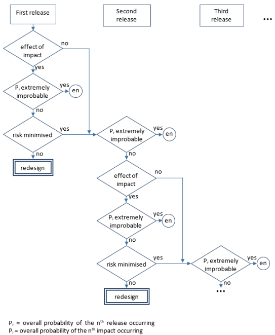
Figure 1: Methodology for the cascading failure evaluation for Category Basic 3
2. For Category Enhanced
(a) Fragments to consider:
A failure of a lift/thrust unit or other rotating-machinery should be assumed. The Safety Analysis should consider all fragments that are released with residual energy. For propellers this could be the complete blade from the aerofoil surface to the retention and any component attached to the blade/hub. This could include counterweights, clamps, erosion shields, cuffs, de-ice boots, and pitch change pins.
(b) Path and size of fragments:
For turbine engines, the paths and sizes of fragments described in AMC 20-128A and AMC 25.963(e) in Book 2 of CS-25 Amdt. 24 can be used. For propellers and other types of fragments the impact area should be established based on test, analysis, or both. Applicants may use data from propellers with similar physical and operating characteristics to establish the impact area.
(c) Hazards:
Hazards from the failure of a lift/thrust unit or other rotating-machinery to be considered should include damage due to the impact of the high-energy fragments and the imbalance created by such failure. Further guidance material on engine imbalance, including windmilling considerations, can be found in AMC 25-24. Applicants may utilize design means of control and the stoppage of those lift/thrust units, for which the probability of failure of those control means is shown to be commensurate with the objectives of VTOL.2510, and should rationally consider the environment of operation under the expected imbalance conditions.
(d) Safety Analysis:
(1) It should be assessed that the failure of a lift/thrust unit or rotating-machinery does not have a catastrophic effect as defined in MOC VTOL.2510.
(2) The assessment should include aircraft systems, structures (including energy storage), occupants and other lift/thrust units.
(3) Due to the distributed propulsion, the failure of a lift/thrust unit may, for some architectures, potentially cause other lift/thrust failures in a chain reaction. Specifically, the assessment of simultaneous or cascading failures of lift/thrust units through fragment release should use the following methodology:
(i) The first release shall not have an immediate catastrophic effect, that is:
(A) no catastrophic effect due to the lift/thrust unit failure, and
(B) no catastrophic effect due to a fragment impact into systems, structure, occupants or other lift/thrust units.
(ii) The first release may however have a catastrophic effect by cascading events if extremely improbable. This is determined as follows:
(A) If the first impact can cause a second release of a fragment from a lift/thrust unit, the probability of the second release should be evaluated.
(B) In the determination of the overall probability of the second release, consideration can be given to the probability of occurrence of the first release and the probability of chain reaction (incl. hazardous trajectory probability and associated second release probability).
(C) If this overall probability of the second release (Pr) is less than 10-9 per flight hour, the hazards can be considered to have been minimised and the analysis can stop there.
(D) If this overall probability of the second release (Pr) is higher than 10-9 per flight hour, the effect of the second impact should be assessed:
(a) If the effect of the second impact is catastrophic, it must be extremely improbable ( per flight hour).
(b) If the effect of the second impact is not catastrophic, the overall probability of the third release should then be evaluated.
(E) The analysis should continue until the overall probability of the next release (Pr) or impact (Pi) is less than  per flight hour, or all lift/thrust units have been assessed (Figure 2).
(iii) The residual risk for each lift/thrust unit and the whole aircraft should then be quantified to verify that the combined risks do not exceed an acceptable level.

Figure 2: Methodology for the cascading failure evaluation for Category Enhanced
3. Structural Failure Rate (Category Basic and Enhanced)
(a) The framework outlined in section (b) “Structural Failure Rate” of MOC VTOL.2250(c) may be used to determine the probability of occurrence of the first failure, which is then subsequently used in the cascading scenario.
(b) The qualitative approach of section (b) “Structural Failure Rate” of MOC VTOL.2250(c) cannot be used to justify a Structural Failure Rate lower that 10-7 per flight hour. All three aspects should be addressed, i.e. design robustness, quality of the part and in-service continued structural robustness, however not necessarily equally.
MOC VTOL.2240 (e) In-Service Monitoring
n/a
(a) For the purpose of VTOL.2240(e) parts having an important bearing on safety in operations are parts the failure of which has hazardous or catastrophic effects for the aircraft.
(b) The provisions for In-Service Monitoring established in compliance with VTOL.2240(e) should include the necessary means to verify the health and operating conditions to help ensure the continued durability, integrity and functionality of the part. Actions arising from a finding could in the future change the certification approach for similar components or lead to continued airworthiness action.
(c) The applicant should define an In-Service Monitoring programme which should verify the continuity of the effectiveness of design and maintenance provisions, as well other procedures, implemented to comply with VTOL.2240(a) and (b), VTOL.2250(a) and (c) and VTOL.2625 through the life of the type design.
(d) The following means can be used to support the In-Service Monitoring programme:
(1) Analysis of occurrence reports.
(2) Analysis of unscheduled removal rates.
(3) Results of scheduled maintenance.
(4) Strip Reports / Analysis at overhaul.
(5) Post-TC development and maturity tests.
(6) Additional inspection (non-destructive and/or destructive) and testing on selected high time or rejected components.
(7) Feedback from lead customers.
(8) Audits of subcontractors and suppliers of parts.
(9) Statistical process control data of manufacturing processes that are essential to ensure the integrity and/or functionality of the part.
(10) Review of concessions.
(11) Changes in utilization and operating environment.
(12) Operator / applicant working group activities.
(13) Health monitoring data.
(14) Usage monitoring data.
(e) The assessments required by the In-Service Monitoring programme should be performed at suitable periods through the complete life of the subject component types, considering the types of operation, environment and ageing effects expected. In addition, the applicant should consider scheduling early evaluation opportunities to confirm the suitability of the inspection and/or other procedures developed under VTOL.2240. Consideration should be given to adding new samples and revising the programme when changes to the types of operation or environment occur.
(f) A plan defining the tasks and schedule of the In-Service Monitoring programme should be agreed during certification.
(g) Regular reports stating the findings of the In-Service Monitoring programme during service should be furnished to the Agency, assessing all findings made.
n/a
(a) The aircraft must be free from flutter, control reversal, and divergence:
(1) at all speeds within and sufficiently beyond the structural design envelope;
(2) for any configuration and condition of operation;
(3) accounting for critical degrees of freedom; and
(4) accounting for any critical failures or malfunctions.
(b) The applicants' design must account for tolerances for all quantities that affect flutter.
n/a
(a) General. The aeroelastic stability evaluations referred to in this MOC include flutter, divergence, control reversal and any undue loss of stability and control as a result of structural deformation. The aeroelastic evaluation should include whirl modes associated with any lift/thrust unit or other rotating devices that contribute to significant dynamic forces. Compliance with this paragraph should be shown by analyses and tests.
(b) Aeroelastic stability envelopes. The aircraft should be designed to be free from aeroelastic instability for all configurations and design conditions, including transition phases, within the aeroelastic stability envelopes as follows:
(1) For normal conditions without failures, malfunctions, or adverse conditions, all combinations of altitudes and speeds encompassed by the VD versus altitude envelope, enlarged at all points by an increase of 20 percent in equivalent airspeed at constant altitude, should be considered. In addition, a proper margin of stability should exist at all speeds up to VD and there should be no large and rapid reduction in stability as VD is approached.
(2) For the conditions described in (c) below, for all approved altitudes, any airspeed up to VD should be considered.
(3) Failure conditions of certain systems should be treated in accordance with VTOL.2205. For these failure conditions, the speed clearances defined in MOC VTOL.2205 Figure 3 apply.
(c) Failures, malfunctions, and adverse conditions. The failures, malfunctions, and adverse conditions which should be considered are:
(1) For aircraft with disposable fuel: critical fuel loading conditions not shown to be extremely improbable which may result from mismanagement of fuel
(2) Single failures, malfunctions, or disconnections, and any combination of these that is not extremely improbable, of elements in the primary flight control system, tab control system, or flutter damper
(3) Failure of any single element of the structure supporting any engine, lift/thrust unit, shaft, or large externally mounted aerodynamic body
(4) Failures of any single element of the lift/thrust unit structure that would affect the aeroelastic characteristics of the aircraft
(5) Any lift/thrust unit or rotating device capable of significant dynamic forces rotating at the highest likely overspeed
(6) Any damage or failure conditions, required or selected for investigation by VTOL.2240 (a) and (b)
(7) Any other combination of failures, malfunctions, or adverse conditions not shown to be extremely improbable.
(d) Flight flutter tests should be made to show that the aircraft is free from flutter, control reversal and divergence and to show by these tests that:
(1) Proper and adequate attempts to induce flutter have been made within the speed range up to VD;
(2) The vibratory response of the structure during the test indicates freedom from flutter;
(3) A proper margin of damping exists at VD; and
(4) There is no large and rapid reduction in damping as VD is approached.
(e) For modifications of the type design which could affect the flutter characteristics, compliance with (a) should be shown, except that analysis alone, which is based on previously approved data, may be used to show freedom from flutter, control reversal and divergence for all speeds up to the speed specified for the selected method.
VTOL.2250 Design and construction principles
n/a
(a) Each part, article, and assembly must be designed for the expected operating conditions of the aircraft.
(b) Design data must adequately define the part, article, or assembly configuration, its design features, and any materials and processes used.
(c) The applicant must determine the suitability of each design detail and part having an important bearing on safety in operations. The applicant must prevent single failures from resulting in a catastrophic effect upon the aircraft.
(d) The control system must be free from jamming, excessive friction, and excessive deflection when the aircraft is subjected to expected limit air loads.
(e) Doors, canopies, and exits must be protected against inadvertent opening in flight, unless shown to create no hazard, when opened in flight.
(f) The aircraft must be designed to ensure that after a likely bird impact the capability remains to conduct:
(1) a controlled emergency landing for Category Basic with a maximum passenger seating configuration of 7 or more; or
(2) continued safe flight and landing for Category Enhanced.
MOC VTOL.2250(c) No catastrophic effect from structural single failures in the Category Enhanced
n/a
The following method is accepted for compliance with VTOL.2250(c) in the Category Enhanced for structural elements and parts:
(1) a complete and comprehensive list of structural elements or parts and their interfaces should be provided;
(2) the functions that the structural elements or parts perform should be identified; and
(3) a safety assessment should be performed to identify all structural elements and parts for which failure could lead to Catastrophic consequences. All reasonably anticipated and conceivable failure modes should be taken into account without considering mitigation means, and all the stages of flight and operating conditions should be considered.
(4) The conclusions of the Safety Assessment should demonstrate the non-catastrophic classifications of all single failures and thereby show direct compliance with VTOL.2250 (c).
(5) If any single failure is identified that can lead to a catastrophic consequence:
(i) a structural redesign or vehicle re-configuration should be considered.
(b) Structural Failure Rate
For structural elements or parts and failure modes identified in (a)(5)(ii), if a quantitative assessment is not directly feasible, an acceptable combination of compensating provisions should be implemented that provides sufficient confidence to achieve the safety objective and is appropriate to address the failure mode that could result in catastrophic consequences.
In addition, the framework outlined below may be used to determine the Structural Failure Rate for the MOC VTOL.2240(d) assessment, if a quantitative assessment is not directly feasible.
It should address each of the three following aspects (1) to (3), for which a non-exhaustive list of examples is provided below for each aspect:
(1) Design Robustness:
(i) Larger static safety margins
(ii) Thorough proven understanding of the load distribution
(iii) Natural frequencies far from the forcing frequencies
(iv) Larger fatigue (safe life) margins
(v) Damage tolerance demonstration of larger damages
(vi) Low complexity of the design and a limited number of failure modes
(vii) Design values based on a statistical A-basis (99% probability with 95% confidence) as a minimum
(2) Quality of the part
(i) Identification of key manufacturing parameters and processes that are strictly controlled, the modification of which require OEM validation.
(ii) Regular material batch testing throughout the life of the element or part
(iii) Non-destructive tests (NDT) / Destructive tests (DT) of one sample from every batch throughout the life of the element or part
(iv) Non-destructive acceptance test of every article
(v) Process control specimens or witness coupons
(vi) Special assembly procedures or functional tests to avoid maintenance errors
(vii) Sensitivity to production process variability is low or is taken into account in the design
(3) In-Service Continued Structural Robustness
(i) Regular non-destructive inspections (NDI)
(ii) Limited repairs permitted without TC Holder support
(iii) End of flight reports of relevant parameters, for example, vibration, loads, deflection, temperature, acoustic emission
(iv) Active in-flight monitoring with pilot notification
(v) In-Service Monitoring to verify the health and operating conditions and the effectiveness of design and maintenance provisions, as well as other procedures, throughout the life of the type design., refer to MOC VTOL.2240(e)
(vi) Health and Usage Monitoring System (HUMS), refer to MOC VTOL.2240(e)
(vii) Notification required to the TC Holder of any unusual or unexpected wear or deterioration of parts in service
For some elements the determination of the failure rate could be more appropriately determined using other cycles, such as flight cycles or centrifugal force cycles. A conservative spectrum should then be used to convert the structural failure rate into probability per flight hour.
(c) In the safety assessment in (a)(3) of this MOC related to bearings, as a minimum and when applicable, the following failure modes of bearings should be considered:
(1) rupture of one or several of the bearing constituents
(2) partial or complete seizure of the bearing
(3) advanced spalling of bearings races or rolling elements
(4) advanced wear of bearing rings, rolling elements or cages
(5) loss of bearing preload
(6) permanent deformation
MOC VTOL.2250(e) Doors, canopies and exits
n/a
(a) This paragraph applies to: All doors, hatches, openable windows, access panels, covers, etc., on the exterior of the vehicle.
(b) However, this paragraph does not apply if the door requires a specific tool to both open and close the door.
(c) This paragraph also does not apply if the opening of the door, in any flight phase, would not cause an event worse than Minor, as defined in VTOL.2510. The potential of persons inadvertently falling from the vehicle, and the physiological effect on passengers, should be included in the event classification, in addition to any effects on the vehicle structure, systems, controllability etc.
(d) Latches are movable mechanical elements that, when engaged, prevent the door from opening.
(e) Latched means the latches are engaged with their structural counterparts and held in position by the latch operating mechanism.
(f) Structural aspects of Door design, and Emergency Egress from the vehicle are out of scope of this paragraph. Refer to VTOL.2315(a) for emergency egress and Subpart C for the structural aspects.
2. Relevance to ASTM F3061 – 16a
(a) Paragraph 13.11.1 should be applicable, and complements Section 4 below.
(b) Paragraph 13.11.9 could be a means of compliance to Section 4 below, but need not be a separate point.
3. Occupant Retention
A seatbelt, or other occupant retention device, should not be considered an adequate alternative or mitigation against compliance with this paragraph.
4. Door Latching
(a) For all doors within the scope of this paragraph, there should be means for latching and for preventing their opening in flight inadvertently or as a result of mechanical failure.
(b) Acceptable features to prevent inadvertent operation by occupants are, for example:
(1) recessing door handles; and
(2) door handles that are moved/rotated up to open the door and moved/rotated down to close the door.
(c) Means to prevent inadvertent door opening in flight due to "mechanical failure" should be provided through multiple door latches and multiple load path door locking mechanisms so that the door will remain locked after a single failure.
(d) Care should be taken in the design of multiple load path latches and mechanisms to assure independence of all failures to consider the consequences of common-mode failures and errors, and to consider the effort of deflections after failures (if a failure allows deflections into the airstream sufficient to increase aerodynamic loads, the increase in loads should be accounted for; if a failure allows significant movement of latching components, the deflections should be accurately accounted for to assure that disengagement of non-failed latches does not occur).
5. Direct Visual Inspection
There should be means for direct visual inspection of the latching mechanism by flight crew members to determine whether the external doors (including passenger, crew, service, and cargo doors) are fully latched.
6. Flight Crew Indication
There should be visual means (combined with other attention-getters as appropriate, refer to MOC VTOL.2605(b) ) to signal to appropriate flight crew members when doors within the scope of this paragraph are not closed and/or not fully latched.
7. Particular Risk Aspects
The door mechanisms should be designed such that the door will not open in case of a bird strike or other Particular Risk effect.
MOC VTOL.2250(f) Aircraft capability after bird impact
n/a
This MOC provides methods to demonstrate the remaining capability of the aircraft after a bird impact as required by VTOL.2250(f).
It is applicable to VTOL capable Aircraft in the Category Basic designed to carry 7 to 9 passengers and in the Category Enhanced.
1. Single bird strike evaluation:
(a) In accordance with VTOL.2250(f), VTOL capable aircraft must be designed to ensure the capability of a controlled emergency landing in the Category Basic with a maximum of 7 or more seats, or of a continued safe flight and landing in the Category Enhanced, after impact of a 1.0-kg (2.2-lb) bird. This should be ensured in the most critical configuration for the corresponding velocity of the VTOL (relative to the bird along the flight path of the vehicle) up to the maximum speed in level flight with maximum continuous power, at operating altitude up to 2438 m (8,000 ft.).
(b) Compliance should be shown by tests or by analysis based on tests carried out on sufficiently representative structures of a similar design.
(c) The following parts should be evaluated for a single bird strike:
(1) The windshield directly in front of occupants and the supporting structures for these panels should be capable of withstanding a bird impact without penetration for maximum speeds above 50kt.
(2) Other structures, systems and equipment should also be evaluated. The selection of the areas to be substantiated should be the result of a comprehensive hazard analysis based on:
(i) Exposed areas of the structure and internal equipment and systems inside of these exposed areas in case of bird penetration or shock loads; and
(ii) Their criticality and their ability to ensure continued safe flight and landing (for Category Enhanced) or controlled emergency landing (for Category Basic).
(d) When performing the hazard analysis, direct and induced effects of a bird strike should be considered:
(1) "Direct Effects": to ensure the integrity of the structure and functionality of systems or equipment (including consideration of shock loads) which are critical for continued safe flight and landing (for Category Enhanced) or controlled emergency landing (for Category Basic).
(2) "Induced Effects": to examine the possible consequences of the ejection of pieces from structures, systems or equipment which are struck by a bird on other structures and systems. For a bird impact on the lift/thrust system, the guidance in MOC VTOL.2240(d) can be followed, when relevant, in the demonstration of compliance mentioned in paragraph (a) of this section.
2. Multiple bird strike evaluation:
(a) VTOLs are generally equipped with redundant systems and structures. To ensure continued safe flight and landing (for Category Enhanced) or controlled emergency landing (for Category Basic) following a multiple bird strike, an evaluation should be performed of the effects of such multiple bird strike in the most critical configurations for the corresponding velocity of the VTOL up to the maximum speed in level flight with maximum continuous power, within the range of airspeed for normal operation up to 4000ft MSL (Mean sea level).
(b) The applicant should consider potentially vulnerable redundant systems and structures and their effective exposed area (wing, lift surfaces, rudder, ailerons…).
(c) An acceptable approach is to show that there is no loss of function of the element that is impacted after a single impact with a medium sized bird of 0.450 kg. Alternatively, scenarios evaluating multiple bird impacts distributed across each structure or system can be proposed by the applicant considering medium birds and small birds according to the MOC VTOL.2400 guidance (see Figure 1). Multiple bird strike evaluation is not required for the windshield.

Figure 1- Overview of the Airframe and Propulsion System guidance interaction for compliance to bird strike
VTOL.2255 Protection of structure
n/a
(a) Each part of the aircraft, including small parts such as fasteners, must be protected against deterioration or loss of strength due to any cause likely to occur in the expected operational environment.
(b) Each part of the aircraft must have adequate provisions for ventilation and drainage.
(c) For each part that requires maintenance, preventive maintenance, or servicing, the applicant must incorporate a means into the aircraft design to allow such actions to be accomplished.
MOC VTOL.2255 Protection of structure
n/a
(a) The following combination of CS-27 Amdt. 6 requirements, with their corresponding guidance material, is accepted as a means of compliance with VTOL.2255:
|
SC VTOL |
CS -27 Amdt. 6 |
|
VTOL.2255 (a) |
CS 27.609 (a) Protection of Structure CS 27.607 (a) Fastener |
|
VTOL.2255 (b) |
CS 27.609 (b) Protection of Structure |
|
VTOL.2255 (c) |
CS 27.611 Inspection provisions |
(b) For composite structures, additional guidance can be found in AMC 20-29 chapter 6.d. and 6.e and in MOC VTOL.2240 (a) & (b).
VTOL.2260 Materials and processes
n/a
(a) The applicant must determine the suitability and durability of materials used for parts, articles, and assemblies, the failure of which could prevent continued safe flight and landing for Category Enhanced, or a controlled emergency landing for Category Basic, accounting for the effects of likely environmental conditions expected in service.
(b) The methods and processes of fabrication and assembly used must produce consistently sound structures. If a fabrication process requires close control to reach this objective, the applicant must define the process with an approved process specification as part of the design data.
(c) Except as provided for in VTOL.2260(f) and (g), the applicant must select design values that ensure material strength with probabilities that account for the criticality of the structural element. Design values must account for the probability of structural failure due to material variability.
(d) If material strength properties are required, a determination of those properties must be based on sufficient tests of material meeting specifications to establish design values on a statistical basis.
(e) If environmental effects are significant on a critical component or structure under normal operating conditions, the applicant must determine those effects.
(f) Design values, greater than the minimums specified by VTOL.2260, may be used, where only guaranteed minimum values are normally allowed, if a specimen of each individual item is tested before use to determine that the actual strength properties of that particular item will equal or exceed those used in the design.
(g) An applicant may use other material design values if specifically approved by the Agency.
MOC VTOL.2260 Materials and processes
n/a
(a) The following combination of CS-27 Amdt. 6 requirements, with their corresponding guidance material, is accepted as a means of compliance with VTOL.2260:
|
SC-VTOL |
CS-27 Amdt. 6 |
|
VTOL.2260 (a) |
CS 27.603 Material CS 27.613 (c) Material strength properties and design values |
|
VTOL.2260 (b) |
CS 27.605 Fabrication methods |
|
VTOL.2260 (c) |
CS 27.613 (a) & (b) Material strength properties and design values |
|
VTOL.2260 (d) |
CS 27.613 (a) Material strength properties and design values |
|
VTOL.2260 (e) |
CS 27.603 (c) Materials |
|
VTOL.2260 (f) |
CS 27.613 (e) Material strength properties and design values |
|
VTOL.2260 (g) |
CS 27.613 Material strength properties and design values |
(b) For composite structures, additional guidance can be found in AMC 20-29 chapter 6 and MOC VTOL.2240 (a) & (b).
(c) For additive manufacturing, additional guidance can be found in the EASA Certification Memorandum CM-S-008.
VTOL.2265 Special factors of safety
n/a
(a) The applicant must determine a special factor of safety for each critical design value for each part, article, or assembly for which that critical design value is uncertain, and for each part, article, or assembly that is:
(1) likely to deteriorate in service before normal replacement; or
(2) subject to appreciable variability because of uncertainties in manufacturing processes or inspection methods.
(b) The applicant must determine a special factor of safety using quality controls and specifications that account for each:
(1) type of application;
(2) inspection method;
(3) structural test requirement;
(4) sampling percentage; and
(5) process and material control.
(c) The applicant must multiply the highest pertinent special factor of safety in the design for each part of the structure by each limit load and ultimate load, or ultimate load only, if there is no corresponding limit load, such as occurs with emergency condition loading.
MOC VTOL.2265 Special factors of safety
n/a
(a) The following combination of CS-27 Amdt. 6 requirements, with their corresponding guidance material, is accepted as a means of compliance with VTOL.2265:
|
SC-VTOL |
CS-27 Amdt. 6 |
|
VTOL.2265 (a) |
CS 27.619(a) Special factors CS 27.621 Casting factors CS 27.785 (h) & (k) |
|
VTOL.2265 (b) |
CS 27.619 Special factors CS 27.621 Casting factors CS 27.623 Bearing factors CS 27.625 Fitting factors CS 27.785 (h)&(k) Seats, berths, safety belts, and harnesses |
|
VTOL.2265 (c) |
CS 27.619, applicable to limit (if any) and ultimate load conditions |
(b) For items of mass which are subjected to frequent removal: In order to ensure the strength of the components throughout the service life despite the deterioration through frequent removal, an additional factor in accordance with CS 27.619(a)(2) should be applied to all loading conditions. The local attachments for these items should be designed to withstand 1,33 times the specified loads if these items are subject to severe wear and tear through frequent removal.
(c) For composite structure, additional guidance can be found in AMC 20-29.
(d) For additive manufacturing, additional guidance can be found in the EASA Certification Memorandum CM-S-008.