ED Decision 2013/011/R
The suitability of each design detail or part that bears on safety is established by tests or analysis.
ED Decision 2013/011/R
The suitability and durability of materials used for parts, the failure of which could adversely affect safety:
(a) are established by experience or tests; and
(b) meet approved specifications that ensure that the materials have the strength and other properties assumed in the design data.
ED Decision 2013/011/R
Approved specifications here are taken as being those produced by the applicant or those meeting internationally recognised standards as defined applicable in the type design data. Material specifications are those contained in documents accepted either specifically by the Agency or by having been prepared by an organisation or person which the Agency accepts has the necessary capabilities. In defining design properties, these material specification values are modified and/or extended as necessary by the constructor to take account of manufacturing practices (for example method of construction, forming, machining and subsequent heat treatment). Also the effects of environmental conditions, such as temperature and humidity expected in service, are taken into account.
CS 31TGB.35 Fabrication methods
ED Decision 2013/011/R
The methods of fabrication used produces a consistently sound structure. If a fabrication process requires close control to reach this objective, the process is performed in accordance with an approved process specification.
AMC1 31TGB.35 Fabrication methods
ED Decision 2013/011/R
Approved fabrication methods here are taken as being those produced by the applicant or those meeting internationally recognised standards as defined in the applicable type design data. Fabrication methods are those contained in documents accepted either specifically by the Agency or by having been prepared by an organisation or person which the Agency accepts has the necessary capabilities.
CS 31TGB.36 Stress concentrations
ED Decision 2013/011/R
The structure is designed to avoid, as far as practicable, points of stress concentration and variable stresses that would cause fatigue to occur in normal operation.
ED Decision 2013/011/R
(a) Fasteners (e.g. bolts, pins, screws, karabiners) used in the structure conform to approved specifications.
(b) Locking methods are established and documented.
(c) Unless a joint is free from relative movement, secondary locking means are used.
(d) Self-locking nuts are not used on bolts that are subject to rotation in service.
ED Decision 2013/011/R
Approved specifications in the sense of these requirements are the standards described in the AMC1 31TGB.33(b).
CS 31TGB.39 Protection of parts
ED Decision 2013/011/R
Parts, the failure of which could adversely affect safety, are suitably protected against deterioration or loss of strength in service due to weathering, corrosion, heat, abrasion, ground handling, ground transport, flight conditions or other causes.
AMC1 31TGB.39 Protection of parts
ED Decision 2013/011/R
Suspension system cables and components manufactured from stainless steels (corrosion resistant steels) are considered compliant with this requirement.
To ensure the protection of parts, it is permissible to rely on recommended inspections (details in the Maintenance Manual).
In cases where deterioration or loss of strength is unavoidable during the life of the product, details of appropriate mandatory replacement lives or in-service testing are provided in the maintenance programme (CS 31TGB.82).
CS 31TGB.41 Inspection provisions
ED Decision 2013/011/R
There are means to allow close examination of each part that requires repeated inspection and adjustment.
CS 31TGB.43 Balloon system controls
ED Decision 2013/011/R
(a) Each control can be operated easily, smoothly, and positively to allow proper performance of its functions. Controls are arranged and identified to prevent confusion or inadvertent operations.
(b) Each control system and operating device is designed and installed in a manner that will prevent jamming, chafing, or unintended interference from passengers or loose items of equipment. The elements of the control system have design features or are distinctly and permanently marked to minimise the possibility of incorrect assembly that could result in failure of the control system.
(c) Control cords
(1) General
(i) All control cords used for flight control are designed and installed to preclude entanglement and inadvertent operation.
(ii) The maximum force required for their operation does not exceed 340 N.
(iii) All control cords used for flight control are long enough to allow an increase of at least 10 % in the vertical dimension of the envelope.
(iv) Arming cords. If an arming device is employed to prevent inadvertent operation of an irreversible control, the part of the device to be handled by the operator is coloured with yellow and black bands.
(2) Venting cords
(i) If a venting cord is used to allow controlled release of the lifting gas and the vent can be resealed in flight, the part of the cord to be handled by the operator is coloured with red and white bands.
(ii) If a further cord is required to re-seal any vent, the part of the cord handled by the operator is coloured white.
(3) Rapid or emergency deflation cords.
(i) If a cord is used for rapid or emergency deflation of the envelope and the device cannot be resealed in flight, the part of the cord to be handled by the operator is coloured red.
(ii) In addition to subparagraph CS 31TGB.43(c)(1)(ii) the force required to operate the emergency deflation cord is not less than 110 N.
CS 31TGB.45 Protection of envelope against tearing
ED Decision 2013/011/R
The design of the envelope is such that, while supporting limit load, local damage will not grow to an extent that results in an uncontrolled landing.
AMC1 31TGB.45 Protection of envelope against tearing
ED Decision 2013/011/R
Demonstration of sufficient rip-stopping capability of the envelope material.
The objective of this demonstration is to show that the envelope material is sufficiently damage resistant. It therefore needs to be determined that the envelope material would not continue to tear under the maximum tension and conditions (temperature) experienced in normal operation.
In order to establish that the determined damage resistance is sufficient, the critical damage should be reviewed in relation to local damage foreseeable in normal operation.
The local damages to be considered are:
existing damage that may be undetected during pre-flight inspection, and
limited damage, inflicted during flight where the size of the damage in itself would not result in a catastrophic failure.
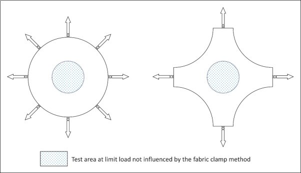
The resistance of envelope fabric to damage propagation is determined by test.
It is shown by test that a crosswise slit of at least 5 cm in the most unfavourable direction to the envelope fabric at the maximum tension experienced in service does not propagate. Test results from tests on similar fabric at the equal or higher tension and damage equal or larger than 5 cm are considered compliant.
A typical test set-up is provided below.
The tension in the test area of the specimen of the fabric should be equal to the maximum tension experienced in service and the test method should not create unacceptable tension re-distributions in the test area when the test is conducted.
If the balloon is equipped with a net to distribute and reduce the loads in the envelope, the net is regarded as a tear-prevention device.
CS 31TGB.47 Precautions against loss of lifting gas
ED Decision 2013/011/R
The envelope is designed to exclude the possibility of loss of lifting gas likely to adversely affect safe operation taking into account dynamic pressure, temperature and fluctuations in air pressure over the permissible operating range.
CS 31TGB.49 Limiting the operating pressure
ED Decision 2013/011/R
The balloon is equipped with an automatic and/or manual lifting gas release device. The response pressure of an automatic pressure release device is established. The quantity of gas to be released by the pressure release device is large enough to prevent a further increase in pressure. Opening of a pressure relief device is unambiguously indicated to the operator.
AMC1 31TGB.49 Limiting of operating pressure
ED Decision 2013/011/R
The envelope pressure is limited to prevent the envelope from bursting. However, the definition of the envelope's maximum operating pressure depends on the design of the tethered gas balloon system. For inflated balloon systems the operating conditions are not limited to flight but also include the parking conditions if the balloon system stays inflated for a prolonged period between the flight operations. Thus, different cases need to be considered:
(a) Balloon systems staying inflated above maximum wind speed for flight operation
These balloon systems ensure envelope tautness by a ballonet or other means of feeding/discharging gas into the envelope when moored on the ground in parking position to withstand the dynamic pressure of considerably high wind speeds. Here the maximum operating pressure is the maximum pressure established by the designer for high wind speeds whilst moored in parking condition to the ground. Under this condition the safety factors in CS 31TGB.25 are applicable. The ascent factor in CS 31TGB.23(b) is however not applicable in the parking position. The response pressure of the automatic lifting gas release valve usually is higher than the maximum operating pressure to prevent the envelope from getting pumped out below dynamic pressure of the wind by unexpected gusts. A factor of not less than 1·4 times the maximum operating pressure during mooring has been shown by practical experience to be applicable.
(b) Balloon systems other than described in (a)
These balloon systems are usually smaller and ensure envelope tautness by means other than described under (a), i.e. by flexible parts in the envelope. They are designed for maximum wind speed during flight operation and will normally be deflated during high wind speed weather conditions. Here the maximum operating pressure is the pressure for flight operation established by the designer. The response pressure of the automatic lifting gas release device is not less than 1·15 times the maximum operating pressure.
For clarification, it should be noted that in a strict sense the automatic pressure release device can only prevent the further rise of pressure for the very moment. After release the device should close again in order to minimise the loss of lifting gas. If after a while the pressure increases again for any reason, the device will also open again. This behaviour is intended and does not impair safety.
CS 31TGB.51 Rapid deflation means
ED Decision 2013/011/R
The envelope has a means allowing rapid deflation of the balloon.
AMC1 31TGB.51 Rapid deflation means
ED Decision 2013/011/R
Rapid deflation means are used to deflate the envelope in cases like e.g. when:
wind speeds increase above the wind speed limitations for low mooring;
required during inflation before attachment of the tether cable; or
included in emergency procedures for unintended free flight.
Note: The rapid deflation means for low mooring acts automatically when the balloon is not being monitored by an operator.
ED Decision 2013/011/R
(a) The suitability, durability, and reliability of the tether system is established for all phases of operating.
(b) In operation and mooring the balloon is securely and reliably anchored to the ground.
(c) Precautions are to be taken to mitigate the risks due to the effect of wind exceeding the maximum wind speed stated in the Flight Manual on the balloon when moored to the ground.
AMC1 31TGB.53(a) Tether system
ED Decision 2013/011/R
The suitability, durability, and reliability of the tether system, including the tether control systems, is determined by a Failure Mode Effect Analyses (FMEA) covering all phases of operation.
For components of the tether system (i.e. the winch) compliance with the requirement of CS 31TGB.53(a) can be shown by a certificate from an expert body provided that:
(a) this certificate specifies the conditions for safe operation of the winch that cover the conditions for safe operation of the balloon;
(b) the winch system is capable of safely fulfilling the task of a tethered gas balloon winch;
(c) compliance with the Machinery Directive 2006/42/EC (or equivalent (US) requirements) is the basis for the tethered gas balloon winch system;
(d) modifications to the winch design do not invalidate the applicable requirements from the certificate that remain applicable after the modification.
Note: The overload protection of industrial winches is not applicable in the TGB application because overload cannot occur in a TGB application;
(e) the expert body is an EC-notified organisation which has a certified structure and a proven capability and experience. ‘Certified’ means an approval by the government which requires an organisational structure and entails extended liability. ‘Proven capability’ means successfully managed projects that are reasonably comparable to the balloon winch case. Usually these are cranes, elevators, rides or similar winch technology;
(f) the final report complies with the Annex II of the Machinery Directive 2006/42/EC (or equivalent (US) requirement); and
(g) there is an alternative retrieve system which is able to cover a functional failure of the winch.
AMC1 31TGB.53(c) Tether system
ED Decision 2013/011/R
An automatic rapid deflation (See CS 31TGB.51) of the balloon in case it breaks away from its low mooring position or any other system that will prevent uncontrolled free flight is an acceptable risk mitigation.
ED Decision 2013/011/R
(a) The gondola may not rotate independently of the envelope unless safe operation is assured.
(b) Projecting object in the gondola, that could cause injury to the occupants, are avoided or padded.
(c) A holding grip is provided for each occupant.
(d) Reasonable space is provided for all occupants, with regard to both comfort during the flight and to safety during the landing.
(e) Occupants and items in the gondola are prevented from falling from the gondola.
(f) The gondola occupant securing devices (e.g. doors or harnesses) comply with the following requirements:
(1) The device is closed and locked during flight.
(2) The device is protected against unintentional opening by persons or opening as the result of a mechanical failure during flight.
(2) The device can be opened by occupants and crew.
(3) Operation of the device shall be simple and obvious.
(4) The device has a visual indication that it is properly closed and locked.
ED Decision 2013/011/R
The requirements for a gondola carrying multiple free-standing persons is complied with when the applicable requirements for the ‘carrier’ provided in the Machinery Directive 2006/42/EC are met.
ED Decision 2013/011/R
A holding grip provides an obvious means for the occupants of the gondola to stabilise themselves during flight. The location or design of occupant securing devices (refer to CS 31TGB.59(f)(1)) is such that they do not invite occupants to use them as holding grip.
ED Decision 2013/011/R
For gondola providing standing space for the occupant, a minimum plan area of 0·3 m² is provided for each occupant.
ED Decision 2013/011/R
(a) If the balloon is operated at night, illumination of controls, equipment and essential information is provided for the safe operation of the balloon.
(b) An Anti-Collision light system is installed which complies with the following:
(1) The Anti-Collision light consists of one or more flashing red (or flashing white) light(s) with an effective flash frequency of at least 40, but not more than 140, cycles per minute.
(2) The Anti-Collision light arrangement provides 360° horizontal coverage and at least 60° vertical coverage above and below the horizontal plane.
(3) The Anti-Collision light(s) are mounted on, or suspended from the balloon in order to identify the position of the envelope and gondola during night operation.
(4) At least one Anti-Collision light is visible from a distance between 100 m and 3 700 m (2 NM) at night under clear atmospheric conditions.
(5) The Anti-Collision light system can be switched on/off during flight.
(c) The night lighting will not impair the crews’ vision or performance during operation.
AMC1 31TGB.65(a) Night lighting
ED Decision 2013/011/R
A means to provide illumination of the instruments, equipment and controls that are essential for the safe operation of the balloon may be instrument lighting, local lighting or any independent portable (non-handheld) light of sufficient capacity.
It is acceptable that lights can be switch on and off provided that the operator, without undue burden or ambiguity, can switch on the lighting in night conditions.
AMC1 31TGB.65(b) Night lighting
ED Decision 2013/011/R
The following two schematics illustrations for anti-collision light arrangements show vertical coverage and positions that meet the requirements of CS 31TGB.65(b)(2) and (3).
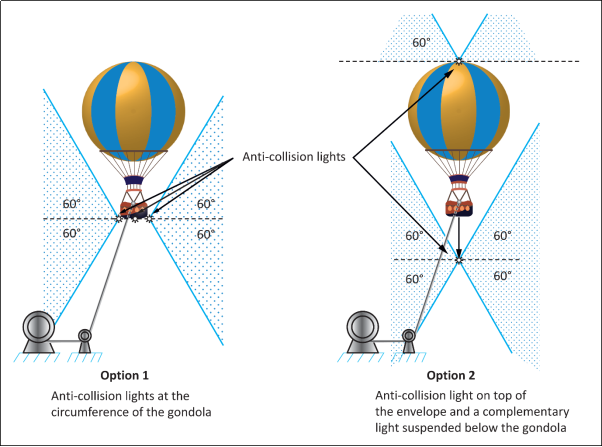
The horizontal 360° coverage requirement is applicable to a distance between 100 m and 3 700 m (2 NM). It is acceptable that the light from the anti-collision lights is not visible from positions closer than 100 m horizontally from the balloon.
AMC1 31TGB.65(c) Night lighting
ED Decision 2013/011/R
The light from the Anti-Collision light does not directly shine on the crew and passengers and does not create a reflection on the balloon or flare that disturbs the crews’ performance.
Lighting level of controls, equipment and instruments are compatible with the crew night vision. This prevents untimely fatigue of the eyesight due to frequent adaptation when looking from bright light into dark night and vice versa.
CS 31TGB.67 On-board power units
ED Decision 2013/011/R
If an on-board power unit is used to provide electrical power during operation, the system is designed and installed so as not to create a fire hazard or cause an electrical shock to the occupants.
AMC1 31TGB.67 On-board power units
ED Decision 2013/011/R
For this AMC, it is assumed that only power units are used which conform to the state-of-the-art industrial standard. The safe operation of the balloon is not directly dependent on the proper function of the power unit. For all other designs, the Agency is consulted for more detailed requirements.
Power units of industrial standard used on-board of the balloon in addition comply with the following:
(a) General
The power unit is designed and installed so that under all normal operating conditions and reasonably foreseeable in service emergency situations, it does not endanger the aircraft, its occupants, or third parties.
(b) Ventilation
The occupants are accommodated in adequately ventilated areas where:
(1) the carbon monoxide partial pressure does not exceed 1/20 000; and
(2) fuel vapour is not present in harmful concentrations.
(c) Fire extinguishers
(1) Unless the power unit has a fire extinguishing system by itself, there is at least one manual fire extinguisher within reach of an occupant.
(2) The following applies to manual fire extinguishers. The type and quantity of the fire extinguishing substance is appropriate to the fire extinguisher's application area. Fire extinguishers:
(i) conform to EN3 or an equivalent specification acceptable to the Agency;
(ii) have a minimum capacity of 2 kg when using dry powder, unless the capacity is otherwise determined by the applicant; and
(iii) be at least of comparable effect when the extinguishing means is other than ‘dry powder’.
(3) Fire extinguishers in compartments intended for persons are designed to minimise the risk of toxicity caused by use of the fire extinguishing substance.
(d) Gondola
The following applies to the gondola when an on-board power unit is carried:
(1) The material used is at least fire retardant.
(2) Pipes, tanks or equipment that carries fuel, oil or flammable liquids are not to be placed in the gondola unless they are reasonably shielded, insulated, or otherwise protected so that fracture or failure of such parts causes no danger.
(e) Electrical earth connection
(1) In order to prevent the occurrence of potential differences between components of the power unit and other electrically conductive parts of the balloon which cannot be ignored on account of their mass, such conductive parts are conductively interconnected.
(2) The cross-sectional area of bonding connectors, if made from copper, is not less than 1·33 mm².
(f) Fire protection for control system and structure
Control systems, suspension units or other structures in the power unit compartment which are added to the design by the applicant are made of fireproof material or shielded to withstand the effect of a fire.
(g) Fire protection
(1) The power unit is adequately separated from the balloon's structure by fireproof bulkheads or ventilated bays.
(2) Areas in which combustible liquids can accumulate as a result of a leaking tank have an adequate drain pipe. Collected leaking liquids cannot reach other locations in and under the craft which pose a potential risk of fire.
(3) Precautionary measures are to be taken to reduce as far as possible the risk of fire as a result of a hard landing of the gondola.
(h) Power unit installation
(1) Each power unit is supported so that the loads resulting from the weight of the unit are not concentrated.
(2) There are pads, if necessary, to prevent chafing between each unit and its supports.
(3) Materials employed for supporting the unit or padding the supporting members are non-absorbent or treated to prevent the absorption of fuel.
(4) Each installation is ventilated and drained to prevent accumulation of flammable fluids and vapours.
(i) Fuel tank expansion space
(1) Each external fuel tank added to the design by the applicant has an expansion space of sufficient capacity, but of not less than 2 % of the tank capacity, to prevent spillage of fuel onto the surfaces of the power unit and the balloon's structure due to thermal expansion or manoeuvre unless the design of the venting system precludes such spillage.
(2) It is not possible to fill the expansion space inadvertently with the power unit in any normal ground attitude.
(j) Exhaust system, general
(1) The exhaust system ensures safe disposal of exhaust gases without fire hazard or carbon monoxide contamination in any personnel compartment.
(2) Each exhaust system part with a surface hot enough to ignite flammable fluids or vapours is located or shielded so that leakage from any system carrying flammable fluids or vapours will not result in a fire caused by impingement of the fluids or vapours on any part of the exhaust system, including shields for the exhaust system.
(3) All parts of the exhaust system are located sufficiently far from or separated from adjacent parts of the balloon's structure by fireproof shielding.
(4) No exhaust gases will discharge dangerously near any oil or fuel system drain.
(5) Each exhaust system component added to the design by the applicant is ventilated to prevent points of excessively high temperature.
(k) Firewalls
(1) The power unit is isolated from the rest of the balloons structure by a firewall, shroud, or equivalent means.
(2) The firewall or shroud is constructed so that no hazardous quantity of liquid, gas or flame can pass from the power unit compartment to other parts of the balloon.
(3) The firewall and shroud is fireproof and protected against corrosion or deterioration. The following materials are accepted as fireproof, when used in firewalls or shrouds, without being tested:
(i) stainless steel sheet, 0·38 mm thick;
(ii) mild steel sheet (coated with aluminium or otherwise protected against corrosion) 0·5 mm thick;
(iii) steel or copper base alloy firewall fittings.
(4) Other materials such as fire protection paint and/or putty are only used if they conform to the FAA Advisory Circular No. 20-135 or equivalent accepted specifications.
CS 31TGB.68 Master switch arrangement
ED Decision 2013/011/R
(a) There is a master switch arrangement to allow ready disconnection of electric power sources from the main bus.
(b) The point of disconnection is adjacent to the sources controlled by the switch.
(c) The master switch or its controls is installed so that the switch is easily discernible and accessible to the operator or occupant.
CS 31TGB.69 Electric cables and equipment
ED Decision 2013/011/R
(a) Each electric connecting cable has adequate capacity and is correctly routed, attached and connected so as to minimise the probability of short circuits and fire hazards.
(b) Overload protection is provided for each electrical equipment. No protective device protects more than one circuit essential to flight safety.
(c) Unless each cable installation from the battery to a circuit protective device or master switch, whichever is closer to the battery, is of such power carrying capacity that no hazardous damage will occur in the event of a short circuit, this length of cable is protected or routed in relation to parts of the balloon's structure that the risk of short circuit is minimised.
AMC1 31TGB.69(c) Electric cables and equipment
ED Decision 2013/011/R
The risk of short circuit for the electrical cable between battery and master switch is minimised when the unprotected battery to master switch cables, of an adequate capacity, have a maximum length of 0·5 m.
In any event the capacities of protected cables are such that no hazardous damage will occur to the balloon and its occupants, nor its effects to the occupants from the generation of noxious fumes, due to electrical overloading of cables before a circuit protective device will operate.