ED Decision 2009/005/R
The suitability of each design detail or part that bears on safety must be established by tests or analysis.
ED Decision 2009/005/R
(a) The suitability and durability of materials used for parts, the failure of which could adversely affect safety, must
(1) be established by experience or tests; and
(2) meet approved specifications that ensure their having the strength and other properties assumed in the design data. (See AMC 31HB.33(a)(2))
(b) Envelope materials must be shown not to support continued burning if ignited by the heater when the balloon is inflated or in flight.
ED Decision 2009/005/R
Approved specifications here should be taken as being those produced by the applicant or those meeting internationally recognised standards as defined applicable in the type design data. Material specifications should be those contained in documents accepted either specifically by the Agency or by having been prepared by an organisation or person which the Agency accepts has the necessary capabilities. In defining design properties these material specification values should be modified and/or extended as necessary by the constructor to take account of manufacturing practices (for example method of construction, forming, machining and subsequent heat treatment). Also the effects of environmental conditions, such as temperature and humidity, expected in service should be taken into account.
CS 31HB.35 Fabrication methods
ED Decision 2009/005/R
The methods of fabrication used must produce a consistently sound structure. If a fabrication process requires close control to reach this objective, the process must be performed in accordance with an approved process specification. (See AMC 31HB.35)
AMC 31HB.35 Fabrication methods
ED Decision 2009/005/R
Approved fabrication methods here should be taken as being those produced by the applicant or those meeting internationally recognised standards as defined in the applicable type design data. Fabrication methods should be those contained in documents accepted either specifically by the Agency or by having been prepared by an organisation or person which the Agency accepts has the necessary capabilities.
ED Decision 2009/005/R
(a) Fasteners (e.g. bolts, pins, screws, karabiners, fuel cell straps) used in the structure must conform to approved specifications. (See AMC 31HB.37)
(b) Locking methods must be established and documented.
(c) Unless a joint is free from relative movement, secondary locking means must be used.
(d) Self-locking nuts may not be used on bolts that are subject to rotation in service.
ED Decision 2009/005/R
Approved specifications in the sense of these requirements are the standards described in the AMC 31HB.33(a).
CS 31HB.39 Protection of parts
ED Decision 2009/005/R
Parts the failure of which could adversely affect safety must be suitably protected against deterioration or loss of strength in service due to weathering, corrosion, heat, abrasion, ground handling, ground transport, flight conditions or other causes. (See AMC 31HB.39)
AMC 31HB.39 Protection of parts
ED Decision 2009/005/R
Suspension system cables and components manufactured from stainless steels (corrosion resistant steels) are considered compliant with this requirement.
To ensure the suitable protection of parts against deterioration or loss of strength, it is permissible to rely on instructions for continued airworthiness (e.g. recommended inspections or mandatory replacement of parts) (See also CS 31HB.82).
CS 31HB.41 Inspection provisions
ED Decision 2009/005/R
There must be a means to allow close examination of each part that requires repeated inspection and adjustment.
ED Decision 2009/005/R
(a) A fitting factor of at least 1·15 must be used in the analysis of each fitting the strength of which is not proven by limit and ultimate load tests in which the actual stress conditions are simulated in the fitting and surrounding structure. This factor applies to all parts of the fitting, the means of attachment, and the bearing on the structural elements joined.
(b) Each part with an integral fitting must be treated as a fitting up to the point where the section properties become typical of the member.
(c) The fitting factor need not be used if the joint design is made in accordance with approved practices and the safety of which is based on comprehensive test data. (See AMC 31HB.43(c))
AMC 31HB.43(c) Fitting factors
ED Decision 2009/005/R
Approved practices here should be taken as being those produced by the applicant or those meeting internationally recognised standards as defined in the applicable type design data. Approved practices should be those contained in documents accepted either specifically by the Agency or by having been prepared by an organisation or person which the Agency accepts has the necessary capabilities.
CS 31HB.44 Protection of envelope against tearing
ED Decision 2011/013/R
The design of the envelope must be such that, while supporting limit load, local damage will not grow to an extent that results in uncontrolled flight or landing.
[Amdt No.: 31HB/1]
AMC 31HB.44 Protection of envelope against tearing
ED Decision 2011/013/R
Unless it can be demonstrated that basic envelope fabric has sufficient rip-stopping capability, horizontal and vertical load tapes and/or other rip-stoppers should be incorporated into the structure of the envelope so that likely tear lengths are limited to those for which level flight can be maintained. Failure of the envelope between rip-stoppers should be taken into account in the proof of the structure.
Demonstration of sufficient rip-stopping capability of the envelope fabric.
The objective of this demonstration is to show that the envelope fabric is sufficiently damage resistant. It therefore needs to be determined at what tear size the envelope fabric would continue to tear under the maximum tension and conditions (Temperature) experienced in normal operation. In this AMC this tear size is called the critical damage.
In order to establish that the determined damage resistance is sufficient, the critical damage should be reviewed in relation to local damage foreseeable in normal operation. The local damages to be considered are:
Existing damage that may be undetected during pre-flight inspection, and
Limited damage, inflicted during flight where the size of the damage in itself would not result in a catastrophic failure. (e.g. a limited damage caused by hitting a branch or other basket during take off)
The resistance of envelope fabric to damage propagation should be determined by test.
Determine the critical damage to the envelope fabric at the maximum tension experienced in service. Critical damage is the maximum damage at which growth does not occur.
Damages to be considered are:
A slit in the most unfavourable direction;
A crosswise slit in the most unfavourable directions.
Test requirements
The envelope fabric should be tested at maximum tension experienced in service. The effects of temperature on the material properties must be taken into account.
The tension in the test area of the specimen of the fabric should be equal to the maximum tension experienced in service and the test method should not create unacceptable tension re-distributions in the test area when the test is conducted.
A step-wise increase of the damage (e.g. a cut with a sharp knife) should be used to determine the critical damage size.
Between the step-wise increases of the damage, enough time should be permitted for the tension re-distribution at the damage location.
The critical damage length of the material should be recorded.
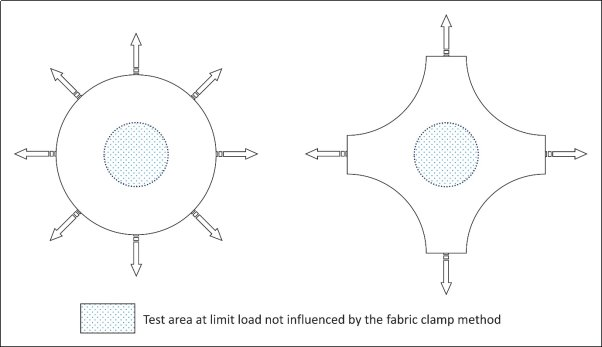
Examples of a circular or 2-directional test set-up.
Pre-flight inspection requirements
The design of the envelope and pre-flight Inspection method should be such that visible damage considerably smaller in length than the critical damage length can be detected during a pre-flight inspection. The impact of ageing and operating circumstances should be considered when establishing the margin between critical damage and detectable damage length (refer to CS 31HB.27(f)).
Design features that could possibly hinder detection of damage during a pre-flight inspection should be avoided or taken into consideration when the detectable damage length is determined.
Note 1: It is assumed that a visual pre-flight inspection will detect damage above 10 cm.
Note 2: The critical damage is a design property that should not be confused with acceptable damage as provided in the flight manual.
[Amdt No.: 31HB/1]
ED Decision 2009/005/R
(a) It must be demonstrated by test or analysis or both that fuel cell’s have sufficient strength margins to withstand all conditions of internal and external pressures, temperatures and loads likely to be encountered in operation, including during ground handling and ground transport. (See AMC 31HB.45(a))
(b) The compatibility of the cells material with the fuel must be justified. Fatigue, ageing, fire resistance and corrosion capability of the cells must be assessed and any necessary limitation, protection or maintenance action must be determined.
(c) Fuel cells, their attachments and related supporting structure must be shown by tests to be capable of withstanding, without detrimental distortion or failure, any inertia loads to which the installation may be subjected in operation. (See AMC 31HB.45(c))
(d) A pressurised fuel cell must be equipped with:
(1) A shut-off valve. This valve must be equipped with a self-sealing coupling, or other means to avoid the release of hazardous quantities of fuel should the control be inadvertently operated without a fuel line connected. (See AMC 31HB.45(d)(1))
(2) A pressure relief valve, which must protect the fuel cell against over pressurisation.
(3) A means to control the maximum filling.
(4) A means to assess the fuel quantity. (See also CS 31HB.47(c)(2))
(5) A data plate containing information necessary for safe operation. (See AMC 31HB.45(d)(5))
(e) Guards must be fitted to all fuel cells to protect the valves and other fittings from fuel leakage in case of:
(1) Inadvertent operation and
(2) Damage, during normal operation, ground handling or transport.
(f) Rigid extensions must not be fitted directly to fuel cell valves or fittings due to the likelihood of overload or fracture occurring in the case of a hard or fast landing. (See also CS 31HB.46)
ED Decision 2009/005/R
The fuel cell design and manufacture should be verified by a test programme agreed by the Agency. This test programme should consider burst testing, fatigue testing, impact testing, drop testing, fire testing, macro examination of the material of the cell cylinder and welded joints (if applicable) and material variability.
Note: Road, ship or aircraft transport of fuel cells and their storage is an inherent characteristic of Hot Air Balloon operation. In order to comply with Transport and Storage legislation it is recommended to consider in parallel to airworthiness issues the compliance with such legislation applicable to pressurised gas containers (e.g. Accord européen relatif au transport international des marchandises Dangereuses par Route (ADR)).
ED Decision 2011/013/R
The restraint of a full fuel cell (e.g. straps) should not detach under typical high g-loads experienced during a hard or fast landing.
In case of fuel cells supported at the lower end by the basket floor or other structure, the straps and buckle restraining a fuel cell shall be designed as applicable to a horizontal limit load of 6.0g and upward limit load of 2.0g. The factor of safety of 1.50 is applicable to these fuel cell straps.
The strap and buckle design should be shown to maintain sufficient pre-tensioned after a flight to withstand the upward limit load of 2.0g. The handling of the strap and buckle shall allow proper pre-tension, reliable locking, but also easy release e.g. for emergency fuel cell removal. Industry standards like EN 12195-2, ASTM D3950 or equivalent using the appropriate strap type and grade are considered appropriate standards.
Consideration of applied loads on fuel cells should include handling and transport cases.
[Amdt No.: 31HB/1]
ED Decision 2009/005/R
The shut-off valve should be free from restrictors (excess flow limiters or overfill protection devices) that could fail in the closed position.
ED Decision 2009/005/R
The fuel cell data plate should include the following information:
the manufacturers name or mark;
the type design approval number (if applicable);
the manufacturers serial number;
the UN number and the proper name of the gas or mixture of gases (e.g. UN1978 Propane); and
the maximum filling of the receptacle with the fittings and accessories as fitted at the time of filling.
Note: The data plate should include, where applicable, information to allow safe filling by commercial facilities (e.g. filling by weight). Where a fuel cell has been designed to a standard which is not compatible with comparable industrial standards, the data plate should include the statement “For use in Hot Air Balloons only”.
CS 31HB.46 Pressurised fuel systems
ED Decision 2009/005/R
(a) For pressurised fuel systems each part, must be tested to, or have a safe working pressure of at least twice the maximum pressure to which the system will be subjected in normal operation. In the test, no part of the system may leak, fail or malfunction.
(b) All parts of a pressurised fuel system must be generally robust and capable of withstanding impact and abuse loads and related deformation that are likely to occur in service. (See AMC 31HB.46(b))
(c) If applicable, parts of the pressurised fuel system must be permanently marked to preclude incorrect installation.
(d) No part of the system may have an unprotected rigid extension that could be broken in any likely impact situation. (See also CS 31HB.45(f)).
(e) Where fuel systems include demountable fuel lines, a self-sealing coupling, or other means must be fitted to each outlet of each line to avoid the release of hazardous quantities of fuel should a fuel cell valve be inadvertently operated without a fuel line outlet connected.
AMC 31HB.46(a) Pressurised fuel systems
ED Decision 2009/005/R
The pressurised fuel system parts include as applicable:
fuel cells;
lines and hoses;
manifolds (including T-pieces);
fittings.
AMC 31HB.46(b) Pressurised fuel systems
ED Decision 2009/005/R
Connecting parts such as manifolds (including T-pieces) and hoses, between fuel cells should be designed so that they are not subject to pulling forces by significant deformation of the basket during a hard landing. Rigid extensions should be avoided in the design. If rigid extensions are used and could be broken in any likely impact situation they shall be protected.
Abuse loads likely to occur, such as the grabbing of a fuel hose by a passenger during landing or the abrasion of a fuel hose by a control line, should be considered. Hoses should be suitably reinforced (e.g. steel braiding) to withstand these conditions.
Note: Commercially available brass fittings for LPG systems should not be used as they have been shown not to have the required level of robustness.
For fuel system parts extending outside the protected area of the load frame and basket, it should be considered that they might be impacted by obstacles or abuse loads.
AMC 31HB.46(e) Pressurised fuel systems
ED Decision 2009/005/R
“Demountable fuel lines” in the sense of this requirement are fuel lines that are linked by quick disconnect couplings.
ED Decision 2009/005/R
(a) The system must be designed and installed so as not to create a fire hazard.
(b) Parts adjacent to a heater (and if applicable, its flame) and the occupants must be protected from excessive heat.
(c) There must be controls, instruments, or other equipment essential to safe control and operation of the heater system. They must be shown to be able to perform their intended functions during normal and emergency operation.
(1) Where a heater system has more than one fuel supply or more than one control on each fuel supply, there must be unambiguous means to differentiate between each control, its source of supply and its function. (See AMC 31HB.47(c)(1))
(2) The heater system must have a device or other means to indicate the quantity of fuel available. (See AMC 31HB.47(c)(2))
(3) For a burner, each control system must have a device that indicates whether the heat output is high, normal or low. (See AMC 31HB.47(c)(3))
(d) The reliability of the heater system must be substantiated by a test designed to reflect the limiting conditions likely to be encountered in service, both in kind and duration.
(1) For a burner, the test must include at least three flameouts and restarts.
(2) Each element of the system must be serviceable at the end of the test.
(e) For a burner, the pilot light (or other means of ignition) must be shown to operate reliably in typical gusts and rain, must be readily accessible for relighting and must be easily relit. Continued operation of a heater must be possible in the event of a sustained pilot light failure.
(f) Except in single-occupant balloons, the heater system must be designed so that in the event of any single failure, it will retain sufficient heat output to maintain level flight. (See AMC 31HB.47(f))
AMC 31HB.47(c)(1) Heater system
ED Decision 2009/005/R
Colour coding of controls and fuel feeds is an acceptable means of compliance.
AMC 31HB.47(c)(2) Minimum equipment
ED Decision 2009/005/R
An indication whether the individual fuel cell is FULL and indication for the use of the last 30% (or more) of the usable amount of fuel is considered compliant with this requirement.
AMC 31HB.47(c)(3) Heater system
ED Decision 2009/005/R
A device that indicates the fuel pressure before entering each main blast valve is considered compliant with this requirement.
ED Decision 2009/005/R
For those single occupant balloons which do not meet the single failure criteria in the requirement, measures to compensate for the increased likelihood of a cold descent landing (i.e. one without the assistance of a heater system) should be discussed with the Agency.
ED Decision 2009/005/R
(a) Each control must operate easily, smoothly, and positively enough to allow proper performance of its functions. Controls must be so arranged and identified to prevent confusion and inadvertent operation.
(b) Each control system and operating device must be designed and installed in a manner that will prevent jamming, chafing, or unintended interference from passengers or loose items of equipment. The elements of the control system must have design features or must be distinctly and permanently marked to minimise the possibility of incorrect assembly that could result in malfunctioning of the control system.
(c) To prevent bursting of the envelope, each mixed balloon using a captive gas as a lifting means must be equipped with a valve or appendix through which sufficient gas volume can be released automatically once the maximum operating pressure is reached.
(d) Each Hot Air Balloon must have a means to allow the controlled release of hot air during flight unless the balloon complies with CS 31HB.20 without it.
(e) For the purpose of envelope material protection, each Hot Air Balloon must have a means to indicate the maximum envelope skin temperature or maximum internal air temperature during operation. (See AMC 31HB.49(e))
AMC 31HB.49(e) Control systems
ED Decision 2009/005/R
The use of a signal warning device, which actuates at a temperature below the limiting safe temperature, is an acceptable means of compliance.
If the actuation of the signal warning device is of a non-recurring type, the Flight Manual should contain appropriate instructions as to the safe operation of the balloon after the actuation of the signal warning device.
ED Decision 2009/005/R
Each mixed balloon using disposable ballast must have means for safe storage and release of the disposable ballast. (See AMC 31HB.51)
AMC 31HB.51 Disposable ballast
ED Decision 2009/005/R
Ballast material should be easily transferred, disposed of and dissipated. Means should be provided to prevent freezing and/or blocking the release of the ballast material. The material should not pollute the environment.
Dry sand is a well proven material and is considered as suitable in the sense of this paragraph and this AMC.
The disposable ballast may be necessary for the pilot to perform the flight path management. The pre-take-off decision on the amount of disposable ballast should be left to the pilot as it is dependent on the flight task, the weather etc.
ED Decision 2009/005/R
If a drag rope is used, the end that is released overboard must be stiffened to preclude the probability of the rope becoming entangled with trees, wires, or other objects on the ground.
CS 31HB.55 Rapid deflation means
ED Decision 2009/005/R
(a) The envelope must have means to allow for rapid deflation after landing. The system must be designed to minimize the possibility of inadvertent operation. If a system other than a manual system is used, the reliability of the system used must be substantiated. (See AMC 31HB.55(a)).
(b) If a mixed balloon is equipped with a lateral rapid deflation means, a device must be installed to align the balloon during landing in order to turn the rapid deflation means into its designated position. (See AMC 31HB.55(b))
AMC 31HB.55(a) Rapid deflation means
ED Decision 2009/005/R
A deflation is considered as "rapid" if after touch-down the balloon envelope is adequately prevented from "sailing" and being dragged too much over the ground by the wind.
AMC 31HB.55(b) Rapid deflation means
ED Decision 2009/005/R
The installation of turning vents or a drag rope is considered as a suitable device to align the balloon during landing in the sense of this subparagraph.
ED Decision 2009/005/R
(a) General
(1) All control cords used for flight control must be designed and installed to preclude entanglement and inadvertent operation.
(2) The maximum force required for their operation must not exceed 340 N.
(3) All control cords used for flight control must be long enough to allow for an increase of at least 10 % in the vertical dimension of the envelope.
(b) Arming device
If an arming device is employed to prevent inadvertent operation of an irreversible control, the part of the device to be handled by the pilot must be coloured with yellow and black bands.
(c) Turning vent cords
If turning vent cords are used to orient the balloon for landing, the part of cords to be handled by the pilot for turning to the left must be coloured black and the corresponding part of the cord used for turning to the right must be coloured green. (See AMC 31HB.57(c)).
(d) Venting cords
(1) If a venting cord is used to allow controlled release of the lifting gas and the vent can be resealed in flight, the part of the cord to be handled by the pilot must be coloured with red and white bands.
(2) If a further cord is required to re-seal any vent, the part of the cord handled by the pilot must be coloured white.
(e) Rapid or emergency deflation cords
(1) If a cord is used for rapid or emergency deflation of the envelope and the device cannot be resealed in flight, the part of the cord to be handled by the pilot must be coloured red.
(2) In addition to the force requirement of CS 31HB.57(a)(2) above, the force required to operate a rapid or emergency deflation cord must not be less than 110 N.
AMC 31HB.57(c) Control cords; Turning vent cords
ED Decision 2009/005/R
In the interests of reducing the pilot’s workload during the critical approach phase, it should be possible to operate the turning vents (to a sufficient extent to align the basket for landing, if this is required) with one hand.
ED Decision 2011/013/R
(a) The basket may not rotate independently of the envelope unless:
(1) the rotation is under control of the pilot; and
(2) entanglement of operating lines is prevented.
(See AMC 31HB.59(a))
(b) Each projecting object on the basket, that could cause injury to the occupants, must be padded.
(c) Occupants of a basket must be protected during hard or fast landings against:
(1) falling from the basket;
(2) serious injuries. (See AMC 31HB.59(c))
(d) When more than six occupants are carried, the basket must be divided into compartments, each containing not more than six occupants.
(e) Where basket proportions and compartmentation are such that more than one occupant may fall on top of another during landing, there must be means to minimise this possibility. (See AMC 31HB.59(e))
(f) Reasonable space must be provided for all occupants, with regard to both comfort during the flight and to safety during the landing. (See AMC 31HB.59(f))
(g) The space for the pilot must provide unobstructed operation in all flight phases.
(h) There must be hand holds for each occupant. (See AMC 31HB.59(h))
(i) Means must be provided to allow drainage of vapour or liquid from the bottom of the basket.
(j) The load-bearing parts (e.g. ropes or cables) of the suspension system must be routed in a way that excludes the possibility of them being damaged in normal service.
(k) The basket floor must not project beyond the sidewalls.
(l) Limitations on the occupancy and configuration of a basket must be provided in the Flight Manual. (See CS 31HB.81 and AMC 31HB.59(l))
[Amdt No.: 31HB/1]
ED Decision 2009/005/R
The purpose of this subparagraph is to prevent entanglement of operating lines due to uncontrolled rotation.
It should be noted that uncontrolled rotation, causing entanglement of operating lines, may also occur during landings with basket tip-over if the plan view of the basket floor is circular or more than hexagonal.
ED Decision 2009/005/R
An internal height of the basket of 1.10 m, protecting the occupants carried from falling from the basket is considered compliant to this requirement.
ED Decision 2009/005/R
Alignment of the basket for landing using turning vents or a drag rope or an equivalent feature and Flight Manual instructions specifying that the basket should be aligned to land on one of its longer sides can be used to show compliance to this requirement. No more than two occupants may be positioned in the landing direction without means to prevent them from falling on top of each other.
If the plan view of the basket floor is circular or more than hexagonal, it should be noted that the basket may be rotationally unstable during fast drag landings. This may present a risk to occupants.
ED Decision 2009/005/R
Unless otherwise justified on safety grounds, a minimum figure of between 0·25 m² and 0·3m² plan area should be used for each standing occupant, with proper account being taken of the specified size, number and position of equipment when applying this figure. There should be enough space provided for passengers to take a brace position for landing. The Agency should be consulted in cases where a basket’s shape or compartmentation makes the measurement of this figure subjective.
ED Decision 2009/005/R
Handholds should be provided as an obvious means for the occupants to safely hold on to during a landing. The location or design of the handholds should provide protection of the hands from impact during a landing.
ED Decision 2009/005/R
This information should state, for each permissible model of basket or other means provided for the occupants, the maximum permitted occupancy in relation to specified sizes, numbers and positions of equipment items.
ED Decision 2009/005/R
(a) There must be a restraining means for all occupants, which can take the form of hand holds. (See CS 31HB.59(h))
(b) For baskets having a separate pilot compartment, there must be a suitable restraint for the pilot which must meet the strength requirements of CS 31HB.30. Additionally, the restraint must be designed so that:
(1) the pilot can reach all the necessary controls when the restraint is correctly worn and adjusted;
(2) there is a method of quick release that is simple and obvious; and
(3) the possibility of inadvertent release is minimised.
AMC 31HB.63(a) Occupant restraint
ED Decision 2009/005/R
Note: Operational legislation may also require pilot restraint to be fitted to balloons which have a single compartment basket.
ED Decision 2009/005/R
The pilot must be provided with an indication that any applicable limitations for tethered flight are being, or have been reached. (See AMC 31HB.67)
ED Decision 2009/005/R
The inclusion of an appropriate device or instrument (rated "weak link", hand held anemometer, windsock etc.) to provide the pilot with an attention-getting indication of the balloon’s tethering limitation, is considered compliant with CS 31HB.67.