ED Decision 2011/012/R
The suitability of each design detail or part that bears on safety must be established by tests or analysis.
ED Decision 2011/012/R
The suitability and durability of materials used for parts, the failure of which could adversely affect safety, must:
(a) be established by experience or tests; and
(b) meet approved specifications that ensure that the materials have the strength and other properties assumed in the design data.
ED Decision 2011/012/R
Approved specifications here should be taken as being those produced by the applicant or those meeting internationally recognised standards as defined applicable in the type design data. Material specifications should be those contained in documents accepted either specifically by the Agency or by having been prepared by an organisation or person which the Agency accepts has the necessary capabilities. In defining design properties, these material specification values should be modified and/or extended as necessary by the constructor to take account of manufacturing practices (for example method of construction, forming, machining and subsequent heat treatment). Also the effects of environmental conditions, such as temperature and humidity expected in service, need to be taken into account.
CS 31GB.35 Fabrication methods
ED Decision 2011/012/R
The methods of fabrication used must produce a consistently sound structure. If a fabrication process requires close control to reach this objective, the process must be performed in accordance with an approved process specification.
AMC 31GB.35 Fabrication methods
ED Decision 2011/012/R
Approved fabrication methods here should be taken as being those produced by the applicant or those meeting internationally recognised standards as defined in the applicable type design data. Fabrication methods should be those contained in documents accepted either specifically by the Agency or by having been prepared by an organisation or person which the Agency accepts has the necessary capabilities.
ED Decision 2011/012/R
(a) Fasteners (e.g. bolts, pins, screws, karabiners) used in the structure must conform to approved specifications.
(b) Locking methods must be established and documented.
(c) Unless a joint is free from relative movement, secondary locking means must be used.
(d) Self-locking nuts may not be used on bolts that are subject to rotation in service.
ED Decision 2011/012/R
Approved specifications in the sense of these requirements are the standards described in the AMC 31GB.33(b).
CS 31GB.39 Protection of parts
ED Decision 2011/012/R
Parts, the failure of which could adversely affect safety, must be suitably protected against deterioration or loss of strength in service due to weathering, corrosion, heat, abrasion, ground handling, ground transport, flight conditions or other causes.
AMC 31GB.39 Protection of parts
ED Decision 2011/012/R
Suspension system cables and components manufactured from stainless steels (corrosion resistant steels) are considered compliant with this requirement.
To ensure the suitable protection of parts against deterioration or loss of strength, it is permissible to rely on instructions for continued airworthiness (e.g. recommended inspections or mandatory replacement of parts) (see also CS 31GB.82).
CS 31GB.41 Inspection provisions
ED Decision 2011/012/R
There must be a means to allow close examination of each part that requires repeated inspection and adjustment.
ED Decision 2011/012/R
(a) A fitting factor of at least 1·15 must be used in the analysis of each fitting if the strength is not proven by limit and ultimate load tests that simulate the actual stress conditions in the fitting and surrounding structure. This factor applies to all parts of the fitting, the means of attachment, and the bearing on the structural elements joined.
(b) Each part with an integral fitting must be treated as a fitting up to the point where the section properties become typical of the member.
(c) The fitting factor need not be used if the joint design is made in accordance with approved practices and the safety of which is based on comprehensive test data.
AMC 31GB.43(c) Fitting factors
ED Decision 2011/012/R
Approved practices here should be taken as being those produced by the applicant or those meeting internationally recognised standards as defined in the applicable type design data. Approved practices should be those contained in documents accepted either specifically by the Agency or by having been prepared by an organisation or person which the Agency accepts has the necessary capabilities.
CS 31GB.44 Protection of envelope against tearing
ED Decision 2011/012/R
The design of the envelope must be such that, while supporting limit load, local damage will not grow to an extent that results in uncontrolled flight or landing.
AMC 31GB.44 Protection of the envelope against tearing
ED Decision 2011/012/R
Demonstration of sufficient rip-stopping capability of the envelope material.
The objective of this demonstration is to show that the envelope material is sufficiently damage resistant. It therefore needs to be determined at what tear size the envelope material would continue to tear under the maximum tension and conditions (temperature) experienced in normal operation. In this AMC this tear size is called the critical damage.
In order to establish that the determined damage resistance is sufficient, the critical damage should be reviewed in relation to local damage foreseeable in normal operation.
The local damages to be considered are:
existing damage that may be undetected during pre-flight inspection, and
limited damage, inflicted during flight where the size of the damage in itself would not result in a catastrophic failure (e.g. a limited damage caused by hitting a branch or other basket during take off).
The resistance of envelope fabric to damage propagation should be determined by a test.
Determine the critical damage to the envelope fabric at the maximum tension experienced in service. Critical damage is the maximum damage at which growth does not occur.
Damages to be considered are:
a slit in the most unfavourable direction;
a crosswise slit in the most unfavourable directions.
Test requirements
The envelope fabric should be tested at maximum tension experienced in service. The effects of temperature on the material properties must be taken into account.
The tension in the test area of the specimen of the fabric should be equal to the maximum tension experienced in service and the test method should not create unacceptable tension re-distributions in the test area when the test is conducted.
A step-wise increase of the damage (e.g. a cut with a sharp knife) should be used to determine the critical damage size.
Between the step-wise increase of the damage, enough time should be permitted for the tension re-distribution at the damage location.
The critical damage length of the material should be recorded.
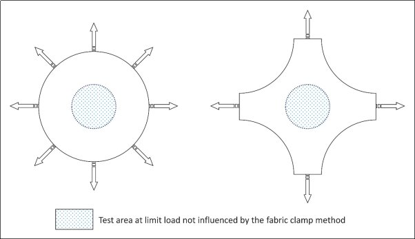
Examples of a circular or 2-directional test set-up
Pre-flight inspection requirements
The design of the envelope and pre-flight inspection method should be such that a damage length considerably smaller than the critical damage length will be discovered during a pre-flight inspection. The impact of aging and operating circumstances should be considered when establishing the margin between critical damage and detectable damage. (Refer to CS 31GB.27(g))
Design features that could possibly hinder discovery of damage during a pre-flight inspection should be avoided or taken into consideration when the detectable damage size is determined.
Note 1: It is assumed that an envelope damage exceeding 5 cm will be detected before flight due to the loss of gas.
Note 2: The critical damage is a design property that should not be confused with acceptable damage as provided in the flight manual.
ED Decision 2011/012/R
(a) Each control must operate easily, smoothly, and positively enough to allow proper performance of its functions. Controls must be so arranged and identified to prevent confusion and inadvertent operation.
(b) Each control system and operating device must be designed and installed in a manner that will prevent jamming, chafing, or unintended interference from passengers or loose items of equipment. The elements of the control system must have design features or must be distinctly and permanently marked to minimise the possibility of incorrect assembly that could result in malfunctioning of the control system.
(c) The envelope must be protected against bursting using a valve or appendix.
(d) There must be a valve to control the flight of the balloon. Proof of its reliable operation must be provided.
AMC 31GB.49(c) Control systems
ED Decision 2011/012/R
The envelope is protected against bursting when it is equipped with an appendix or valve that can automatically release gas at the rate of at least 3% of the total volume per minute at the balloon’s maximum operating pressure. The appendix or valve should be designed to prevent possible blockage during flight due to e.g. freezing, jamming or a reduction of the outflow opening due to deflection of the envelope and/or the outflow opening.
ED Decision 2011/012/R
(a) Disposable ballast must have means for safe storage and release. (See also CS 31GB.27(e))
(b) A minimum amount of ballast must be defined and reserved for the final landing which is sufficient (when jettisoned) to reduce the speed of descent to an acceptable value. The minimum ballast must be provided in the Flight Manual. (See CS 31GB.81(b)(2))
AMC 31GB.51 Disposable Ballast
ED Decision 2011/012/R
Ballast material should be easily transferred, disposed of and dissipated. Means need to be provided to prevent freezing and/or blocking the release of the ballast material. The material should not pollute the environment.
Dry sand is a well-proven material and is considered as suitable in the sense of this paragraph and this AMC.
The disposable ballast may be necessary for the pilot to perform the flight path management. The pre-take-off decision on the amount of disposable ballast should be left to the pilot as it is dependent on the flight task, the weather, etc.
A minimum ballast quantity is considered sufficient if, when jettisoned, it stops a descent speed of 4 m/s.
Note: The shape and drag of the envelope can have an effect on minimum descent speed, resulting in a minimum descent speed above 4 m/s.
ED Decision 2011/012/R
If a drag rope is used, the end that is released overboard must be stiffened to preclude the probability of the rope becoming entangled with trees, wires, or other objects on the ground.
CS 31GB.55 Rapid deflation means
ED Decision 2011/012/R
(a) The envelope must have means to allow for rapid deflation after landing. The system must be designed to minimise the possibility of inadvertent operation. If a system other than a manual system is used, the reliability of the system used must be substantiated.
(b) If a balloon is equipped with a lateral rapid deflation means, a device must be installed to align the balloon during landing in order to turn the rapid deflation means into its designated position.
AMC 31GB.55(a) Rapid deflation means
ED Decision 2011/012/R
A deflation is considered as ‘rapid’ if after a touchdown the balloon envelope is adequately prevented from ‘sailing’ and being dragged too much over the ground by the wind.
AMC 31GB.55(b) Rapid deflation means
ED Decision 2011/012/R
The installation of a drag rope is considered as a suitable device to align the balloon during landing in the sense of this subparagraph.
ED Decision 2011/012/R
(a) General
(1) All control cords used for flight control must be designed and installed to preclude entanglement.
(2) The function of control cords should be identified to the pilot and marked in accordance with paragraph (b), (c) and (d) if applicable.
(3) The maximum force required for their operation must not exceed 340 N.
(4) All control cords used for flight control must be long enough to allow for an increase of at least 10% in the vertical dimension of the envelope.
(b) Arming cords
If an arming device is employed to prevent inadvertent operation of an irreversible control, the part of the cord to be handled by the pilot must be coloured with yellow and black bands.
(c) Venting cords
(1) If a venting cord is used to allow controlled release of the lifting gas and the vent can be resealed in flight, the part of the cord to be handled by the pilot must be coloured with red and white bands.
(2) If a further cord is required to reseal any vent, the part of the cord handled by the pilot must be coloured white.
(d) Rapid or emergency deflation cords
(1) If a cord is used for rapid or emergency deflation of the envelope and the device cannot be resealed in flight, the part of the cord to be handled by the pilot must be coloured red.
(2) In addition to the force requirement of 31GB.57(a)(3) above, the force required to operate an emergency deflation cord must not be less than 110 N.
ED Decision 2011/012/R
(a) The basket may not rotate independently of the envelope unless:
(1) the rotation is under control of the pilot; and
(2) entanglement of operating lines is prevented.
(b) Each projecting object on the basket, that could cause injury to the occupants, must be padded.
(c) Occupants of a basket must be protected during hard or fast landings against:
(1) falling from the basket;
(2) serious injuries.
(d) When more than six occupants are carried, the basket must be divided into compartments, each containing not more than six occupants.
(e) Where basket proportions and compartmentation are such that more than one occupant may fall on top of another during landing, there must be means to minimise this possibility.
(f) Reasonable space must be provided for all occupants, with regard to both comfort during the flight and to safety during the landing.
(g) The space for the pilot must provide unobstructed operation in all flight phases.
(h) There must be hand holds for each occupant.
(i) Means must be provided to allow drainage of vapour or liquid from the bottom of the basket.
(j) The load-bearing parts (e.g. ropes or cables) of the suspension system must be protected against damage in normal service.
(k) The basket floor must not project beyond the sidewalls.
(l) Limitations on the occupancy and configuration of the basket must be provided in the Flight Manual. (See CS 31GB.81).
ED Decision 2011/012/R
The purpose of this subparagraph is to prevent entanglement of operating lines due to uncontrolled rotation.
It should be noted that uncontrolled rotation may also occur during landings with basket tip-over if the plan view of the basket floor is circular or more than hexagonal.
ED Decision 2011/012/R
An internal height of the basket of 1·10 m, protecting the occupants carried from falling from the basket, is considered compliant to this requirement.
ED Decision 2011/012/R
Alignment of the basket for landing using a drag rope or an equivalent feature and Flight Manual instructions specifying that the basket should be aligned to land on one of its longer sides can be used to show compliance to this requirement. No more than two occupants may be positioned in the landing direction without means to prevent them from falling on top of each other.
ED Decision 2011/012/R
Unless otherwise justified on safety grounds, a minimum figure of between 0·25 m² and 0·3 m² plan area should be used for each standing occupant, with proper account being taken of the specified size, number and position of equipment when applying this figure. There needs to be enough space provided for passengers to take a brace position for landing. The Agency should be consulted in cases where a basket’s shape or compartmentation makes the measurement of this figure subjective.
ED Decision 2011/012/R
Handholds need to be provided as an obvious means for the occupants to safely hold on to during a landing. The location or design of the handholds need to provide protection of the hands from impact during a landing.
ED Decision 2011/012/R
These limitations should state, for each permissible model of basket or other means provided for the occupants, the maximum permitted occupancy in relation to specified sizes, numbers and positions of equipment items.
CS 31GB.61 Electrostatic discharge
ED Decision 2011/012/R
There must be appropriate electrostatic discharge means in the design of each balloon whose lift-producing medium contains a flammable gas to ensure that the effects of electrostatic discharge will not create a hazard.
AMC 31GB.61 Electrostatic discharge
ED Decision 2011/012/R
Appropriate electrostatic discharge means are met when compliance with all of the following requirements is demonstrated.
(a) The surface resistance on the inside of the balloon envelope after 24-hour storage at a relative air humidity of less than 50% must be value 109 Ω or lower. The values are to be determined using approved measuring methods.
(b) The respective layer of a non-conductive material (surface resistance in excess of 109 Ω) must not be thicker than 0.3 mm unless it is enclosed by conductive layers.
(c) The balloon envelope and all other conductive parts of the balloon (surface resistance less than 109 Ω) must be conductively connected to each other (resistance of connection less than 106 Ω). This requirement also applies to the joints between the panels and reinforcements.
(d) There must be at least three independent discharge paths for the safe balance of the electrostatic charges from the inside of the envelope running to the bottom end of the basket.
(e) The discharge paths should run on the conductive side of the envelope from top to bottom and then further down to the ground. This requirement applies to the case when the balloon is in contact with earth’s surface.
(f) Each discharge path under (d) must be of different kind or design to the other.
(g) Periodic maintenance checks of the surface resistance and discharge paths should be included in the instructions for continued airworthiness.
Note: More detailed information can be found in:
EN 61340-5-1&2:2007 Protection of electronic devices from electrostatic phenomena – General Requirements & User guide
IEC 60093 Methods of Test for Volume Resistivity and Surface Resistivity of Solid Electrical Insulating Materials
ED Decision 2011/012/R
(a) There must be a restraining means for all occupants, which can take the form of hand holds. (See CS 31GB.59(h))
(b) For baskets having a separate pilot compartment, there must be a suitable restraint for the pilot which must meet the strength requirements of CS 31GB.30. Additionally, the restraint must be designed so that:
(1) the pilot can reach all the necessary controls when the restraint is correctly worn and adjusted;
(2) there is a method of quick release that is simple and obvious; and
(3) the possibility of inadvertent release is minimised.
ED Decision 2011/012/R
The pilot must be provided with an indication that any applicable limitations for tethered flight are being, or have been reached.
ED Decision 2011/012/R
The inclusion of an appropriate device or instrument (rated ‘weak link’, hand held anemometer, windsock, etc.) to provide the pilot with an attention-getting indication of the balloon’s tethering limitation, is considered compliant with CS 31GB.67.