ED Decision 2018/007/R
(a) Accessibility. Required safety equipment to be used by the crew in an emergency must be readily accessible.
(b) Stowage provisions. Stowage provisions for required safety equipment must be furnished and must:
(1) Be arranged so that the equipment is directly accessible and its location is obvious; and
(2) Protect the safety equipment from inadvertent damage.
(c) Emergency exit descent device. The stowage provisions for the emergency exit descent device required by CS 29.809(f) must be at the exits for which they are intended.
[Amdt No: 29/5]
AMC 29.1411 Safety equipment — General
ED Decision 2018/007/R
This AMC replaces FAA AC 29.1411.
(a) Explanation
CS-29 Amendment 5 introduced changes related to ditching and associated equipment. In particular, it defined a standard set of terminology, it simplified CS 29.1411 in line with it being a general certification specification for safety equipment, reorganised CS 29.1415 specifically for ditching equipment, and created a new CS 29.1470 on the installation and carriage of emergency locator transmitters (ELTs). All requirements relating to life raft installations are now co-located in CS 29.1415.
(1) The safety equipment should be accessible and appropriately stowed, and it should be ensured that:
(i) locations for stowage of all required safety equipment have been provided;
(ii) safety equipment is readily accessible to both crew members and passengers, as appropriate, during any reasonably probable emergency situation;
(iii) stowage locations for all required safety equipment will adequately protect such equipment from inadvertent damage during normal operations; and
(iv) safety equipment stowage provisions will protect the equipment from damage during emergency landings when subjected to the inertia loads specified in CS 29.561.
(b) Procedures
(1) A cockpit evaluation should be conducted to demonstrate that all required emergency equipment to be used by the flight crew will be readily accessible during any foreseeable emergency situation. This evaluation should include, for example, emergency flotation equipment actuation devices, remote life raft releases, door jettison handles, handheld fire extinguishers, and protective breathing equipment.
(2) Stowage provisions for safety equipment shown to be compatible with the vehicle configuration presented for certification should be provided and identified so that:
(i) equipment is readily accessible regardless of the operational configuration;
(ii) stowed equipment is free from inadvertent damage from passengers and handling; and
(iii) stowed equipment is adequately restrained to withstand the inertia forces specified in CS 29.561(b)(3) without sustaining damage.
(3) For rotorcraft required to have an emergency descent slide or rope according to CS 29.809(f), the stowage provisions for these devices should be located at the exits where those devices are intended to be used.
[Amdt No: 29/5]
CS 29.1413 Safety belts: passenger warning device
ED Decision 2003/16/RM
(a) If there are means to indicate to the passengers when safety belts should be fastened, they must be installed to be operated from either pilot seat.
(b) Each safety belt must be equipped with a metal to metal latching device.
ED Decision 2018/007/R
If certification with ditching provisions or emergency flotation provisions is requested by the applicant, the additional safety equipment required by any applicable operating rule must meet the requirements of this CS.
(a) All equipment must be approved.
(b) Life rafts.
(1) Required life raft(s) must be remotely deployable for use in an emergency. Remote controls capable of deploying the life raft(s) must be located within easy reach of the flight crew, occupants of the passenger cabin and survivors in the water, with the rotorcraft in the upright floating or capsized position. It must be substantiated that life raft(s) sufficient to accommodate all rotorcraft occupants, without exceeding the rated capacity of any life raft, can be reliably deployed with the rotorcraft in any reasonably foreseeable floating attitude, including capsized, and in the sea conditions chosen for demonstrating compliance with CS 29.801(e).
(2) Each life raft must have a short retaining line designed to hold the life raft near the rotorcraft and a long retaining line designed to keep the life raft attached to the rotorcraft. Both retaining lines must be designed to break before submerging the empty raft to which they are attached if the rotorcraft becomes totally submerged. The long retaining line must be of sufficient length that a drifting life raft will not be drawn towards any part of the rotorcraft that would pose a danger to the life raft itself or the persons on board.
(3) Each life raft must be substantiated as suitable for use in all sea conditions covered by the certification with ditching or emergency flotation provisions.
(4) The number of life rafts installed must be no less than two. The life rafts must be of an approximately equal rated capacity and buoyancy to accommodate all the occupants of the rotorcraft and unless excess life rafts of sufficient capacity are provided, the buoyancy and seating capacity beyond the rated capacity of each life raft (overload rating) must accommodate all occupants of the rotorcraft in the event of loss of one life raft of the largest rated capacity.
(c) Life preservers.
If the applicable operating rule allows for life preservers not to be worn at all times, stowage provisions must be provided that accommodate one life preserver for each occupant for which certification with ditching provisions is requested. A life preserver must be within easy reach of each occupant while seated.
(d) Survival equipment.
Approved survival equipment must be attached to each liferaft.
[Amdt No: 29/5]
AMC 29.1415 Ditching equipment
ED Decision 2018/007/R
This AMC replaces FAA AC 29.1415.
(a) Explanation
(1) Additional safety equipment is not required for all rotorcraft overwater operations. However, if such equipment is required by the applicable operating rule, the equipment supplied should satisfy this AMC.
NOTE: Although the term ‘ditching’ is most commonly associated with the design standards related to CS 29.801 (ditching approval), a rotorcraft equipped to the less demanding requirements of CS 29.802 (emergency flotation approval), when performing an emergency landing on to water, would nevertheless be commonly described as carrying out the process of ditching. The term ‘ditching equipment’ is therefore to be considered to apply to any safety equipment required by operational rule for operation over water.
It is a frequent practice for the rotorcraft manufacturer to provide the substantiation for only those portions of the ditching requirements relating to rotorcraft flotation and emergency exits. Completion of the ditching certification to include the safety equipment installation and stowage provisions is then left to the affected operator so that those aspects can best be adapted to the selected cabin interior. In such cases, the ‘Limitations’ section of the rotorcraft flight manual (RFM) should identify the substantiations yet to be provided in order to justify the full certification with ditching provisions. The modifier performing these final installations is then concerned directly with the details of this AMC. Any issues arising from aspects of the basic rotorcraft flotation and emergency exits certification that are not compatible with the modifier’s proposed safety equipment provisions should be resolved between the type certificate (TC) holder and the modifier prior to the certifying authority’s certification with ditching provisions (see AMC 29.801(b)(13) and AMC 29.1415(a)(2)(ii)).
(2) Compliance with the requirements of CS 29.801 for rotorcraft ditching requires compliance with the safety equipment stowage requirements and ditching equipment requirements of CS 29.1411 and CS 29.1415, respectively.
(i) Ditching equipment installed to complete ditching certification, or required by the applicable operating rule, should be compatible with the basic rotorcraft configuration presented for ditching certification. It is satisfactory if the ditching equipment is not incorporated at the time of the original rotorcraft type certification provided that suitable information is included in the ‘Limitations’ section of the rotorcraft flight manual (RFM) to identify the extent of ditching certification not yet completed.
(ii) When ditching equipment is being installed by a person other than the applicant who provided the rotorcraft flotation system and emergency exits, special care should be taken to avoid degrading the functioning of those items, and to make the ditching equipment compatible with them (see AMC 29.801(b)(13)).
(b) Procedures
All ditching equipment, including life rafts, life preservers, immersion suits, emergency breathing systems etc., should be of an approved type. Life rafts should be chosen to be suitable for use in all sea conditions covered by the certification with ditching provisions.
(1) Life rafts
(i) Life rafts are rated during their certification according to the number of people that can be carried under normal conditions and the number that can be accommodated in an overload condition. Only the normal rating may be used in relation to the number of occupants permitted to fly in the rotorcraft.
(ii) The life rafts should deploy on opposite sides of the rotorcraft in order to minimise the probability that all may be damaged during water entry/impact, and to provide the maximum likelihood that at least half of those provided will be useable in any wind condition.
(iii) Successful deployment of life raft installations should be demonstrated in all representative conditions. Testing should be performed, including underwater deployment, if applicable, to demonstrate that life rafts sufficient to accommodate all rotorcraft occupants, without exceeding the rated capacity of any life raft, will deploy reliably with the rotorcraft in any reasonably foreseeable floating attitude, including capsized. It should also be substantiated that reliable deployment will not be compromised by inertial effects from the rolling/pitching/heaving of the rotorcraft in the sea conditions chosen for the demonstration of compliance with the flotation/trim requirements of CS 29.801(e), or by intermittent submerging of the stowed raft location (if applicable) and the effects of wind. This substantiation should also consider all reasonably foreseeable rotorcraft floating attitudes, including capsized. Reasonably foreseeable floating attitudes are considered to be, as a minimum, upright, with and without loss of the critical emergency flotation system (EFS) compartment, and capsized, also with and without loss of the critical EFS compartment. Consideration should also be given towards maximising, where practicable, the likelihood of life raft deployment for other cases of EFS damage.
(iv) Rotorcraft fuselage attachments for the life raft retaining lines should be provided.
(A) Each life raft should be equipped with two retaining lines to be used for securing the life raft to the rotorcraft. The short retaining line should be of such a length as to hold the raft at a point next to an upright floating rotorcraft such that the occupants can enter the life raft directly without entering the water. If the design of the rotorcraft is such that the flight crew cannot enter the passenger cabin, it is acceptable that they would need to take a more indirect route when boarding the life raft. After life raft boarding is completed, the short retaining line may be cut and the life raft then remain attached to the rotorcraft by means of the long retaining line.
(B) Attachments on the rotorcraft for the retaining lines should not be susceptible to damage when the rotorcraft is subjected to the maximum water entry loads established by CS 29.563.
(C) Attachments on the rotorcraft for the retaining lines should be structurally adequate to restrain a fully loaded life raft.
(D) Life rafts should be attached to the rotorcraft by the required retaining lines after deployment without further action from the crew or passengers.
(E) It should be verified that the length of the long retaining line will not result in the life raft taking up a position which could create a potential puncture risk or hazard to the occupants, such as directly under the tail boom, tail rotor or main rotor disc.
(v) Life raft stowage provisions should be sufficient to accommodate rafts for the maximum number of occupants for which certification for ditching is requested by the applicant.
(vi) Life raft activation
The following should be provided for each life raft:
(A) primary activation: manual activation control(s), readily accessible to each pilot on the flight deck whilst seated;
(B) secondary activation: activation control(s) accessible from the passenger cabin with the rotorcraft in the upright or capsized position; if any control is located within the cabin, it should be protected from inadvertent operation; and
(C) tertiary activation: activation control(s) accessible to a person in the water, with the rotorcraft in any foreseeable floating attitude, including capsized.
It is acceptable for two of these manual activation functions to be incorporated into one control.
Automatic life raft activation is not prohibited (e.g. it could be triggered by water immersion). However, such a capability should be provided in addition to the above manual activation controls, not instead of them, and issues such as inadvertent deployment in flight and the potential for damage from turning rotors during deployment on the water should be mitigated.
Placards should be installed, of appropriate size, number and location, to highlight the location of each of the above life raft activation controls. All reasonably foreseeable rotorcraft floating attitudes should be considered.
(vii) Protection of life rafts from damage
Service experience has shown that following deployment, life rafts are susceptible to damage while in the water adjacent to the rotorcraft due to projections on the exterior of the rotorcraft such as antennas, overboard vents, unprotected split pin tails, guttering, etc. and any projections sharper than a three dimensional right angled corner. Projections likely to cause damage to a deployed life raft should be avoided by design, or suitably protected to minimise the likelihood of their causing damage to a deployed life raft. In general, projections on the exterior surface of the helicopter, that are located in a zone delineated by boundaries that are 1.22 m (4 ft) above and 0.61 m (2 ft) below the established static water line should be assessed. Relevant maintenance information should also provide procedures for maintaining such protection for rotorcraft equipped with life rafts. Furthermore, due account should be taken of the likely damage that may occur (e.g. disintegration of carbon-fibre panels or structure) during water entry and its potential hazard to deployed life rafts.
(2) Life preservers.
No provision for the stowage of life preservers is necessary if the applicable operating rule mandates the need for constant-wear life preservers.
(3) Emergency signalling equipment
Emergency signalling equipment required by the applicable operating rule should be free from hazards in its operation, and operable using either bare or gloved hands. Required signalling equipment should be easily accessible to the passengers or crew and located near a ditching emergency exit or included in the survival equipment attached to the life rafts.
[Amdt No: 29/5]
ED Decision 2003/16/RM
(a) To obtain certification for flight into icing conditions, compliance with this paragraph must be shown.
(b) It must be demonstrated that the rotorcraft can be safely operated in the continuous maximum and intermittent maximum icing conditions determined under Appendix C within the rotorcraft altitude envelope. An analysis must be performed to establish, on the basis of the rotorcraft’s operational needs, the adequacy of the ice protection system for the various components of the rotorcraft.
(c) In addition to the analysis and physical evaluation prescribed in sub-paragraph (b), the effectiveness of the ice protection system and its components must be shown by flight tests of the rotorcraft or its components in measured natural atmospheric icing conditions and by one or more of the following tests as found necessary to determine the adequacy of the ice protection system:
(1) Laboratory dry air or simulated icing tests, or a combination of both, of the components or models of the components.
(2) Flight dry air tests of the ice protection system as a whole, or its individual components.
(3) Flight tests of the rotorcraft or its components in measured simulated icing conditions.
(d) The ice protection provisions of this paragraph are considered to be applicable primarily to the airframe. Powerplant installation requirements are contained in Subpart E of this CS-29.
(e) A means must be identified or provided for determining the formation of ice on critical parts of the rotorcraft. Unless otherwise restricted, the means must be available for night- time as well as daytime operation. The rotorcraft flight manual must describe the means of determining ice formation and must contain information necessary for safe operation of the rotorcraft in icing conditions.
Appendix C – Icing Certification
ED Decision 2003/16/RM
(a) The maximum continuous intensity of atmospheric icing conditions (continuous maximum icing) is defined by the variables of the cloud liquid water content, the mean effective diameter of the cloud droplets, the ambient air temperature, and the interrelationship of these three variables as shown in figure 1 of this appendix. The limiting icing envelope in terms of altitude and temperature is given in figure 2 of this appendix. The interrelationship of cloud liquid water content with drop diameter and altitude is determined from figures 1 and 2. The cloud liquid water content for continuous maximum icing conditions of a horizontal extent, other than 32.2 km (17.4 nautical miles), is determined by the value of liquid water content of figure 1, multiplied by the appropriate factor from figure 3 of this appendix.
(b) The intermittent maximum intensity of atmospheric icing conditions (intermittent maximum icing) is defined by the variables of the cloud liquid water content, the mean effective diameter of the cloud droplets, the ambient air temperature, and the interrelationship of these three variables as shown in figure 4 of this appendix. The limiting icing envelope in terms of altitude and temperature is given in figure 5 of this appendix. The interrelationship of cloud liquid water content with drop diameter and altitude is determined from figures 4 and 5. The cloud liquid water content for intermittent maximum icing conditions of a horizontal extent, other than 4.8 km (2.6 nautical miles), is determined by the value of cloud liquid water content of figure 4 multiplied by the appropriate factor in figure 6 of this appendix.
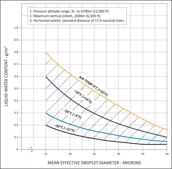
FIGURE 1
CONTINUOUS MAXIMUM (STRATIFORM CLOUDS) ATMOSPHERIC ICING CONDITIONS
LIQUID WATER CONTENT VS MEAN EFFECTIVE DROP DIAMETER
Source of data – NACA TN No. 1855, Class III - M, Continuous Maximum.
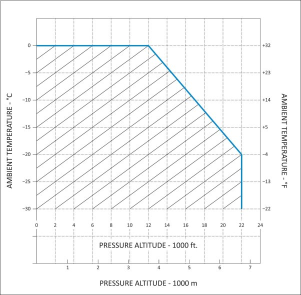
FIGURE 2
CONTINUOUS MAXIMUM (STRATIFORM CLOUDS) ATMOSPHERIC ICING CONDITIONS
AMBIENT TEMPERATURE VS PRESSURE ALTITUDE
Source of data – NACA TN No. 2569.
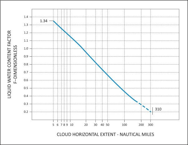
FIGURE 3
CONTINUOUS MAXIMUM (STRATIFORM CLOUDS) ATMOSPHERIC ICING CONDITIONS
LIQUID WATER CONTENT FACTOR VS CLOUD HORIZONTAL DISTANCE
Source of data – NACA TN No. 2738.

FIGURE 4
INTERMITTENT MAXIMUM (CUMULIFORM CLOUDS) ATMOSPHERIC ICING CONDITIONS
LIQUID WATER CONTENT VS MEAN EFFECTIVE DROP DIAMETER
Source of data – NACA TN No. 1855, Class II - M, Intermittent Maximum.
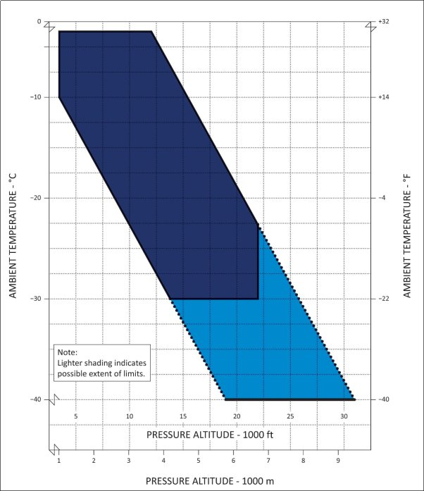
FIGURE 5
INTERMITTENT MAXIMUM (CUMULIFORM CLOUDS) ATMOSPHERIC ICING CONDITIONS
AMBIENT TEMPERATURE VS PRESSURE ALTITUDE
Source of data – NACA TN No. 2569.
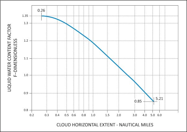
FIGURE 6
INTERMITTENT MAXIMUM (CUMULIFORM CLOUDS) ATMOSPHERIC ICING CONDITIONS
VARIATION OF LIQUID WATER CONTENT FACTOR WITH CLOUD HORIZONTAL EXTENT
Source of data – NACA TN No. 2738.