ED Decision 2003/16/RM
For each pilot compartment:
(a) The compartment and its equipment must allow each pilot to perform his duties without unreasonable concentration or fatigue;
(b) If there is provision for a second pilot, the rotorcraft must be controllable with equal safety from either pilot position. Flight and powerplant controls must be designed to prevent confusion or inadvertent operation when the rotorcraft is piloted from either position;
(c) The vibration and noise characteristics of cockpit appurtenances may not interfere with safe operation;
(d) Inflight leakage of rain or snow that could distract the crew or harm the structure must be prevented.
CS 29.773 Pilot compartment view
ED Decision 2003/16/RM
(a) Non precipitation conditions. For non precipitation conditions, the following apply:
(1) Each pilot compartment must be arranged to give the pilots a sufficiently extensive, clear, and undistorted view for safe operation.
(2) Each pilot compartment must be free of glare and reflection that could interfere with the pilot’s view. If certification for night operation is requested, this must be shown by night flight tests.
(b) Precipitation conditions. For precipitation conditions, the following apply:
(1) Each pilot must have a sufficiently extensive view for safe operation:
(i) In heavy rain at forward speeds up to VH; and
(ii) In the most severe icing condition for which certification is requested.
(2) The first pilot must have a window that:
(i) Is openable under the conditions prescribed in sub-paragraph (b)(1); and
(ii) Provides the view prescribed in that paragraph.
CS 29.775 Windshields and windows
ED Decision 2003/16/RM
Windshields and windows must be made of material that will not break into dangerous fragments.
ED Decision 2003/16/RM
Cockpit controls must be:
(a) Located to provide convenient operation and to prevent confusion and inadvertent operation; and
(b) Located and arranged with respect to the pilot’s seats so that there is full and unrestricted movement of each control without interference from the cockpit structure or the pilot’s clothing when pilots from 1.57 m (5ft 2ins) to 1.8 m (6ft) in height are seated.
CS 29.779 Motion and effect of cockpit controls
ED Decision 2003/16/RM
Cockpit controls must be designed so that they operate in accordance with the following movements and actuation:
(a) Flight controls, including the collective pitch control, must operate with a sense of motion which corresponds to the effect on the rotorcraft.
(b) Twist-grip engine power controls must be designed so that, for left-hand operation, the motion of the pilot’s hand is clockwise to increase power when the hand is viewed from the edge containing the index finger. Other engine power controls, excluding the collective control, must operate with a forward motion to increase power.
(c) Normal landing gear controls must operate downward to extend the landing gear.
ED Decision 2018/007/R
(a) Each closed cabin must have at least one adequate and easily accessible external door.
(b) Each external door must be located, and appropriate operating procedures must be established, to ensure that persons using the door will not be endangered by the rotors, propellers, engine intakes, and exhausts when the operating procedures are used.
(c) There must be means for locking crew and external passenger doors and for preventing their opening in flight inadvertently or as a result of mechanical failure. It must be possible to open external doors from inside and outside the cabin with the rotorcraft on the ground even though persons may be crowded against the door on the inside of the rotorcraft. The means of opening must be simple and obvious and so arranged and marked that it can be readily located and operated.
(d) There must be reasonable provisions to prevent the jamming of any external door in a minor crash as a result of fuselage deformation under the following ultimate inertial forces except for cargo or service doors not suitable for use as an exit in an emergency:
(1) Upward – 1.5 g
(2) Forward – 4.0 g
(3) Sideward – 2.0 g
(4) Downward – 4.0 g
(e) There must be means for direct visual inspection of the locking mechanism by crew members to determine whether the external doors (including passenger, crew, service, and cargo doors) are fully locked. There must be visual means to signal to appropriate crew members when normally used external doors are closed and fully locked.
(f) For outward opening external doors usable for entrance or egress, there must be an auxiliary safety latching device to prevent the door from opening when the primary latching mechanism fails. If the door does not meet the requirements of sub-paragraph (c) with this device in place, suitable operating procedures must be established to prevent the use of the device during take-off and landing.
(g) If an integral stair is installed in a passenger entry door that is qualified as a passenger emergency exit, the stair must be designed so that under the following conditions the effectiveness of passenger emergency egress will not be impaired:
(1) The door, integral stair, and operating mechanism have been subjected to the inertial forces specified in sub-paragraph (d), acting separately relative to the surrounding structure.
(2) The rotorcraft is in the normal ground attitude and in each of the attitudes corresponding to collapse of one or more legs, or primary members, as applicable, of the landing gear.
(h) Non jettisonable doors used as ditching emergency exits must have means to enable them to be secured in the open position and remain secure for emergency egress in all sea conditions for which ditching capability is requested by the applicant.
[Amdt No: 29/5]
CS 29.785 Seats, berths, safety belts, and harnesses
ED Decision 2003/16/RM
(a) Each seat, safety belt, harness, and adjacent part of the rotorcraft at each station designated for occupancy during take-off and landing must be free of potentially injurious objects, sharp edges, protuberances, and hard surfaces and must be designed so that a person making proper use of these facilities will not suffer serious injury in an emergency landing as a result of the inertial factors specified in CS 29.561(b) and dynamic conditions specified in CS 29.562.
(b) Each occupant must be protected from serious head injury by a safety belt plus a shoulder harness that will prevent the head from contacting any injurious object except as provided for in CS 29.562(c)(5). A shoulder harness (upper torso restraint), in combination with the safety belt, constitutes a torso restraint system as described in ETSO-C114.
(c) Each occupant’s seat must have a combined safety belt and shoulder harness with a single-point release. Each pilot’s combined safety belt and shoulder harness must allow each pilot when seated with safety belt and shoulder harness fastened to perform all functions necessary for flight operations. There must be a means to secure belts and harnesses, when not in use, to prevent interference with the operation of the rotorcraft and with rapid egress in an emergency.
(d) If seat backs do not have a firm handhold, there must be hand grips or rails along each aisle to let the occupants steady themselves while using the aisle in moderately rough air.
(e) Each projecting object that would injure persons seated or moving about in the rotorcraft in normal flight must be padded.
(f) Each seat and its supporting structure must be designed for an occupant weight of at least 77 kg (170 pounds) considering the maximum load factors, inertial forces, and reactions between the occupant, seat, and safety belt or harness corresponding with the applicable flight and ground load conditions, including the emergency landing conditions of CS 29.561(b). In addition:
(1) Each pilot seat must be designed for the reactions resulting from the application of the pilot forces prescribed in CS 29.397; and
(2) The inertial forces prescribed in CS 29.561(b) must be multiplied by a factor of 1.33 in determining the strength of the attachment of:
(i) Each seat to the structure; and
(ii) Each safety belt or harness to the seat or structure.
(g) When the safety belt and shoulder harness are combined, the rated strength of the safety belt and shoulder harness may not be less than that corresponding to the inertial forces specified in CS 29.561(b), considering the occupant weight of at least 77 kg (170 pounds), considering the dimensional characteristics of the restraint system installation, and using a distribution of at least a 60% load to the safety belt and at least a 40% load to the shoulder harness. If the safety belt is capable of being used without the shoulder harness, the inertial forces specified must be met by the safety belt alone.
(h) When a headrest is used, the headrest and its supporting structure must be designed to resist the inertia forces specified in CS 29.561, with a 1.33 fitting factor and a head weight of at least 5.9 kg (13 pounds).
(i) Each seating device system includes the device such as the seat, the cushions, the occupant restraint system, and attachment devices.
(j) Each seating device system may use design features such as crushing or separation of certain parts of the seat in the design to reduce occupant loads for the emergency landing dynamic conditions of CS 29.562; otherwise, the system must remain intact and must not interfere with rapid evacuation of the rotorcraft.
(k) For the purposes of this paragraph, a litter is defined as a device designed to carry a non ambulatory person, primarily in a recumbent position, into and on the rotorcraft. Each berth or litter must be designed to withstand the load reaction of an occupant weight of at least 77 kg (170 pounds) when the occupant is subjected to the forward inertial factors specified in CS 29.561(b). A berth or litter installed within 15° or less of the longitudinal axis of the rotorcraft must be provided with a padded end- board, cloth diaphragm, or equivalent means that can withstand the forward load reaction. A berth or litter oriented greater than 15° with the longitudinal axis of the rotorcraft must be equipped with appropriate restraints, such as straps or safety belts, to withstand the forward reaction. In addition:
(1) The berth or litter must have a restraint system and must not have corners or other protuberances likely to cause serious injury to a person occupying it during emergency landing conditions; and
(2) The berth or litter attachment and the occupant restraint system attachments to the structure must be designed to withstand the critical loads resulting from flight and ground load conditions and from the conditions prescribed in CS 29.561(b). The fitting factor required by CS 29.625(d) shall be applied.
CS 29.787 Cargo and baggage compartments
ED Decision 2003/16/RM
(a) Each cargo and baggage compartment must be designed for its placarded maximum weight of contents and for the critical load distributions at the appropriate maximum load factors corresponding to the specified flight and ground load conditions, except the emergency landing conditions of CS 29.561.
(b) There must be means to prevent the contents of any compartment from becoming a hazard by shifting under the loads specified in subparagraph (a).
(c) Under the emergency landing conditions of CS 29.561, cargo and baggage compartments must:
(1) Be positioned so that if the contents break loose they are unlikely to cause injury to the occupants or restrict any of the escape facilities provided for use after an emergency landing; or
(2) Have sufficient strength to withstand the conditions specified in CS 29.561, including the means of restraint and their attachments required by sub-paragraph (b). Sufficient strength must be provided for the maximum authorised weight of cargo and baggage at the critical loading distribution.
(d) If cargo compartment lamps are installed, each lamp must be installed so as to prevent contact between lamp bulb and cargo.
ED Decision 2018/007/R
(a) If certification with ditching provisions is requested by the applicant, the rotorcraft must meet the requirements of this CS and CS 29.563, CS 29.783(h), CS 29.803(c), CS 29.805(c), CS 29.807(d), CS 29.809(j), CS 29.811(h), CS 29.813(d), CS 29.1411, CS 29.1415, CS 29.1470, CS 29.1555(d)(3) and CS 29.1561.
(b) Each practicable design measure, compatible with the general characteristics of the rotorcraft, must be taken to minimise the probability that when ditching, the behaviour of the rotorcraft would cause immediate injury to the occupants or would make it impossible for them to escape.
(c) An emergency flotation system that is stowed in a deflated condition during normal flight must:
(1) be designed such that the effects of a water impact (i.e. crash) on the emergency flotation system are minimised.
(2) have a means of automatic deployment following water entry. Automatic deployment must not rely on any pilot action during flight.
(d) The probable behaviour of the rotorcraft during ditching water entry must be must be shown to exhibit no unsafe characteristics.
(e) The rotorcraft must be shown to resist capsize in the sea conditions selected by the applicant. The probability of capsizing in a 5-minute exposure to the sea conditions must be substantiated to be less than or equal to 3.0 % with a fully serviceable emergency flotation system and 30.0 % with the critical float compartment failed, with 95 % confidence.
Allowances must be made for probable structural damage and leakage.
(f) Unless the effects of the collapse of external doors and windows are accounted for in the investigation of the probable behaviour of the rotorcraft during ditching (as prescribed in sub-paragraphs (d) and (e)), the external doors and windows must be designed to withstand the probable maximum local pressures.
(g) It must be shown that the rotorcraft will not sink following the functional loss of any single complete flotation unit.
[Amdt No: 29/5]
ED Decision 2018/007/R
This AMC replaces FAA AC 29.801.
(a) Definitions
(1) Ditching: a controlled emergency landing on the water, deliberately executed in accordance with rotorcraft flight manual (RFM) procedures, with the intent of abandoning the rotorcraft as soon as practicable.
(2) Emergency flotation system (EFS): a system of floats and any associated parts (e.g. gas cylinders, means of deployment, pipework and electrical connections) that is designed and installed on a rotorcraft to provide buoyancy and flotation stability in a ditching.
(b) Explanation
(1) Ditching certification is performed only if requested by the applicant.
(2) For a rotorcraft to be certified for ditching, in addition to the other applicable requirements of CS-29, the rotorcraft must specifically meet CS 29.801 together with the requirements referenced in CS 29.801(a).
(3) Ditching certification encompasses four primary areas of concern: rotorcraft water entry and flotation stability (including loads and flotation system design), occupant egress, and occupant survival. CS-29 Amendment 5 has developed enhanced standards in all of these areas.
(4) The scope of the ditching requirements is expanded at Amendment 5 through a change in the ditching definition. All potential failure conditions that could result in a controlled ‘land immediately’ action by the pilot are now included. This primarily relates to changes in water entry conditions. While the limiting conditions for water entry have been retained (15.4 m/s, 1.5 m/s), the alleviation that previously allowed less than 15.4 m/s (30 kt) forward speed to be substantiated as the maximum applicable value has been removed (also from CS 29.563).
(5) Flotation stability is enhanced through the introduction of a new standard based on a probabilistic approach to capsizes.
(6) Failure of the EFS to operate when required will lead to the rotorcraft rapidly capsizing and sinking. Operational experience has shown that localised damage or failure of a single component of an EFS, or the failure of the flight crew to activate or deploy the EFS, can lead to the loss of the complete system. Therefore, the design of the EFS needs careful consideration; automatic arming and deployment have been shown to be practicable and to offer a significant safety benefit.
(7) The sea conditions, on which certification with ditching provisions is to be based, are selected by the applicant and should take into account the expected sea conditions in the intended areas of operation. The wave climate of the northern North Sea is adopted as the default wave climate as it represents a conservative condition. The applicant may also select alternative/additional sea areas with any associated certification then being limited to those geographical regions. The significant wave height, and any geographical limitations (if applicable – see the AMC to CS 29.801(e) and 29.802(c)) should be included in the RFM as performance information.
(8) During scale model testing, appropriate allowances should be made for probable structural damage and leakage. Previous model tests and other data from rotorcraft of similar configurations that have already been substantiated based on equivalent test conditions may be used to satisfy the ditching requirements. In regard to flotation stability, the test conditions should be equivalent to those defined in AMC to 29.801(e) and 29.802(c).
(9) CS 29.801(e) requires that after ditching in sea conditions for which certification with ditching provisions is requested by the applicant, the probability of capsizing in a 5 minute exposure is acceptably low in order to allow the occupants to leave the rotorcraft and enter life rafts. This should be interpreted to mean that up to and including the worst-case sea conditions for which certification with ditching provisions is requested by the applicant, the probability that the rotorcraft will capsize should be not higher than the target stated in the certification specification. An acceptable means of demonstrating post-ditching flotation stability is through scale model testing using irregular waves. The AMC to CS 29.801(e) and 29.802(c) contains a test specification that has been developed for this purpose.
(10) Providing a ‘wet floor’ concept (water in the cabin) by positioning the floats higher on the fuselage sides and allowing the rotorcraft to float lower in the water, can be a way of increasing the stability of a ditched rotorcraft (although this would need to be verified for the individual rotorcraft type for all weight and loading conditions), or it may be desirable for other reasons. This is permissible provided that the mean static level of water in the cabin is limited to being lower than the upper surface of the seat cushion (for all rotorcraft mass and centre of gravity cases, with all flotation units intact), and that the presence of water will not unduly restrict the ability of occupants to evacuate the rotorcraft and enter the life raft.
(11) It should be shown by analysis or other means that the rotorcraft will not sink following the functional loss of any single complete ditching flotation unit. Experience has shown that in water impact events, the forces exerted on the emergency flotation unit that first comes into contact with the water surface, together with structural deformation and other damage, can render the unit unusable. Maintenance errors may also lead to a flotation unit failing to inflate. The ability of occupants to egress successfully is significantly increased if the rotorcraft does not sink. However, this requirement is not intended for any other purpose, such as aiding salvage of the rotorcraft. Therefore, consideration of the remaining flotation units remaining inflated for an especially long period, i.e. longer than required in the upright floating case, is not required.
(12) The sea conditions approved for ditching should be stated in the performance information section of the RFM.
(13) Current practices allow wide latitude in the design of cabin interiors and, consequently, of stowage provisions for safety and ditching equipment. Rotorcraft manufacturers may deliver aircraft with unfinished (green) interiors that are to be completed by a modifier.
(i) Segmented certification is permitted to accommodate this practice. That is, the rotorcraft manufacturer shows compliance with the flotation time, stability, and emergency exit requirements while a modifier shows compliance with the equipment and egress requirements with the interior completed. This procedure requires close cooperation and coordination between the manufacturer, modifier, and EASA.
(ii) The rotorcraft manufacturer may elect to establish a token interior for ditching certification. This interior may subsequently be modified by a supplemental type certificate (STC). The ditching provisions should be shown to be compliant with the applicable requirements after any interior configuration or limitation change.
(iii) The RFM and any RFM supplements deserve special attention if a segmented certification procedure is pursued.
(c) Procedures
(1) Flotation system design
(i) Structural integrity should be established in accordance with CS 29.563.
(ii) Rotorcraft handling qualities should be verified to comply with the applicable certification specifications throughout the approved flight envelope with floats installed. Where floats are normally deflated, and deployed in flight, the handling qualities should be verified for the approved operating envelopes with the floats in:
(A) the deflated and stowed condition;
(B) the fully inflated condition; and
(C) the in-flight inflation condition; for float systems which may be inflated in flight, rotorcraft controllability should be verified by test or analysis, taking into account all possible emergency flotation system inflation failures.
(iii) Reliability should be considered in the basic design to assure approximately equal inflation of the floats to preclude excessive yaw, roll, or pitch in flight or in the water:
(A) Maintenance procedures should not degrade the flotation system (e.g. by introducing contaminants that could affect normal operation, etc.).
(B) The flotation system design should preclude inadvertent damage due to normal personnel traffic flow and wear and tear. Protection covers should be evaluated for function and reliability.
(C) The designs of the floats should provide means to minimise the likelihood of damage or tear propagation between compartments. Single compartment float designs should be avoided.
(D) When showing compliance with CS 29.801(c)(1), and where practicable, the design of the flotation system should consider the likely effects of water impact (i.e. crash) loads. For example:
(a) locate system components away from the major effects of structural deformation;
(b) use redundant or distributed systems;
(c) use flexible pipes/hoses; and
(d) avoid passing pipes/hoses or electrical wires through bulkheads that could act as a ‘guillotine’ when the structure is subject to water impact loads.
(iv) The floats should be fabricated from highly conspicuous material to assist in the location of the rotorcraft following a ditching (and possible capsize).
(2) Flotation system inflation.
Emergency flotation systems (EFSs) that are normally stowed in a deflated condition and are inflated either in flight or after contact with water should be evaluated as follows:
(i) The emergency flotation system should include a means to verify its system integrity prior to each flight.
(ii) Means should be provided to automatically trigger the inflation of the EFS upon water entry, irrespective of whether or not inflation prior to water entry is the intended operation mode. If a manual means of inflation is provided, the float activation switch should be located on one of the primary flight controls and should be safeguarded against inadvertent actuation.
(iii) The inflation system should be shown to have an appropriately low probability of spontaneous or inadvertent actuation in flight conditions for which float deployment has not been demonstrated to be safe. If this is achieved by disarming of the inflation system, this should be achieved by the use of an automatic system employing appropriate input parameters. The choice of input parameters, and architecture of the system, should such that rearming of the system occurs automatically in a manner that will assure the inflation system functions as intended in the event of a water impact. As required by CS 29.801(c), in achieving this, it is not acceptable to specify any pilot action during flight. Float disarming is typically required at high airspeeds, and could be achieved automatically using an airspeed switch. However, this would retain the possibility of inadvertent flight into the water at high airspeed, with the risk that the floats would not deploy. This scenario could be addressed by providing an additional or alternative means of rearming the floats as the aircraft descends through an appropriate height threshold. A height below that of the majority of offshore helidecks could be chosen in order to minimise exposure to inadvertent activation above the demonstrated float deployment airspeed.
(iv) The maximum airspeeds for intentional in-flight actuation of the emergency flotation system and for flight with the floats inflated should be established as limitations in the RFM unless in-flight actuation is prohibited by the RFM.
(v) Activation of the emergency flotation system upon water entry (irrespective of whether or not inflation prior to water entry is the intended operation mode) should result in an inflation time short enough to prevent the rotorcraft from becoming excessively submerged.
(vi) A means should be provided for checking the pressure of the gas storage cylinders prior to take-off. A table of acceptable gas cylinder pressure variation with ambient temperature and altitude (if applicable) should be provided.
(vii) A means should be provided to minimise the possibility of over inflation of the flotation units under any reasonably probable actuation conditions.
(viii) The ability of the floats to inflate without puncturing when subjected to actual water pressures should be substantiated. A demonstration of a full-scale float immersion in a calm body of water is one acceptable method of substantiation. Precautions should also be taken to avoid floats being punctured due to the proximity of sharp objects, during inflation in flight and with the helicopter in the water, and during subsequent movement of the helicopter in waves. Examples of objects that need to be considered are aerials, probes, overboard vents, unprotected split-pin tails, guttering and any projections sharper than a three-dimensional right-angled corner.
(ix) The inflation system design should, where practicable, minimise the possibility of foreseeable damage preventing the operation or partial operation of the EFS (e.g. interruption of the electrical supply or pipework). This could be achieved through the use of redundant systems or through distributed systems where each flotation unit is capable of autonomous operation (i.e. through the provision of individual inflation gas sources, electrical power sources and float activation switches).
(x) The inflation system design should minimise the probability that the floats do not inflate properly or inflate asymmetrically in the event of a ditching. This may be accomplished by interconnecting inflation gas sources, for which flexible hoses should be used to minimise potential damage, or by synchronising the deployment of autonomous flotation units. Note that the main concern in the event of a water impact is to prevent the rotorcraft from sinking; asymmetric deployment is a lesser concern.
(xi) CS 29.801(g) requires it to be shown that the rotorcraft will not sink following the functional loss of any complete flotation unit. A ’complete flotation unit’ shall be taken to mean a discrete, independently located float. The qualifying term ‘complete’ means that the entire structure of the flotation unit must be considered, not limited to any segregated compartments.
The loss of function of a flotation unit is most likely to be due to damage occurring in a water impact. However, there may be other reasons, such as undetected damage during maintenance, or incorrect maintenance. All reasonably probable causes for the loss of functionality of a flotation unit, and the resultant effect(s) on the remainder of the inflation system, should therefore be taken into account.
In the case of inflatable flotation units, irrespective of whether the intended operation is to deploy the system before or after water entry, the following shall be taken into account when assessing the ability of the rotorcraft to remain afloat;
— Following the functional loss of a deployed flotation unit, the capability to maintain pressure in the remaining inflation units should be justified on the basis of the inflation system design, for example:
— Individual inflation gas sources per flotation unit,
— Installation of non-return valves at appropriate locations.
— Following the functional loss of a non-deployed flotation unit, the capability of the remaining flotation units to deploy should be justified on the basis of the inflation system design, for example:
— The functionality of the inflation gas sources integrated with the functionally lost flotation unit in question should also either be assumed to be lost, or justification should otherwise be provided,
— The degree of inflation of the remaining undamaged flotation units, which share parts of the inflation system with the damaged unit, bearing in mind that the damaged unit will be venting, should be determined.
(3) Injury prevention during and following water entry.
An assessment of the cabin and cockpit layouts should be undertaken to minimise the potential for injury to occupants in a ditching. This may be performed as part of the compliance with CS 29.785. Attention should be given to the avoidance of injuries due to arm/leg flailing, as these can be a significant impediment to occupant egress and subsequent survivability. Practical steps that could be taken include:
(i) locating potentially hazardous equipment away from the occupants;
(ii) installing energy-absorbing padding onto interior components;
(iii) using frangible materials; and
(iv) designs that exclude hard or sharp edges.
(4) Water entry procedures.
Tests or simulations (or a combination of both) should be conducted to establish procedures and techniques to be used for water entry, based on the conditions given in (5). These tests/simulations should include determination of the optimum pitch attitude and forward velocity for ditching in a calm sea as well as entry procedures for the most severe sea condition to be certified. Procedures for all failure conditions that may lead to a ‘land immediately’ action (e.g. one engine inoperative, all engines inoperative, tail rotor/drive failure) should be established. However, only the procedures for the most critical all-engines-inoperative condition need be verified by water entry test data.
(5) Water entry behaviour.
CS 29.801(d) requires the probable behaviour of the rotorcraft to be shown to exhibit no unsafe characteristics, e.g. that would lead to an inability to remain upright.
This should be demonstrated by means of scale model testing, based on the following conditions:
(i) For entry into a calm sea:
(A) the optimum pitch, roll and yaw attitudes determined in (c)(5) above, with consideration for variations that would reasonably be expected to occur in service;
(B) ground speeds from 0 to 15.4 m/s (0 to 30 kt); and
(C) descent rate of 1.5 m/s (5 ft/s) or greater;
(ii) For entry into the most severe sea condition:
(A) the optimum pitch attitude and entry procedure as determined in (c)(5) above;
(B) ground speed of 15.4 m/s (30 kt);
(C) descent rate of 1.5 m/s (5 ft/s) or greater;
(D) likely roll and yaw attitudes; and
(E) sea conditions may be represented by regular waves having a height at least equal to the significant wave height (Hs), and a period no larger than the wave zero-crossing period (Tz) for the wave spectrum chosen for demonstration of rotorcraft flotation stability after water entry (see (c)(7) below and AMC to CS 29.801(e) and 29.802(c));
(iii) Scoops, flaps, projections, and any other factors likely to affect the hydrodynamic characteristics of the rotorcraft should be considered;
(iv) Probable damage to the structure due to water entry should be considered during the water entry evaluations (e.g. failure of windows, doors, skins, panels, etc.); and
(v) Rotor lift does not have to be considered.
Alternatively, if scale model test data for a helicopter of a similar configuration has been previously successfully used to justify water entry behaviour, this data could form the basis for a comparative analytical approach.
(6) Flotation stability tests.
An acceptable means of flotation stability testing is contained in the AMC to CS 29.801(e) and 29.802(c). Note that model tests in a wave basin on a number of different rotorcraft types have indicated that an improvement in seakeeping performance can consistently be achieved by fitting float scoops.
(7) Occupant egress and survival.
The ability of the occupants to deploy life rafts, egress the rotorcraft, and board the life rafts (directly, in the case of passengers), should be evaluated. For configurations which are considered to have critical occupant egress capabilities due to the life raft locations or the ditching emergency exit locations and the proximity of the float (or a combination of both), an actual demonstration of egress may be required. When a demonstration is required, it may be conducted on a full-scale rotorcraft actually immersed in a calm body of water or using any other rig or ground test facility shown to be representative. The demonstration should show that the floats do not impede a satisfactory evacuation. Service experience has shown that it is possible for occupants to have escaped from the cabin, but to have not been able to board a life raft and to have had difficulty in finding handholds to stay afloat and together. Handholds or lifelines should be provided on appropriate parts of the rotorcraft. The normal attitude of the rotorcraft and the possibility of capsizing should be considered when positioning the handholds or lifelines.
[Amdt No: 29/5]
AMC to CS 29.801(e) and 29.802(c) Model test method for flotation stability
ED Decision 2018/007/R
This AMC should be used when showing compliance with CS 29.801(e) or CS 29.802(c) as introduced at Amendment 5.
(a) Explanation
(1) Model test objectives
The objective of the model tests described in the certification specification is to establish the performance of the rotorcraft in terms of its stability in waves. The wave conditions in which the rotorcraft is to be certified should be selected according to the desired level of operability (see (a)(2) below).
This will enable the overall performance of the rotorcraft to be established for inclusion in the rotorcraft flight manual (RFM) as required by CS 29.1587(c). In the case of approval with ditching provisions, the wave conditions selected for substantiation of behaviour during the water entry phase must also be taken into account.
The rotorcraft design is to be tested, at each mass condition (see paragraph b(1)(ii) below), with its flotation system intact, and with its single most critical flotation compartment damaged (i.e. the single-puncture case which has the worst adverse effect on flotation stability).
(2) Model test wave conditions
The rotorcraft is to be tested in a single sea condition comprising a single combination of significant wave height (Hs) and zero-crossing period (Tz). The values of Hs and Tz should be no less than, and no more than, respectively, those chosen for certification, i.e. as selected from table 1. This approach is necessary in order to constrain the quantity of testing required within reasonable limits and is considered to be conservative. The justification is detailed in Appendix 2.
The applicant is at liberty to certify the rotorcraft to any significant wave height Hs. This significant wave height will be noted as performance information in the RFM.
Using reliable wave climate data for an appropriate region of the ocean for the anticipated flight operations, a Tz is selected to accompany the Hs. This Tz should be typical of those occurring at Hs as determined in the wave scatter table for the region. The mode or median of the Tz distribution at Hs should be used.
It is considered that the northern North Sea represents a conservatively ‘hostile’ region of the ocean worldwide and should be adopted as the default wave climate for certification. However, this does not preclude an applicant from certifying a rotorcraft specifically for a different region. Such a certification for a specific region would require the geographical limits of that certification region to be noted as performance information in the RFM. Certification for the default northern North Sea wave climate does not require any geographical limits.
In the case of an approval with emergency flotation provisions, operational limitations may limit flight to ‘non-hostile’ sea areas. For simplicity, the northern North Sea may still be selected as the wave climate for certification, or alternatively a wave climate derived from a non-hostile region’s data may be used. If the latter approach is chosen, and it is desired to avoid geographical limits, a ‘non-hostile’ default wave climate will need to be agreed with EASA.
Wave climate data for the northern North Sea were obtained from the United Kingdom Meteorological Office (UK Met Office) for a typical ‘hostile’ helicopter route. The route selected was from Aberdeen to Block 211/27 in the UK sector of the North Sea. Data tables were derived from a UK Met Office analysis of 34 years of 3-hourly wave data generated within an 8-km, resolved wave model hindcast for European waters. This data represents the default wave climate.
Table 1 below has been derived from this data and contains combinations of significant Hs and Tz. Table 1 also includes the probability of exceedance (Pe) of the Hs.
Table 1 — Northern North Sea wave climate
|
|
Spectrum shape: JONSWAP, peak enhancement factor γ = 3.3 |
|||
|
|
Significant wave height Hs |
Mean wave period Tz |
Significant steepness Ss = 2πHs/(gTz2) |
Hs probability of exceedance Pe |
|
6 m |
7.9 s |
1/16.2 |
1.2 % |
|
|
5.5 m |
7.6 s |
1/16.4 |
2 % |
|
|
5 m |
7.3 s |
1/16.6 |
3 % |
|
|
4.5 m |
7.0 s |
1/17.0 |
5 % |
|
|
4 m |
6.7 s |
1/17.5 |
8 % |
|
|
3.5 m |
6.3 s |
1/17.7 |
13 % |
|
|
3 m |
5.9 s |
1/18.1 |
20 % |
|
|
2.5 m |
5.5 s |
1/18.9 |
29 % |
|
|
2 m |
5.1 s |
1/20.3 |
43 % |
|
|
1.25 m |
4.4 s |
1/24.2 |
72 % |
|
(3) Target probability of capsizing
Target probabilities of capsizing have been derived from a risk assessment. The target probabilities to be applied are stated in CS 29.801(e) and 29.802(c), as applicable.
For ditching, the intact flotation system probability of capsizing of 3 % is derived from a historic ditching rate of 3.32 x 10⁻⁶ per flight hour and an AMC 29.1309 consequence of hazardous, which implies a frequency of capsizing of less than 10-7 per flight hour. The damaged flotation system probability of capsizing is increased by a factor of 10 to 30 % on the assumption that the probability of failure of the critical float compartment is 0.1; this probability has been estimated, as there is insufficient data on flotation system failure rates.
For emergency flotation equipment, an increase of half an order (√10) is allowed on the assumption of a reduced exposure to the risk, resulting in a probability of capsizing of 10 %. The probability of a capsizing with a damaged flotation system is consequently increased to 100 %, hence no test is required.
(4) Intact flotation system
For the case of an intact flotation system, if the northern North Sea default wave climate has been chosen for certification, the rotorcraft should be shown to resist capsize in a sea condition selected from Table 1. The probability of capsizing in a 5-minute exposure to the selected sea condition is to be demonstrated to be less than or equal to the value provided in CS 29.801(e) or 29.802(c), as appropriate, with a confidence of 95 % or greater.
(5) Damaged flotation system
For the case of a damaged flotation compartment (see (1) above), the same sea condition may be used, but a 10-fold increased probability of capsizing is permitted. This is because it is assumed that flotation system damage will occur in approximately one out of ten emergency landings on water. Thus, the probability of capsizing in a 5-minute exposure to the sea condition is to be demonstrated to be less than or equal to 10 times the required probability for the intact flotation system case, with a confidence of 95 % or greater. Where a 10-times probability is equal to or greater than 100 %, it is not necessary to perform a model test to determine the capsize probability with a damaged flotation system.
Alternatively, the applicant may select a wave condition with 10 times the probability of exceedance Pe of the significant wave height (Hs) selected for the intact flotation condition. In this case, the probability of capsizing in a 5-minute exposure to the sea condition is to be demonstrated to be less than or equal to the required value (see CS 29.801(e) or 29.802(c)), with a confidence of 95 % or greater.
(6) Long-crested waves
Whilst it is recognised that ocean waves are in general multidirectional (short-crested), the model tests are to be performed in unidirectional (long-crested) waves, this being regarded as a conservative approach to capsize probability.
(b) Procedures
(1) Rotorcraft model
(i) Construction and scale of the model
The rotorcraft model, including its emergency flotation, is to be constructed to be geometrically similar to the full-scale rotorcraft design at a scale that will permit the required wave conditions to be accurately represented in the model basin. It is recommended that the scale of the model should be not smaller than 1/15.
The construction of the model is to be sufficiently light to permit the model to be ballasted to achieve the desired weight and rotational inertias specified in the mass conditions (see (b)(1)(ii) below)3 It should be noted that rotorcraft tend to have a high centre of gravity due to the position of the engines and gearbox on top of the cabin. It therefore follows that most of the ballast is likely to be required to be installed in these high locations of the model..
Where it is likely that water may flood into the internal spaces following an emergency landing on water, for example through doors opened to permit escape, or any other opening, the model should represent these internal spaces and openings as realistically as possible.
It is permissible to omit the main rotor(s) from the model, but its (their) mass is to be represented in the mass and inertia conditions4 Rotors touching the waves can promote capsize, but they can also be a stabilising influence depending on the exact circumstances. Furthermore, rotor blades are often lost during the ditching due to contact with the sea. It is therefore considered acceptable to omit them from the model..
(ii) Mass conditions
As it is unlikely that the most critical condition can be determined reliably prior to testing, the model is to be tested in two mass conditions:
(A) maximum mass condition, mid C of G; and
(B) minimum mass condition, mid C of G.
(iii) Mass properties
The model is to be ballasted in order to achieve the required scale weight, centre of gravity, roll and yaw inertia for each of the mass conditions to be tested.
Once ballasted, the model’s floating draft and trim in calm water is to be checked and compared with the design floating attitude.
The required mass properties and floating draft and trim, and those measured during model preparation, are to be fully documented and compared in the report.
(iv) Model restraint system
The primary method of testing is with a restrained model, but an alternative option is for a free-floating model (See (3)(iii) below).
For the primary restrained method, a flexible restraint or mooring system is to be provided to restrain the model in order for it to remain beam-on to the waves in the model basin5 In general the model cannot be permitted to float freely in the basin because in the necessarily long wave test durations, the model would otherwise drift down the basin and out of the calibrated wave region. Constraining the model to remain beam-on to the waves and not float freely is regarded as a conservative approach to the capsize test. . A free-floating test is optional after a specific capsize event, in order to investigate whether the restraint system contributed to the event. It may also be possible to perform a complete free-floating test campaign by combining many short exposures in a wave basin capable of demonstrating a large calibrated wave region..
This restraint system should fulfil the following criteria:
(A) be attached to the model on the centre line at the front and rear of the fuselage in such a position that roll motion coupling is minimised; an attachment at or near the waterline is preferred; and
(B) be sufficiently flexible that the natural frequencies of the model surging/swaying on this restraint system are much lower than the lowest wave frequencies in the spectrum.
(v) Sea anchor
Whether or not the rotorcraft is to be fitted with a sea anchor, such an anchor is not to be represented in these model tests6 A sea anchor deployed from the rotorcraft nose is intended to improve stability by keeping the rotorcraft nose into the waves. However, such devices take a significant time to deploy and become effective, and so, their beneficial effect is to be ignored. The rotorcraft model will be restrained to remain beam-on to the waves..
(2) Test facility
The model test facility is to have the capability to generate realistic long non-repeating sequences of unidirectional (long-crested) irregular waves, as well as the characteristic wave condition at the chosen model scale. The facility is to be deep enough to ensure that the waves are not influenced by the depth (i.e. deep-water waves).
The dimensions of the test facility are to be sufficiently large to avoid any significant reflection/refraction effects influencing the behaviour of the rotorcraft model.
The facility is to be fitted with a high-quality wave-absorbing system or beach.
The model basin is to provide full details of the performance of the wave maker and the wave absorption system prior to testing.
(3) Model test set-up
(i) General
The model is to be installed in the wave facility in a location sufficiently distant from the wave maker, tank walls and beach/absorber such that the wave conditions are repeatable and not influenced by the boundaries.
The model is to be attached to the model restraint system (see (b)(1)(iv) above).
(ii) Instrumentation and visual records
During wave calibration tests, three wave elevation probes are to be installed and their outputs continuously recorded. These probes are to be installed at the intended model location, a few metres to the side and a few metres ahead of this location.
The wave probe at the model location is to be removed during tests with the rotorcraft model present.
All tests are to be continuously recorded on digital video. It is required that at least two simultaneous views of the model are to be recorded. One is to be in line with the model axis (i.e. viewing along the wave crests), and the other is to be a three-quarter view of the model from the up-wave direction. Video records are to incorporate a time code to facilitate synchronisation with the wave elevation records in order to permit the investigation of the circumstances and details of a particular capsize event.
(iii) Wave conditions and calibration
Prior to the installation of the rotorcraft model in the test facility, the required wave conditions are to be pre-calibrated.
Wave elevation probes are to be installed at the model location, alongside and ahead of the intended model location.
The intended wave spectrum is to be run for the full exposure duration required to demonstrate the required probability of capsizing. The analysis of these wave calibration runs is to be used to:
(A) confirm that the required wave spectrum has been obtained at the model location; and
(B) verify that the wave spectrum does not deteriorate appreciably during the run in order to help establish the maximum duration test that can be run before the test facility must be allowed to become calm again.
It should be demonstrated that the wave spectrum measured at each of the three locations is the same.
If a free-floating model is to be used, then the waves are to be calibrated for a range of locations down the basin, and the spectrum measured in each of these locations should be shown to be the same. The length of the basin covered by this range will be the permitted test region for the free-floating model, and the model will be recovered when it drifts outside this region (See paragraph 4 below). It should be demonstrated that the time series of the waves measured at the model location does not repeat during the run. Furthermore, it should be demonstrated that one or more continuation runs can be performed using exactly the same wave spectrum and period, but with different wave time series. This is to permit a long exposure to the wave conditions to be built up from a number of separate runs without any unrealistic repetition of the time series.
No wind simulation is to be used7 Wind generally has a tendency to redirect the rotorcraft nose into the wind/waves, thus reducing the likelihood of capsize. Therefore, this conservative testing approach does not include a wind simulation. .
(iv) Required wave run durations
The total duration of runs required to demonstrate that the required probability of capsizing has been achieved (or bettered) is dependent on that probability itself, and on the reliability or confidence of the capsize probability required to be demonstrated.
With the assumption that each 5-minute exposure to the wave conditions is independent, the equations provided in (b)(5) below can be used to determine the duration without a capsize that is required to demonstrate the required performance8 Each 5-minute exposure might not be independent if, for example, there was flooding of the rotorcraft, progressively degrading its stability. However, in this context, it is considered that the assumption of independence is conservative. . (See Appendix 1 below for examples.)
(4) Test execution and results
Tests are to start with the model at rest and the wave basin calm.
Following the start of the wave maker, sufficient time is to elapse to permit the slowest (highest-frequency) wave components to arrive at the model, before data recording starts.
Wave runs are to continue for the maximum permitted duration determined in the wave calibration test, or in the free-floating option for as long as the model remains in the calibrated wave region. Following sufficient time to allow the basin to become calm again, additional runs are to be conducted until the necessary total exposure duration (TTest) has been achieved (see (b)(5) below).
In the case of the free-floating option, the model may be recovered and relaunched without stopping the wave maker, provided that the maximum permitted duration has not been exceeded. See paragraph (4)(iv) for requirements regarding relaunching the free-floating model.
If and when a model capsize occurs, the time of the capsize from the start of the run is to be recorded, and the run stopped. The model is to be recovered, drained of any water, and reset in the basin for a continuation run to be performed.
There are a number of options that may be taken following a capsize event:
(i) Continuing with the same model configuration
If the test is to be continued with the same model configuration, the test can be restarted with a different wave time series, or continued from the point of capsizing in a pseudorandom time series.
(ii) Reducing the wave severity to achieve certification at a lower significant wave height.
Provided that the same basic pseudorandom wave time series can be reproduced by the wave basin at a lower wave height and corresponding period, it is permitted to restart the wave maker time series at a point at least 5 minutes prior to the capsize event, and if the model is now seen to survive the wave sequence that caused a capsize in the more severe condition, then credit can then be taken for the run duration successfully achieved prior to the capsize. Clearly, such a restart is only possible with a model basin using pseudorandom wave generation.
This method is only permitted if the change in significant wave height and period is sufficiently small that the same sequence of capsizing waves, albeit at a lower amplitude, can be seen in the wave basin. If this is not the case, then credit cannot be taken for the exposure time prior to capsize, and the wave time series must be restarted from the beginning.
(iii) Modifying the model with the intention of avoiding a capsize
If it is decided to modify the model flotation with the intention of demonstrating that the modified model does not capsize in the wave condition, then the pseudorandom wave maker time series should be restarted at a point at least 5 minutes prior to the capsize event so that the model is seen to survive the wave that caused a capsize prior to the modification. Credit can then be taken for the duration of the run successfully achieved prior to the capsize.
(iv) Repeating a restrained capsize event with a free-floating model
If it is suspected that the model restraint system might have contributed to the capsize, then it is permitted to repeat that part of the pseudorandom time series with a free-floating model. The model is to be temporally restrained with light lines and then released beam-on to the waves such that the free-floating model is seen to experience the same wave time series that caused a capsize in exactly the same position in the basin. It is accepted that it might require several attempts to find the precise model release time and position to achieve this.
If the free-floating, model having been launched beam-on to the waves, is seen to yaw into a more beneficial heading once released, and seen to survive the wave that caused a capsize in the restrained model, then this is accepted as negating the capsize seen with the restrained model.
The test may then continue with a restrained model as with (i) above.
(v) Special considerations regarding relaunching a free-floating model into the calibrated wave region
If a free-floating model is being used for the tests, then it is accepted that the model will need to be recovered as it leaves the calibrated wave region, and then relaunched at the top of that region. It is essential that this process does not introduce any statistical or other bias into the behaviour of the model. For example, there might be a natural tendency to wait for a spell of calmer waves into which to launch the model. This particular bias is to be avoided by strictly obeying a fixed time delay between recovery and relaunch.
Any water accumulated inside the model is not to be drained prior to the relaunch.
If the model has taken up a heading to the waves that is not beam-on, then it is permissible to relaunch the model at that same heading.
In all the above cases continuation runs are to be performed until the total duration of exposure to the wave condition is sufficient to establish that the 5-minute probability of capsizing has been determined with the required confidence of 95 %.
(5) Results analysis
Given that it has been demonstrated that the wave time series are non-repeating and statistically random, the results of the tests may be analysed on the assumption that each five-minute element of the total time series is independent.
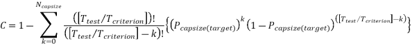
If the model rotorcraft has not capsized during the total duration of the tests, the confidence that the probability of capsizing within 5 minutes is less than the target value of Pcapsize(target), as shown below:
![]()
![]()
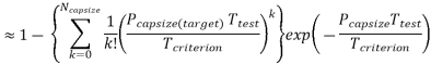
and so the total duration of the model test required without capsize is provided by:
![]()
where:
(A) Ttest is the required full-scale duration of the test (in seconds);
(B) Pcapsize(target) is the required maximum probability of capsizing within 5 minutes;
(C) Tcriterion is the duration (in seconds) in which the rotorcraft must meet the no-capsize probability (= 5 x 60 s), as defined in CS 29.801(e); and
(D) C is the required confidence that the probability of capsizing has been achieved (0.95).
If the rotorcraft has capsized Ncapsize times during the tests, the probability of capsizing within 5 minutes can be estimated as:
![]()
and the confidence that the required capsize criteria have been met is:
It should be noted that, if the rotorcraft is permitted to fly over sea conditions with significant wave heights above the certification limit, then Pcapsize(target) should be reduced by the probability of exceedance of the certification limit for the significant wave height (Pe) (see Appendix 2 below).
(c) Deliverables
(1) A comprehensive report describing the model tests, the facility they were performed in, the model properties, the wave conditions used, the results of the tests, and the method of analysis to demonstrate compliance with CS 29.801(d) and (e).
(2) Conclusions in this report are to clarify the compliance (or otherwise) with those requirements.
(3) Digital video and data records of all tests performed.
(4) A specification for a certification model test should also be expected to include:
(i) an execution plan and time scale;
(ii) formal progress reports on content and frequency; and
(iii) quality assurance requirements.
[Amdt No: 29/5]
ED Decision 2018/007/R
The target 5-minute capsize probabilities for a rotorcraft certified to CS 29.801 are:
Certification with ditching provisions;
Fully serviceable emergency flotation system (EFS) - 3 %
Critical flotation compartment failed - 30 %
Certification with emergency flotation provisions;
Fully serviceable emergency flotation system (EFS) - 10 %
Critical flotation compartment failed - no demonstration required
One option available to the rotorcraft designer is to test at the selected wave height and demonstrate a probability of capsizing no greater than these values. However, to enhance offshore helicopter safety, some national aviation authorities (NAAs) have imposed restrictions that prevent normal operations (i.e. excluding emergencies, search and rescue (SAR), etc.) over sea conditions that are more severe than those for which performance has been demonstrated. In such cases, the helicopter may be operationally limited.
These operational restrictions may be avoided by accounting for the probability of exposure to sea conditions that exceed the selected wave height by certifying the rotorcraft for a lower probability of capsizing. Since it is conservatively assumed that the probability of capsizing in sea conditions that exceed the certified wave height is unity, the lower capsize probability required to be met is the target value minus the probability of the selected wave height being exceeded. However, it should also be noted that, in addition to restricting normal helicopter overwater operations to the demonstrated capability, i.e. the applicant’s chosen significant wave height limit (Hs(limit)), an NAA may declare a maximum limit above which all operations will be suspended due to the difficulty of rescuing persons from the sea in extreme conditions. There will, therefore, be no operational benefit in certifying a rotorcraft for sea conditions that exceed the national limits for rescue.
In the following examples, we shall use the three target probabilities of capsizing without any reduction to avoid operational restrictions. The test times quoted are full-scale times; to obtain the actual model test run time, these times should be divided by the square root of the model scale.
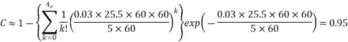
Certification with ditching provisions — fully serviceable EFS
Taking this first case, we need to demonstrate a ≤ 3 % probability of capsizing with a 95 % confidence. Applying equation (5)(i) above, this can be achieved with a 499-minute (full-scale time) exposure to the sea condition without a capsize.
Rearranging this equation, we have:
![]()
![]()
Alternatively, applying equation (5)(ii) above, the criterion would also be met if the model were seen to capsize just three times (for example) in a total 21.5 hours of exposure to the sea condition, or four times (for example) in a total of 25.5 hours of exposure.
Equation (ii) cannot be readily rearranged to solve Ttest, so the easiest way to solve it is by using a spreadsheet on a trial-and-error method. For the four-capsize case, we find that a 25.5-hour exposure gives a confidence of 0.95.
Certification with ditching provisions — critical flotation compartment failed
In this case, we need to demonstrate a ≤ 30 % probability of capsizing with a 95 % confidence. This can be achieved with a 50-minute (full-scale time) exposure to the sea condition without a capsize.
![]()
As above, the criterion would also be met if the model were seen to capsize just three times (for example) in a total 2.2 hours of exposure to the sea condition, or four times (for example) in a total of 2.6 hours of exposure.
Solving by trial and error in a spreadsheet, we find that a 2.6-hour exposure with no more than four capsizes gives a confidence of 0.95.

Certification with emergency flotation provisions — fully serviceable EFS
In this case, we need to demonstrate a ≤ 10 % probability of capsizing with a 95 % confidence. By solving the equations as above, this can be achieved with a 150-minute (full-scale time) exposure to the sea condition without a capsize.
![]()
As above, the criterion would also be met if the model were seen to capsize just three times (for example) in a total 6.5 hours of exposure to the sea condition, or four times (for example) in a total of 7.6 hours of exposure.
Solving by trial and error in a spreadsheet we find that a 7.6-hour exposure with no more than four capsizes gives a confidence of 0.95.
Certification with ditching provisions — critical flotation compartment failed
As stated in CS 29.802(c), no demonstration of capsize resistance is required for the case of the critical float compartment having failed.
This is because the allowed factor of ten increase in the probability of capsizing, as explained in (a)(3) above, results in a probability of 100 %.
[Amdt No: 29/5]
Appendix 2 — Test specification rationale
ED Decision 2018/007/R
(a) Introduction
The overall risk of capsizing within the 5-minute exposure period consists of two components: the probability of capsizing in a given wave condition, and the probability of experiencing that wave condition in an emergency landing on water.
If it is assumed that an emergency landing on water occurs at random and is not linked with weather conditions, the overall risk of a capsize can be established by combining two pieces of information:
(1) The wave climate scatter table, which shows the probability of meeting any particular combination of Hs and Tz. An example scatter table is shown below in Figure 1 — Example of all-year wave scatter table. Each cell of the table contains the probability of experiencing a wave condition with Hs and Tz in the range provided. Thus, the total of all cells in the table adds up to unity.
(2) The probability of a capsize in a 5-minute exposure for each of these height/period combinations. This probability of capsizing is different for each helicopter design and for each wave height/period combination, and is to be established through scale model testing using the method defined above.
In theory, a model test for the rotorcraft design should be performed in the full range of wave height/period combinations covering all the cells in the scatter table. Clearly, wave height/period combinations with zero or very low probabilities of occurrence might be ignored. It might also be justifiably assumed that the probability of a capsize at very high wave heights is unity, and at very low wave heights, it is zero. However, there would still remain a very large number of intermediate wave height/period combinations that would need to be investigated in model tests, and it is considered that such a test programme would be too lengthy and costly to be practicable.
The objective here is therefore to establish a justifiable method of estimating the overall 5-minute capsize probability using model test results for a single-wave condition. That is a single combination of Hs and Tz. Such a method can never be rigorously linked with the safety objective, but it is proposed that it may be regarded as a conservative approximation.
(b) Test methodology
The proposed test methodology is as follows:
The rotorcraft designer selects a desired significant wave height limit Hs(limit) for the certification of his helicopter. Model tests are performed in the sea condition Hs(limit).
Tz(limit) (where Tz(limit) is the zero-crossing period most likely to accompany Hs(limit)) with the selected spectrum shape using the method specified above, and the 5-minute probability of capsizing (Pcapsize) established in this sea condition.
The way in which Pcapsize varies for other values of Hs and Tz is not known because it is not proposed to perform model tests in all the other possible combinations. Furthermore, there is no theoretical method to translate a probability of capsizing from one sea condition to another.
However, it is known that the probability of capsizing is related to the exposure to breaking waves of sufficient height, and that this is in turn linked with wave steepness. Hence:
(1) the probability of capsizing is likely to be higher for wave heights just less than Hs(limit) but with wave periods shorter than Tz(limit); and
(2) the probability of capsizing will be lower for the larger population of wave conditions with wave heights less than Hs(limit) and with wave periods longer than Tz(limit).
So, a reasonable and conservative assumption is that on average, the same Pcapsize holds good for all wave conditions with heights less than or equal to Hs(limit).
A further conservative assumption is that Pcapsize is unity for all wave heights greater than Hs(limit).
Using these assumptions, a comparison of the measured Pcapsize in Hs(limit) Tz(limit) against the target probability of capsizing (Pcapsize(target)) can be performed.
In jurisdictions where flying is not permitted when the wave height is above Hs(limit), the rotorcraft will have passed the certification criteria provided that Pcapsize ≤ Pcapsize(target).
In jurisdictions where flying over waves greater than Hs(limit) is permitted, the rotorcraft will have passed the certification criteria provided that Pcapsize ≤ Pcapsize(target) – Pe, where Pe is the probability of exceedance of Hs(limit). Clearly, in this case, it can be seen that it would not be permissible for the rotorcraft designer to select an Hs(limit) which has a probability of exceedance greater than Pcapsize(target).
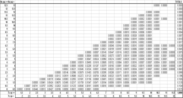
Figure 1 — Example of all-year wave scatter table
[Amdt No: 29/5]
ED Decision 2018/007/R
If operational rules allow, and only certification for emergency flotation equipment is requested by the applicant, the rotorcraft must be designed as follows;
(a) The rotorcraft must be equipped with an approved emergency flotation system.
(b) For a rotorcraft with a passenger seating capacity of 9 or less, the flotation units and their attachments to the rotorcraft must comply with CS 29.563. For a rotorcraft with a passenger seating capacity of 10 or more, the rotorcraft must comply with CS 29.563.
(c) The rotorcraft must be shown to resist capsize in the sea conditions selected by the applicant. The probability of capsizing in a 5-minute exposure to the sea conditions must be demonstrated to be less than or equal to 10.0 % with a fully serviceable emergency flotation system, with 95 % confidence. No demonstration of capsize resistance is required for the case of the critical float compartment having failed.
Allowances must be made for probable structural damage and leakage.
(d) It must be shown that the rotorcraft will not sink following the functional loss of any single complete flotation unit.
[Amdt No: 29/5]
AMC 29.802 Emergency Flotation
ED Decision 2018/007/R
This AMC replaces FAA AC 29 MG 10.
(a) Definitions
(1) Ditching: a controlled emergency landing on water, deliberately executed in accordance with rotorcraft flight manual (RFM) procedures, with the intent of abandoning the rotorcraft as soon as practicable.
NOTE: Although the term ‘ditching’ is most commonly associated with the design standards related to CS 29.801, a rotorcraft equipped to the less demanding requirements of CS 29.802, when performing an emergency landing on water, would nevertheless be commonly described as carrying out the process of ditching. The term ‘ditching’ is therefore used in this AMC in this general sense.
(2) Emergency flotation system (EFS): a system of floats and any associated parts (e.g. gas cylinders, means of deployment, pipework and electrical connections) that is designed and installed on a rotorcraft to provide buoyancy and flotation stability in a ditching.
(b) Explanation
(1) Approval of emergency flotation equipment is performed only if requested by the applicant. Operational rules may accept that a helicopter conducts flights over certain sea areas provided it is fitted with approved emergency flotation equipment (i.e. an EFS), rather than being certified with full ditching provisions.
(2) Emergency flotation certification encompasses emergency flotation system loads (as specified in CS 29.802) and design, and rotorcraft flotation stability.
(3) Failure of the EFS to operate when required will lead to the rotorcraft rapidly capsizing and sinking. Operational experience has shown that localised damage or failure of a single component of an EFS can lead to the loss of the complete system. Therefore, the design of the EFS needs careful consideration.
(4) The sea conditions on which certification with emergency flotation is to be based are selected by the applicant and should take into account the expected sea conditions in the intended areas of operation. Capsize resistance is required to meet the same requirements as for full ditching approval, but with the allowable capsize probability being set at 10 %. The default wave climate specified in this requirement is that of the northern North Sea, as it represents a conservative condition. This might be considered inappropriate in so far as it represents a hostile sea area. The applicant may therefore propose a different wave climate based on data from a non-hostile sea area. The associated certification will then be limited to the geographical region(s) thus represented. Alternatively, a non-hostile default wave climate might be agreed, with no associated need for geographical limits to the certification. The significant wave height, and any geographical limitations (if applicable, see the AMC to 29.801(e) and 29.802(c)) should be included in the RFM as performance information.
(5) During scale model testing, appropriate allowances should be made for probable structural damage and leakage. Previous model tests and other data from rotorcraft of similar configurations that have already been substantiated based on equivalent test conditions may be used to satisfy the emergency flotation requirements. In regard to flotation stability, test conditions should be equivalent to those defined in the AMC to 29.801(e) and 29.802(c).
(6) CS 29.802 requires that in sea conditions for which certification with emergency flotation is requested by the applicant, the probability of capsizing in a 5-minute exposure is acceptably low in order to allow the occupants to leave the rotorcraft and enter the life rafts. This should be interpreted to mean that up to and including the worst-case sea conditions for which certification with emergency flotation is requested by the applicant, the probability that the rotorcraft will capsize should be not higher than the target stated in CS 29.802(c). An acceptable means of demonstrating post-ditching flotation stability is through scale model testing using irregular waves. The AMC to 29.801(e) and 29.802(c) contains a test specification that has been developed for this purpose.
(7) Providing a ‘wet floor’ concept (water in the cabin) by positioning the floats higher on the fuselage sides and allowing the rotorcraft to float lower in the water can be a way of increasing the stability of a ditched rotorcraft (although this would need to be verified for the individual rotorcraft type for all weight and loading conditions), or it may be desirable for other reasons. This is permissible provided that the mean static level of water in the cabin is limited to being lower than the upper surface of the seat cushion (for all rotorcraft mass and centre of gravity cases, with all flotation units intact), and that the presence of water will not unduly restrict the ability of occupants to evacuate the rotorcraft and enter the life raft.
(8) The sea conditions approved for ditching should be stated in the performance information section of the RFM.
(9) It should be shown by analysis or other means that the rotorcraft will not sink following the functional loss of any single complete ditching flotation unit. Experience has shown that in water-impact events, the forces exerted on the emergency flotation unit that first comes into contact with the water surface, together with structural deformation and other damage, can render the unit unusable. Maintenance errors may also lead to a flotation unit failing to inflate. The ability of occupants to egress successfully is significantly increased if the rotorcraft does not sink. However, this requirement is not intended for any other purpose, such as aiding in the salvage of the rotorcraft. Therefore, consideration of the remaining flotation units remaining inflated for an especially long period, i.e. longer than required in the upright floating case, is not required.
(c) Procedures
(1) Flotation system design
(i) Structural integrity should be established in accordance with CS 29.563. For a rotorcraft with a seating capacity of maximum 9 passengers, CS 29.802(a) only requires the floats and their attachments to the rotorcraft to be designed to withstand the load conditions defined in CS 29.563. Other parts of the rotorcraft (e.g. fuselage underside structure, chin windows, doors) do not need to be shown to be capable of withstanding these load conditions. All parts of rotorcraft with a seating capacity of 10 passengers of more should be designed to withstand the load conditions defined in CS 29.563 (i.e. the same design standards as for full ditching approval).
(ii) Rotorcraft handling qualities should be verified to comply with the applicable certification specifications throughout the approved flight envelope with floats installed. Where floats are normally deflated and deployed in flight, the handling qualities should be verified for the approved operating envelopes with the floats in:
(A) the deflated and stowed condition;
(B) the fully inflated condition; and
(C) the in-flight inflation condition; for float systems which may be inflated in flight, rotorcraft controllability should be verified by test or analysis taking into account all possible emergency flotation system inflation failures.
(iii) Reliability should be considered in the basic design to assure approximately equal inflation of the floats to preclude excessive yaw, roll, or pitch in flight or in the water:
(A) Maintenance procedures should not degrade the flotation system (e.g. introducing contaminants that could affect normal operation, etc.).
(B) The flotation system design should preclude inadvertent damage due to normal personnel traffic flow and wear and tear. Protection covers should be evaluated for function and reliability.
(C) The designs of the floats should provide means to minimise the likelihood of damage or tear propagation between compartments. Single compartment float designs should be avoided.
(iv) The floats should be fabricated from highly conspicuous material to assist in locating the rotorcraft following a ditching (and possible capsize).
(2) Flotation system inflation
Emergency flotation systems (EFSs) which are normally stowed in a deflated condition and are inflated either in flight or after water contact should be evaluated as follows:
(i) The emergency flotation system should include a means to verify system integrity prior to each flight.
(ii) If a manual means of inflation is provided, the float activation switch should be located on one of the primary flight controls and should be safeguarded against inadvertent actuation.
(iii) The maximum airspeeds for intentional in-flight actuation of the emergency flotation system and for flight with the floats inflated should be established as limitations in the RFM unless in-flight actuation is prohibited by the RFM.
(iv) Activation of the emergency flotation system upon water entry (irrespective of whether or not inflation prior to water entry is the intended operation mode) should result in an inflation time short enough to prevent the rotorcraft from becoming excessively submerged.
(v) A means should be provided for checking the pressure of the gas stowage cylinders prior to take-off. A table of acceptable gas cylinder pressure variation with ambient temperature and altitude (if applicable) should be provided.
(vi) A means should be provided to minimise the possibility of over-inflation of the flotation units under any reasonably probable actuation conditions.
(vii) The ability of the floats to inflate without puncturing when subjected to actual water pressures should be substantiated. A demonstration of a full-scale float immersion in a calm body of water is one acceptable method of substantiation. Precautions should also be taken to avoid floats being punctured due to the proximity of sharp objects, during inflation in flight or with the helicopter in the water, and during subsequent movement of the helicopter in waves. Examples of objects that need to be considered are aerials, probes, overboard vents, unprotected split-pin tails, guttering and any projections sharper than a three dimensional right angled corner.
(viii) CS 29.802(d) requires the rotorcraft to not sink following the functional loss of any complete flotation unit. Complete flotation unit shall be taken to mean a discrete, independently located float. The qualifying term ‘complete’ means that the entire structure of the flotation unit must be considered, not limited to any segregated compartments.
The loss of function of a flotation unit is most likely to be due to damage that occurs in a water impact. However, there may be other reasons, such as undetected damage during maintenance, or incorrect maintenance. All reasonably probable causes for the loss of functionality of a flotation unit, and the resultant effect(s) on the remainder of the inflation system, should therefore be taken into account.
In the case of inflatable flotation units, irrespective of whether the intended operation is to deploy the system before or after water entry, the following shall be taken into account when assessing the ability of the rotorcraft to remain afloat;
— Following the functional loss of a deployed flotation unit, the capability to maintain pressure in the remaining inflation units should be justified on the basis of the design of the inflation system, for example:
— individual inflation gas sources per flotation unit;
— installation of non-return valves at appropriate locations.
— Following the functional loss of a non-deployed flotation unit, the capability of the remaining flotation units to deploy should be justified on the basis of the design of the inflation system, for example:
— functionality of inflation gas sources integrated with the functionally lost flotation unit in question should also either be assumed to be lost, or justification for otherwise provided;
— the degree of inflation of remaining undamaged flotation units, which share parts of the inflation system with the damaged unit, bearing in mind the damaged unit will be venting, should be determined.
(3) Injury prevention during and following water entry.
An assessment of the cabin and cockpit layouts should be undertaken to minimise the potential for injury to occupants in a ditching. This may be performed as part of the compliance with CS 29.785. Attention should be given to the avoidance of injuries due to leg/arm flailing, as these can be a significant impediment to occupant egress and subsequent survivability. Practical steps that could be taken include:
(i) locating potentially hazardous items away from the occupants;
(ii) installing energy-absorbing padding onto interior components;
(iii) using frangible materials; and
(iv) designs that exclude hard or sharp edges.
(4) Water entry procedures.
Tests or simulations (or a combination of both) should be conducted to establish procedures and techniques to be used for water entry. These tests/simulations should include determination of the optimum pitch attitude and forward velocity for ditching in a calm sea, as well as entry procedures for the most severe sea condition to be certified. Procedures for all failure conditions that may lead to a ‘land immediately’ action (e.g. one engine inoperative, all engines inoperative, tail rotor/drive failure) should be established.
(5) Flotation stability tests.
An acceptable means of flotation stability testing is contained in AMC to 29.801(e) and 29.802(c). Note that model tests in a wave basin on a number of different rotorcraft types have indicated that an improvement in seakeeping performance can consistently be achieved by fitting float scoops.
(6) Occupant egress and survival.
The ability of the occupants to deploy life rafts, egress the rotorcraft, and board the life rafts should be evaluated. For configurations which are considered to have critical occupant egress capabilities due to the life raft locations or the emergency exit locations and proximity of the float (or a combination of both), an actual demonstration of egress may be required. When a demonstration is required, it may be conducted on a full-scale rotorcraft actually immersed in a calm body of water or using any other rig or ground test facility shown to be representative. The demonstration should show that floats do not impede a satisfactory evacuation. Service experience has shown that it is possible for occupants to have escaped from the cabin but to have not been able to board a life raft and to have had difficulty in finding handholds to stay afloat and together. Handholds or lifelines should be provided on appropriate parts of the rotorcraft. The normal attitude of the rotorcraft and the possibility of a capsize should be considered when positioning the handholds or lifelines.
[Amdt No: 29/5]
CS 29.803 Emergency evacuation
ED Decision 2018/007/R
(a) Each crew and passenger area must have means for rapid evacuation in a crash landing, with the landing gear:
(1) extended; and
(2) retracted;
considering the possibility of fire.
(b) Passenger entrance, crew, and service doors may be considered as emergency exits if they meet the requirements of this paragraph and of CS 29.805 to 29.815.
(c) If certification with ditching provisions is requested by the applicant:
(1) ditching emergency exits must be provided such that following a ditching, in all sea conditions for which ditching capability is requested by the applicant, passengers are able to evacuate the rotorcraft and step directly into any of the required life rafts;
(2) any exit provided for compliance with (1), irrespective of whether it is also required by any of the requirements of CS 29.807, must meet all the requirements of CS 29.809(c), CS 29.811(a), (c), (d), (e) and CS 29.812(b); and
(3) flotation devices, whether stowed or deployed, may not interfere with or obstruct the ditching emergency exits.
(d) Except as provided in sub-paragraph (e), the following categories of rotorcraft must be tested in accordance with the requirements of Appendix D to demonstrate that the maximum seating capacity, including the crew-members required by the operating rules, can be evacuated from the rotorcraft to the ground within 90 seconds:
(1) Rotorcraft with a seating capacity of more than 44 passengers.
(2) Rotorcraft with all of the following:
(i) Ten or more passengers per passenger exit as determined under CS 29.807(b).
(ii) No main aisle, as described in CS 29.815, for each row of passenger seats.
(iii) Access to each passenger exit for each passenger by virtue of design features of seats, such as folding or break-over seat backs or folding seats.
(e) A combination of analysis and tests may be used to show that the rotorcraft is capable of being evacuated within 90 seconds under the conditions specified in CS 29.803(d) if the Agency finds that the combination of analysis and tests will provide data, with respect to the emergency evacuation capability of the rotorcraft, equivalent to that which would be obtained by actual demonstration.
[Amdt No: 29/5]
Appendix D – Criteria for demonstration of emergency evacuation procedures under CS 29.803
ED Decision 2003/16/RM
(a) The demonstration must be conducted either during the dark of the night or during daylight with the dark of night simulated. If the demonstration is conducted indoors during daylight hours, it must be conducted inside a darkened hangar having doors and windows covered. In addition, the doors and windows of the rotorcraft must be covered if the hangar illumination exceeds that of a moonless night. Illumination on the floor or ground may be used, but it must be kept low and shielded against shining into the rotorcraft’s windows or doors.
(b) The rotorcraft must be in a normal attitude with landing gear extended.
(c) Safety equipment such as mats or inverted liferafts may be placed on the floor or ground to protect participants. No other equipment that is not part of the rotorcraft’s emergency evacuation equipment may be used to aid the participants in reaching the ground.
(d) Except as provided in paragraph (a), only the rotorcraft’s emergency lighting system may provide illumination.
(e) All emergency equipment required for the planned operation of the rotorcraft must be installed.
(f) Each external door and exit and each internal door or curtain must be in the take-off configuration.
(g) Each crewmember must be seated in the normally assigned seat for take-off and must remain in that seat until receiving the signal for commencement of the demonstration. For compliance with this paragraph, each crewmember must be:
(1) A member of a regularly scheduled line crew; or
(2) A person having knowledge of the operation of exits and emergency equipment.
(h) A representative passenger load of persons in normal health must be used as follows:
(1) At least 25% must be over 50 years of age, with at least 40% of these being females.
(2) The remaining 75% or less, must be 50 years of age or younger, with at least 30% of these being females.
(3) Three life-size dolls, not included as part of the total passenger load, must be carried by passengers to simulate live infants 2 years old or younger, except for a total passenger load of fewer than 44 but more than 19, one doll must be carried. A doll is not required for a 19 or fewer passenger load.
(4) Crewmembers, mechanics, and training personnel who maintain or operate the rotorcraft in the normal course of their duties may not be used as passengers.
(i) No passenger may be assigned a specific seat except as the Agency may require. Except as required by paragraph (g), no employee of the applicant may be seated next to an emergency exit, except as allowed by the Agency.
(j) Seat belts and shoulder harnesses (as required) must be fastened.
(k) Before the start of the demonstration, approximately one-half of the total average amount of carry-on baggage, blankets, pillows and other similar articles must be distributed at several locations in the aisles and emergency exit access ways to create minor obstructions.
(l) No prior indication may be given to any crewmember or passenger of the particular exits to be used in the demonstration.
(m) There must not be any practising, rehearsing or description of the demonstration for the participants nor may any participant have taken part in this type of demonstration within the preceding 6 months.
(n) A pre-take-off passenger briefing may be given. The passengers may also be advised to follow directions of crewmembers, but not be instructed on the procedures to be followed in the demonstration.
(o) If safety equipment, as allowed by paragraph (c), is provided, either all passenger and cockpit windows must be blacked out or all emergency exits must have safety equipment to prevent disclosure of the available emergency exits.
(p) Not more than 50% of the emergency exits in the sides of the fuselage of a rotorcraft that meet all of the requirements applicable to the required emergency exits for that rotorcraft may be used for demonstration. Exits that are not to be used for the demonstration must have the exit handle deactivated or must be indicated by red lights, red tape, or other acceptable means placed outside the exits to indicate fire or other reasons why they are unusable. The exits to be used must be representative of all the emergency exits on the rotorcraft and must be designated subject to approval by the Agency. If installed, at least one floor level exit (Type I; CS 29.807(a)(1)) must be used as required by CS 29.807(c).
(q) All evacuees must leave the rotorcraft by a means provided as part of the rotorcraft’s equipment.
(r) Approved procedures must be fully utilised during the demonstration.
(s) The evacuation time period is completed when the last occupant has evacuated the rotorcraft and is on the ground.
AMC 29.803(c) Emergency evacuation
ED Decision 2018/007/R
This AMC supplements FAA AC 29.803 and AC 29.803A.
(a) Explanation
At Amendment 5, the usage of the term ‘ditching emergency exit’ was changed.
CS 29.803(c) was created with the intention that the rotorcraft design will allow all passengers to egress the rotorcraft and enter a life raft without undue effort or skill, and with a very low risk of falling and entering the water surrounding of the ditched rotorcraft. Boarding a life raft from the water is difficult, even in ideal conditions, and survival time is significantly increased once aboard a life raft, particularly if the survivor has remained at least partly dry. CS 29.803(c) requires that ditching emergency exits be provided to facilitate boarding into each of the required life rafts.
(b) Procedures
(1) The general arrangement of most rotorcraft and the location of the deployed life rafts may be such that the normal entry/egress doors will best facilitate entry to a life raft. It should also be substantiated that the life rafts can be restrained in a position that allows passengers to step directly from the cabin into the life rafts. This is expected to require provisions to enable a cabin occupant to pull the deployed life raft to the exit, using the retaining line, and maintain it in that position while others board.
(2) It is not considered disadvantageous if opening the normal entry/egress doors will result in water entering the cabin provided that the depth of water would not be such as to hinder evacuation. However, it should be substantiated that water pressure on the door will not excessively increase operating loads.
(3) If exits such as normal entry/egress doors, which are not already being used to meet the requirements for emergency exits or underwater emergency exits (or both), are used for compliance with CS 29.803(c)(1), they should be designed to meet certain of the standards applied to emergency exits. Their means of opening should be simple and obvious and not require exceptional effort (see CS 29.809(c)), their means of access and opening should be conspicuously marked, including in the dark (see CS 29.811(a)), their location should be indicated by signs (see CS 29.811(c) and (d)), and their operating handles should be clearly marked (see CS 29.811(e)).
[Amdt No: 29/5]
CS 29.805 Flight crew emergency exits
ED Decision 2018/007/R
(a) For rotorcraft with passenger emergency exits that are not convenient to the flight crew, there must be flight crew emergency exits, on both sides of the rotorcraft or as a top hatch, in the flight crew area.
(b) Each flight crew emergency exit must be of sufficient size and must be located so as to allow rapid evacuation of the flight crew. This must be shown by test.
(c) Underwater emergency exits for flight crew. If certification with ditching provisions is requested by the applicant, none of the flight crew emergency exits required by (a) and (b) may be obstructed by water or flotation devices after a ditching and each exit must be shown by test, demonstration, or analysis to provide for rapid escape when the rotorcraft is in the upright floating position or capsized. Each operational device (pull tab(s), operating handle, ‘push here’ decal, etc.) must be shown to be accessible for the range of flight crew heights as required by CS 29.777(b) and for both the case of an un-deformed seat and a seat with any deformation resulting from the test conditions required by CS 29.562.
[Amdt No: 29/5]
AMC 29.805(c) Flight crew emergency exits
ED Decision 2018/007/R
This AMC supplements FAA AC 29.805 and replaces AC 29.805A.
(a) Explanation
To facilitate a rapid escape, flight crew underwater emergency exits should be designed for use with the rotorcraft in both the upright position and in any foreseeable floating attitude. The flight crew underwater emergency exits should not be obstructed during their operation by water or floats to the extent that rapid escape would not be possible or that damage to the flotation system may occur. This should be substantiated for any rotorcraft floating attitude, upright or capsized, and with the emergency flotation system intact and with any single compartment failed. With the rotorcraft capsized and floating, the flight crew emergency exits should be usable with the cabin flooded.
(b) Procedures
(1) It should be shown by test, demonstration or analysis that there is no interference with the flight crew underwater emergency exits from water or from any stowed or deployed emergency flotation devices, with the rotorcraft in any foreseeable floating attitude.
(2) Flight crew should be able to reach the operating device for their underwater emergency exit, whilst seated, with restraints fastened, with seat energy absorption features at any design position, and with the rotorcraft in any attitude.
(3) Likely damage sustained during a ditching should be considered.
(4) It is acceptable for the underwater emergency exit threshold to be below the waterline when the rotorcraft is floating upright, but in such a case, it should be substantiated that there is no obstruction to the use of the exit and that no excessive force (see FAA AC 29.809) is required to operate the exit.
(5) It is permissible for flight crew to be unable to directly enter life rafts from the flight crew underwater emergency exits and to have to take a more indirect route, e.g. by climbing over a forward flotation unit. In such a case, the feasibility of the exit procedure should be assessed. Handholds may need to be provided on the rotorcraft.
(6) To make it easier to recognise underwater, the operating device for the underwater emergency exit should have black and yellow markings with at least two bands of each colour of approximately equal widths. Any other operating feature, e.g. highlighted ‘push here’ decal(s) for openable windows, should also incorporate black-and-yellow-striped markings.
[Amdt No: 29/5]
CS 29.807 Passenger emergency exits
ED Decision 2018/007/R
(a) Type. For the purpose of this CS-29, the types of passenger emergency exit are as follows:
(1) Type I. This type must have a rectangular opening of not less than 0.61 m wide by 1.22 m (24 inches wide by 48 inches) high, with corner radii not greater than one-third the width of the exit, in the passenger area in the side of the fuselage at floor level and as far away as practicable from areas that might become potential fire hazards in a crash.
(2) Type II. This type is the same as Type I, except that the opening must be at least 0.51 m wide by 1.12 m (20 inches wide by 44 inches) high.
(3) Type III. This type is the same as Type I, except that:
(i) The opening must be at least 0.51 m wide by 0.91 m (20 inches wide by 36 inches) high; and
(ii) The exits need not be at floor level.
(4) Type IV. This type must have a rectangular opening of not less than 0.48 m wide by 0.66 m (19 inches wide by 26 inches) high, with corner radii not greater than one-third the width of the exit, in the side of the fuselage with a step-up inside the rotorcraft of not more than 0.74 m (29 inches).
Openings with dimensions larger than those specified in this paragraph may be used, regardless of shape, if the base of the opening has a flat surface of not less than the specified width.
(b) Passenger emergency exits: side-of fuselage. Emergency exits must be accessible to the passengers and, except as provided in sub-paragraph (d), must be provided in accordance with the following table:
|
Passenger seating capacity |
Emergency exits for each side of the fuselage |
|||
|
(Type I) |
(Type II) |
(Type III) |
(Type IV) |
|
|
1 to 10 |
|
|
|
1 |
|
11 to 19 |
|
|
1 or |
2 |
|
20 to 39 |
|
1 |
|
1 |
|
40 to 59 |
1 |
|
|
1 |
|
60 to 79 |
1 |
|
1 or |
2 |
(c) Passenger emergency exits; other than side of-fuselage. In addition to the requirements of subparagraph (b):
(1) There must be enough openings in the top, bottom, or ends of the fuselage to allow evacuation with the rotorcraft on its side; or
(2) The probability of the rotorcraft coming to rest on its side in a crash landing must be extremely remote.
(d) Underwater emergency exits for passengers. If certification with ditching provisions is requested by the applicant, underwater emergency exits must be provided in accordance with the following requirements and must be proven by test, demonstration, or analysis to provide for rapid escape with the rotorcraft in the upright floating position or capsized.
(1) One underwater emergency exit in each side of the rotorcraft, meeting at least the dimensions of a Type IV exit for each unit (or part of a unit) of four passenger seats. However, the passenger seat-to-exit ratio may be increased for exits large enough to permit the simultaneous egress of two passengers side by side.
(2) Flotation devices, whether stowed or deployed, may not interfere with or obstruct the underwater emergency exits.
(e) Ramp exits. One Type I exit only, or one Type II exit only, that is required in the side of the fuselage under sub-paragraph (b), may be installed instead in the ramp of floor ramp rotorcraft if:
(1) Its installation in the side of the fuselage is impractical; and
(2) Its installation in the ramp meets CS 29.813.
(f) Tests. The proper functioning of each emergency exit must be shown by test.
[Amdt No: 29/5]
AMC 29.807(d) Underwater emergency exits for passengers
ED Decision 2018/007/R
This AMC replaces FAA AC 29.807 and AC 29.807A.
(a) Explanation
CS-29 Amendment 5 re-evaluates the need for and the concept behind emergency exits for rotorcraft approved with ditching provisions. Prior to CS-29 Amendment 5, rotorcraft that had a passenger seating configuration, excluding pilots’ seats, of nine seats or less were required to have one emergency exit above the waterline in each side of the rotorcraft, having at least the dimensions of a Type IV exit. For rotorcraft that had a passenger seating configuration, excluding pilots’ seats, of 10 seats or more, one emergency exit was required to be located above the waterline in one side of the rotorcraft and to have at least the dimensions of a Type III exit, for each unit (or part of a unit) of 35 passenger seats, but no less than two such exits in the passenger cabin, with one on each side of the rotorcraft. These exits were referred to as ‘ditching emergency exits’.
Operational experience has shown that in a ditching in which the rotorcraft remains upright, use of the passenger doors can be very beneficial in ensuring a rapid and orderly evacuation onto the life raft(s). However, when a rotorcraft capsizes, doors may be unusable and the number and availability of emergency exits that can be readily used underwater will be crucial to ensuring that passengers are able to escape in a timely manner. Experience has shown that the number of emergency exits required in the past by design requirements has been inadequate in a capsized situation, and a common design solution has been to use the passenger cabin windows as additional emergency egress means by including a jettison feature. The jettison feature has commonly been provided by modifying the elastomeric window seal such that its retention strength is either reduced, or can be reduced by providing a removable part of its cross section, i.e. the so called ‘push out’ window, although other design solutions have been employed. The provision of openable windows has been required by some air operations regulations.
In recognition of this identified need for an increased number of exits for underwater escape, Amendment 5 created a new set of exit terminology and CS 29.807(d)(1) was revised to require one pair of ‘underwater emergency exits’, i.e. one on each side of the rotorcraft, to be provided for each unit, or part of a unit, of four passenger seats.
This new terminology was seen as better describing the real intent of this higher number of required emergency exits for rotorcraft approved with ditching provisions.
Furthermore, CS 29.813(d)(1) requires passenger seats to be located relative to these exits in a way that best facilitates escape. The objective is for no passenger to be in a worse position than the second person to egress through an exit. The size of each underwater emergency exit should at least have the dimensions of a Type IV exit (0.48 m x 0.66 m or 19 in. x 26 in.).
The term ‘ditching emergency exit’ is retained for the exits required by the newly created CS 29.803(c). These exits are required to enable passengers to step directly into the life rafts when the rotorcraft remains upright. This is the normally expected case in a ditching and thus it is considered that this term is appropriate to describe these exits.
It is intended that training and briefing materials for passengers carried on helicopters that meet these new requirements will be designed to reflect the two types of emergency exits (ditching and underwater emergency exits) and the two associated scenarios that are assumed for their intended use (directly boarding a life raft from an upright helicopter following ditching, and immediate underwater escape should the helicopter capsize, respectively).
(b) Procedures
(1) The number and the size of underwater emergency exits should be as specified in paragraph (a) above.
(2) Care should be taken regarding oversized exits to avoid them becoming blocked if more than one passenger attempts to use the same exit simultaneously.
(3) A higher seat-to-exit ratio may be accepted if the exits are large enough to allow the simultaneous escape of more than one passenger. For example, a pair of exits may be approved for eight passengers if the size of each exit provides an unobstructed area that encompasses two ellipses of 0.48 m x 0.66 m (19 in. x 26 in.) side by side.
(4) Test, demonstration, compliance inspection, or analysis is required to substantiate that an exit is free from interference from stowed or deployed emergency flotation devices. In the event that an analysis or inspection is insufficient or that a given design is questionable, a test or demonstration may be required. Such a test or demonstration would consist of an accurate, full-size replica (or true representation) of the rotorcraft and its flotation devices, both while stowed and after their deployment.
(5) The cabin layout should be designed so that the seats are located relative to the underwater emergency exits in compliance with CS 29.813(d)(1).
[Amdt No: 29/5]
CS 29.809 Emergency exit arrangement
ED Decision 2018/007/R
(a) Each emergency exit must consist of a door, openable window, or hatch in the external walls of the fuselage and must provide an unobstructed opening to the outside.
(b) Each emergency exit must be openable from the inside and from the outside.
(c) The means of opening each emergency exit must be simple and obvious and may not require exceptional effort.
(d) There must be means for locking each emergency exit and for preventing opening in flight inadvertently or as a result of mechanical failure.
(e) There must be means to minimise the probability of the jamming of any emergency exit in a minor crash landing as a result of fuselage deformation under the ultimate inertial forces in CS 29.783(d).
(f) Except as provided in sub-paragraph (h), each land-based rotorcraft emergency exit must have an approved slide as stated in sub-paragraph (g), or its equivalent, to assist occupants in descending to the ground from each floor level exit and an approved rope, or its equivalent, for all other exits, if the exit threshold is more than 1.8 m (6 ft) above the ground:
(1) With the rotorcraft on the ground and with the landing gear extended;
(2) With one or more legs or part of the landing gear collapsed, broken, or not extended; and
(3) With the rotorcraft resting on its side, if required by CS 29.803(d).
(g) The slide for each passenger emergency exit must be a self-supporting slide or equivalent, and must be designed to meet the following requirements:
(1) It must be automatically deployed, and deployment must begin during the interval between the time the exit opening means is actuated from inside the rotorcraft and the time the exit is fully opened. However, each passenger emergency exit which is also a passenger entrance door or a service door must be provided with means to prevent deployment of the slide when the exit is opened from either the inside or the outside under non-emergency conditions for normal use.
(2) It must be automatically erected within 10 seconds after deployment is begun.
(3) It must be of such length after full deployment that the lower end is self-supporting on the ground and provides safe evacuation of occupants to the ground after collapse of one or more legs or part of the landing gear.
(4) It must have the capability, in 12.9 m/s (25-knot) winds directed from the most critical angle, to deploy and, with the assistance of only one person, to remain usable after full deployment to evacuate occupants safely to the ground.
(5) Each slide installation must be qualified by five consecutive deployment and inflation tests conducted (per exit) without failure, and at least three tests of each such five-test series must be conducted using a single representative sample of the device. The sample devices must be deployed and inflated by the system’s primary means after being subjected to the inertia forces specified in CS 29.561(b). If any part of the system fails or does not function properly during the required tests, the cause of the failure or malfunction must be corrected by positive means and after that, the full series of five consecutive deployment and inflation tests must be conducted without failure.
(h) For rotorcraft having 30 or fewer passenger seats and having an exit threshold of more than 1.8 m (6 ft) above the ground, a rope or other assist means may be used in place of the slide specified in sub-paragraph (f), provided an evacuation demonstration is accomplished as prescribed in CS 29.803(d) or (e).
(i) If a rope, with its attachment, is used for compliance with sub-paragraph (f), (g) or (h), it must -
(1) Withstand a 182 kg (400-pound) static load; and
(2) Attach to the fuselage structure at or above the top of the emergency exit opening, or at another approved location if the stowed rope would reduce the pilot’s view in flight.
(j) If certification with ditching provisions is requested by the applicant, each underwater emergency exit must meet the following:
(1) means of operation, markings, lighting and accessibility, must be designed for use in a flooded and capsized cabin;
(2) it must be possible for each passenger to egress the rotorcraft via the nearest underwater emergency exit, when capsized, with any door in the open and secured position; and
(3) a suitable handhold, or handholds, adjacently located inside the cabin to assist passengers in locating and operating the exit, as well as in egressing from the exit, must be provided.
[Amdt No: 29/5]
AMC 29.809 Emergency exit arrangement
ED Decision 2018/007/R
This AMC supplements FAA AC 29.809 and AC 29.809A.
(a) Explanation
CS 29.809 covers all types of emergency exit. These may be a door, openable window or hatch. These terms are used to cover the three generic types expected. The term door implies a floor level, or close to floor level, opening. Openable window is self-explanatory, and hatch is used for any other configuration, irrespective of its location or orientation, e.g. located in the cabin ceiling, side wall or floor.
CS-29 Amendment 5 added a new requirement (j) to CS 29.809 related to the design, installation and operation of underwater emergency exits. Underwater emergency exits should be optimised for use with the rotorcraft capsized and flooded.
So-called ‘push-out’ windows (see AMC 29.807(d)) have some advantages in that they are not susceptible to jamming and may open by themselves in a water impact due to flexing of the fuselage upon water entry and/or external water pressure.
Openable windows might require an appreciable pushing force from the occupant. When floating free inside a flooded cabin, and perhaps even if still seated, generation of this force may be difficult. An appropriately positioned handhold or handholds adjacent to the underwater emergency exit(s) should be provided to facilitate an occupant in generating the opening force. Additionally, in the design of the handhold, consideration should be given to it assisting in locating the underwater emergency exit and in enabling buoyancy forces to be overcome during egress.
Consideration should be given to reducing the potential confusion caused by the lack of standardisation of the location of the operating devices (pull tab, handle) for underwater emergency exits. For instance, the device could be located next to the handhold. The occupant then has only to find the handhold to locate the operating device. Each adjacent occupant should be able to reach the handhold and operating device whilst seated, with restraints fastened, with seat energy absorption features in any design position, and with the rotorcraft in any attitude. If a single underwater emergency exit is designed for the simultaneous egress of two occupants side by side, a handhold and an operating device should be within reach of each occupant seated adjacent to the exit.
The risk of a capsize during evacuation onto the life rafts can be mitigated to some extent by instructing passengers to open all the underwater emergency exits as a matter of course soon after the helicopter has alighted on the water, thus avoiding the delay due to opening the exits in the event that the exits are needed. This may be of particular benefit where the helicopter has a ditching emergency exit which overlaps one or more underwater emergency exits when open (e.g. a sliding door). Such advice should be considered for inclusion in the documentation provided to the helicopter operator.
(b) Procedures
(1) Underwater emergency exits should be shown to be operable with the rotorcraft in any foreseeable floating attitude, including with the rotorcraft capsized.
A particular issue exists in regard to doors (e.g. a sliding door) which overlap underwater emergency exits when open, and which are designated as the ditching emergency exits as required by CS 29.803(c). In the case of a rotorcraft with such an arrangement, it should be substantiated that passengers could still have a viable egress route should the helicopter capsize after the door has been opened but before all occupants have egressed.
Where the open door does not offer an opening of sufficient size and location to provide immediate and usable underwater egress possibility for all occupants, wherever they are located, the intent could be achieved by opening two push-out windows, one in the fuselage and one in the open door. Such a solution will depend on the rotorcraft design ensuring that the windows will be sufficiently aligned when the door is fully opened and secured (the resultant unobstructed opening should permit at least an ellipse of 0.48 m x 0.66 m (19 in. x 26 in.) to pass through it). Availability of such an opening is more likely if the windows are opened by cabin occupants as a matter of course following a ditching, as explained in (a) above.
(2) Underwater emergency exits should be designed so that they are optimised for use with the rotorcraft capsized. For example, the handhold(s) should be located close to the bottom of the window (top if inverted) to assist an occupant in overcoming the buoyancy loads of an immersion suit, and it should be ensured that markings and lighting will help identify the exit(s)and readily assist in an escape.
(3) The means to open an underwater emergency exit should be simple and obvious and should not require any exceptional effort. Designs with any of the following characteristics (non-exhaustive list) are considered to be non-compliant:
(i) more than one hand is needed to operate the exit itself (use of the handhold may occupy the other hand);
(ii) any part of the opening means, e.g. an operating handle or control, is located remotely from the exit such that it would be outside of a person’s direct vision when looking directly at the exit, or that the person should move away from the immediate vicinity of the exit in order to reach it; and
(iii) the exit does not meet the opening effort limitations set by FAA AC 29.809.
(4) It should be possible to readily grasp and operate any operating handle or control using either a bare or a gloved hand.
(5) Handholds, as required by CS 29.809(j)(3), should be mounted close to the bottom of each underwater emergency exit such that they fall easily to hand for a normally seated occupant. In the case of exits between face-to-face seating, the provision of two handholds is required. Handholds should be designed such that the risk is low of escapees’ clothing or emergency equipment snagging on them.
(6) The operating handle or tab for underwater emergency exits should be located next to the handhold.
[Amdt No: 29/5]
CS 29.811 Emergency exit marking
ED Decision 2018/007/R
(a) Each emergency exit, its means of access, and its means of opening must be conspicuously marked for the guidance of occupants using the exits in daylight or in the dark.
(b) The identity and location of each passenger emergency exit must be recognisable from a distance equal to the width of the cabin.
(c) The location of each passenger emergency exit must be indicated by a sign visible to occupants approaching along the main passenger aisle. There must be a locating sign:
(1) Next to or above the aisle near each floor emergency exit, except that one sign may serve two exits if both exits can be seen readily from that sign; and
(2) On each bulkhead or divider that prevents fore and aft vision along the passenger cabin, to indicate emergency exits beyond and obscured by it, except that if this is not possible the sign may be placed at another appropriate location.
(d) Each passenger emergency exit marking and each locating sign must have white letters 25 mm (1 inch) high on a red background 51 mm (2 inches) high, be self or electrically illuminated, and have a minimum luminescence (brightness) of at least 0.51 candela/m2 (160 microlamberts). The colours may be reversed if this will increase the emergency illumination of the passenger compartment.
(e) The location of each passenger emergency exit operating handle and instructions for opening must be shown:
(1) For each emergency exit, by a marking on or near the exit that is readable from a distance of 0.76 m (30 inches); and
(2) For each Type I or Type II emergency exit with a locking mechanism released by rotary motion of the handle, by:
(i) A red arrow, with a shaft at least 19 mm (¾ inch) wide and a head twice the width of the shaft, extending along at least 70° of arc at a radius approximately equal to three-fourths of the handle length; and
(ii) The word ‘open’ in red letters 25 mm (l inch) high, placed horizontally near the head of the arrow.
(f) Each emergency exit, and its means of opening, must be marked on the outside of the rotorcraft. In addition, the following apply:
(1) There must be a 51 mm (2-inch) coloured band outlining each passenger emergency exit, except small rotorcraft with a maximum weight of 5 670 kg (12 500 pounds) or less may have a 51 mm (2-inch) coloured band outlining each exit release lever or device of passenger emergency exits which are normally used doors.
(2) Each outside marking, including the band, must have colour contrast to be readily distinguishable from the surrounding fuselage surface. The contrast must be such that, if the reflectance of the darker colour is 15% or less, the reflectance of the lighter colour must be at least 45%. ‘Reflectance’ is the ratio of the luminous flux reflected by a body to the luminous flux it receives. When the reflectance of the darker colour is greater than 15%, at least a 30% difference between its reflectance and the reflectance of the lighter colour must be provided.
(g) Exits marked as such, though in excess of the required number of exits, must meet the requirements for emergency exits of the particular type. Emergency exits need only be marked with the word ‘Exit’.
(h) If certification with ditching provisions is requested by the applicant, in addition to the markings required by (a) above:
(1) each underwater emergency exit required by CS 29.805(c) or CS 29.807(d), its means of access and its means of opening, must be provided with highly conspicuous illuminated markings that illuminate automatically and are designed to remain visible with the rotorcraft capsized and the cabin or cockpit, as appropriate, flooded; and
(2) each operational device (pull tab(s), operating handle, ‘push here’ decal, etc.) for these emergency exits must be marked with black and yellow stripes.
[Amdt No: 29/5]
AMC 29.811(h) Underwater emergency exit markings
ED Decision 2018/007/R
This AMC supplements FAA AC 29.811 and AC 29.811A.
(a) Explanation
This AMC provides additional means of compliance and guidance material relating to underwater emergency exit markings.
CS-29 Amendment 5 extended the requirements for exit markings to remain visible in a submerged cabin. CS 29.811(h) requires all underwater emergency exits (i.e. for both passengers and flight crew) and the exits and doors for use when boarding life rafts (as required by CS 29.803(c)) to be provided with additional conspicuous illuminated markings that will continue to function underwater.
Disorientation of occupants may result in the normal emergency exit markings in the cockpit and passenger cabin being ineffective following the rotorcraft capsizing and the cabin flooding. Additional and more highly conspicuous illuminated markings should be provided along the periphery of each underwater emergency exit, giving a clear indication of the aperture.
(b) Procedures
(1) The additional markings of underwater emergency exits should be in the form of illuminated strips that give a clear indication in all environments (e.g. at night, underwater) of the location of an underwater emergency exit. The markings should be sufficient to highlight the full periphery.
(2) The additional illuminated markings should function automatically, when needed, and remain visible for at least 10 minutes following rotorcraft flooding. The method chosen to automatically activate the system (e.g. water immersion switch(es), tilt switch(es), etc.) should be such as to ensure that the markings are illuminated immediately, or are already illuminated, when the rotorcraft reaches a point where a capsize is inevitable.
(3) The location of the operating device for an underwater emergency exit (e.g. a handle, or pull tab in the case of a ‘push-out’ window) should be distinctively illuminated. The illumination should provide sufficient lighting to illuminate the handle or tab itself in order to assist in its identification. In the case of openable windows, the optimum place(s) for pushing out (e.g. in a corner) should be illuminated.
(4) To make it easier to recognise underwater, the operating device for the underwater emergency exit should have black and yellow markings with at least two bands of each colour of approximately equal widths. Any other operating features, e.g. highlighted ‘push here’ decal(s) for openable windows, should also incorporate black- and yellow-striped markings.
[Amdt No: 29/5]
ED Decision 2018/007/R
For Category A rotorcraft, the following apply:
(a) A source of light with its power supply independent of the main lighting system must be installed to:
(1) Illuminate each passenger emergency exit marking and locating sign; and
(2) Provide enough general lighting in the passenger cabin so that the average illumination, when measured at 1.02 m (40-inch) intervals at seat armrest height on the centre line of the main passenger aisle, is at least 0.5 lux (0.05 foot-candle).
(b) Exterior emergency lighting must be provided at each emergency exit as required by CS 29.807(a) and at each ditching emergency exit required by CS 29.803(c)(1). The illumination may not be less than 0.5 lux (0.05 foot-candle) (measured normal to the direction of incident light) for a minimum width equal to the width of the emergency exit on the ground surface where an evacuee is likely to make first contact outside the cabin, with landing gear extended, and if applicable, on the raft surface where an evacuee is likely to make first contact when boarding the life raft. The exterior emergency lighting may be provided by either interior or exterior sources with light intensity measurements made with the emergency exits open.
(c) Each light required by sub-paragraph (a) or (b) must be operable manually from the cockpit station and from a point in the passenger compartment that is readily accessible. The cockpit control device must have an ‘on’, ‘off’, and ‘armed’ position so that when turned on at the cockpit or passenger compartment station or when armed at the cockpit station, the emergency lights will either illuminate or remain illuminated upon interruption of the rotorcraft’s normal electric power.
(d) Any means required to assist the occupants in descending to the ground must be illuminated so that the erected assist means is visible from the rotorcraft.
(1) The assist means must be provided with an illumination of not less than 0.3 lux (0.03 foot-candle) (measured normal to the direction of the incident light) at the ground end of the erected assist means where an evacuee using the established escape route would normally make first contact with the ground, with the rotorcraft in each of the attitudes corresponding to the collapse of one or more legs of the landing gear.
(2) If the emergency lighting subsystem illuminating the assist means is independent of the rotorcraft’s main emergency lighting system, it:
(i) Must automatically be activated when the assist means is erected;
(ii) Must provide the illumination required by sub-paragraph (d)(1); and
(iii) May not be adversely affected by stowage.
(e) The energy supply to each emergency lighting unit must provide the required level of illumination for at least 10 minutes at the critical ambient conditions after an emergency landing.
(f) If storage batteries are used as the energy supply for the emergency lighting system, they may be recharged from the rotorcraft’s main electrical power system provided the charging circuit is designed to preclude inadvertent battery discharge into charging circuit faults.
[Amdt No: 29/5]
CS 29.813 Emergency exit access
ED Decision 2018/007/R
(a) Each passageway between passenger compartments, and each passageway leading to Type I and Type II emergency exits, must be:
(1) Unobstructed; and
(2) At least 0.51 m (20 inches) wide.
(b) For each emergency exit covered by CS 29.809(f), there must be enough space adjacent to that exit to allow a crew member to assist in the evacuation of passengers without reducing the unobstructed width of the passageway below that required for that exit.
(c) There must be access from each aisle to each Type III and Type IV exit; and
(1) For rotorcraft that have a passenger seating configuration, excluding pilot seats, of 20 or more, the projected opening of the exit provided must not be obstructed by seats, berths, or other protrusions (including seatbacks in any position) for a distance from that exit of not less than the width of the narrowest passenger seat installed on the rotorcraft;
(2) For rotorcraft that have a passenger seating configuration, excluding pilot seats, of 19 or less, there may be minor obstructions in the region described in sub-paragraph (1), if there are compensating factors to maintain the effectiveness of the exit.
(d) If certification with ditching provisions is requested:
(1) passenger seats must be located in relation to the underwater emergency exits provided in accordance with CS 29.807(d)(1) in a way to best facilitate escape with the rotorcraft capsized and the cabin flooded; and
(2) means must be provided to assist cross-cabin escape when capsized.
[Amdt No: 29/5]
AMC 29.813 Emergency exit access
ED Decision 2018/007/R
This AMC supplements FAA AC 29.813.
(a) Explanation
The provision for underwater emergency exits for passengers (see CS 29.807(d)) is based on the need to facilitate egress in the case of a capsize occurring soon after the rotorcraft has alighted on the water or in the event of a survivable water impact in which the cabin may be immediately flooded. The time available for evacuation is very short in such situations, and therefore, CS-29 Amendment 5 has increased the safety level by mandating additional exits, in the form of underwater emergency exits, to both shorten available escape routes and to ensure that no occupant should need to wait for more than one other person to escape before being able to make their own escape. The provision of an underwater emergency exit in each side of the fuselage of at least the size of a Type IV exit for each unit (or part of a unit) of four passenger seats will make this possible, provided that seats are positioned relative to the exits in a favourable manner.
Critical factors in an evacuation are the distance to an emergency exit and how direct and obvious the exit route is, taking into account that the passengers are likely to be disorientated.
Furthermore, consideration should be given to occupants having to make a cross-cabin escape due to the nearest emergency exit being blocked or otherwise unusable.
(b) Procedures
(1) The most obvious layout that maximises achievement of the objective that no passenger is in a worse position than the second person to egress through an exit is a four-abreast arrangement with all the seats in each row located appropriately and directly next to the emergency exits. However, this might not be possible in all rotorcraft designs due to issues such as limited cabin width, the need to locate seats such as to accommodate normal boarding and egress, and the installation of items other than seats in the cabin. Notwithstanding this, an egress route necessitating movement such as along an aisle, around a cabin item, or in any way other than directly towards the nearest emergency exit, to escape the rotorcraft, is not considered to be compliant with CS 29.813(d).
(2) If overall rotorcraft configuration constraints do not allow for easy and direct achievement of the above, one alternative may be to provide one or more underwater emergency exits larger than a Type IV in each side of the fuselage.
(3) The means provided to facilitate cross-cabin egress should be accessible to occupants floating freely in the cabin, should be easy to locate and should, as far as practicable, provide continuous visual and tactile cues to guide occupants to an exit. An effective solution could take the form of guide bars/ropes fitted to the front of the seat row structure below seat cushion height, in order to be accessible to passengers floating freely inside a capsized cabin. Where it is impractical for guide bars to be run across the full width of the cabin, e.g. due to the presence of an aisle, the ends of the guide bars should be designed to make them easier to find, e.g. enlarged and highlighted/lit end fittings to provide additional visual and tactile location cues. The provisions should be designed to minimise the risk of escapees’ clothing or emergency equipment snagging on them.
[Amdt No: 29/5]
ED Decision 2003/16/RM
The main passenger aisle width between seats must equal or exceed the values in the following table:
|
|
Minimum main passenger aisle width |
|
|
Less than 0.64 m (25 in) from floor m (in) |
0.64 m (25 in) and more from floor m (in) |
|
|
10 or less |
0.30 (12)* |
0.38 (15) |
|
11 to 19 |
0.30 (12) |
0.51 (20) |
|
20 or more |
0.38 (15) |
0.51 (20) |
* A narrower width not less than 0.23 m (9 inches) may be approved when substantiated by tests found necessary by the Agency.
ED Decision 2003/16/RM
(a) Each passenger and crew compartment must be ventilated, and each crew compartment must have enough fresh air (but not less than 0.3 m3 (10 cu ft) per minute per crew member) to let crew members perform their duties without undue discomfort or fatigue.
(b) Crew and passenger compartment air must be free from harmful or hazardous concentrations of gases or vapours.
(c) The concentration of carbon monoxide may not exceed one part in 20 000 parts of air during forward flight. If the concentration exceeds this value under other conditions, there must be suitable operating restrictions.
(d) There must be means to ensure compliance with sub-paragraphs (b) and (c) under any reasonably probable failure of any ventilating, heating, or other system or equipment.