
Appendix A – Background information on Mode A/C surveillance systems
ED Decision 2022/008/R
This Appendix provides additional references, background information, and guidance for maintenance testing, as appropriate to Mode A/C surveillance installations.
ETSO-C74d, Minimum Performance Standards for Airborne ATC Transponder Equipment.
(i) ICAO Annex 10, Volume IV, Aeronautical Communications (Surveillance Radar and Collision Avoidance Systems), Amdt 85;
(ii) ICAO Document 8168-OPS/611 Volume I, Procedures for Air Navigation Services, Aircraft Operations;
(iii) ICAO Document 4444-ATM/501, Procedures for Air Navigation Service, Air Traffic Management; and
(iv) ICAO EUR Regional Air Navigation Plan, Part IV, CNS Supplement SSR Code Allocation List for the EUR region, current edition.
(i) ED-43, Minimum Operational Performance Requirements for SSR Transponder and Alticoder; and
(ii) ED-26, Minimum Performance Specification for Airborne Altitude Measurement and Coding Systems.
(iii) EUROCAE document 1/WG9/71 June 1972 MPS for airborne secondary surveillance radar transponder apparatus - Including Amendment N°1 (measurement procedures)-April 1974 & Amendment N°2-January 2000
(i) DO-144A Minimum Operational Performance Standards (MOPS)
The following diagram presents the Mode A and C transponder and its main functional interfaces.
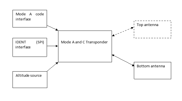 Figure 2: Mode A/C transponder interfaces
[Issue: CS-ACNS/4]
Appendix B – Background information on Mode S ELS
ED Decision 2022/008/R
This appendix provides background information on Elementary Surveillance (ELS) useful to understand ELS airborne surveillance system defined in the CS ACNS.D.ELS and its associated AMCs.
ETSO-C112d, Minimum Operational Performance Specification for SSR Mode S Transponders. (Based on EUROCAE ED-73E).
(i) ICAO Annex 10, Volume IV, Amd. 85, Aeronautical Communications (Surveillance Radar and Collision Avoidance Systems;)
(ii) ICAO Document 9871 Edition 2 (transponder register formats);
(iii) ICAO Document 8168-OPS/611 Volume I (Procedures for Air Navigation Services); and
(iv) ICAO Document Doc 4444-RAC/501 Procedures for Air Navigation Service, Air Traffic Management.
(i) ED-73E Minimum Operational Performance Specification for Secondary Surveillance Radar Mode S Transponders; and
(ii) ED-26 Minimum Performance Specification for Airborne Altitude Measurement and Coding Systems.
RTCA DO-181E.Minimum Operational Performance Specification for Air Traffic Control Radar Beacon System/Mode Select (ATCRBS/Mode S) Airborne Equipment
Airborne surveillance system description
This section describes the ELS system including transponder, interfaces, and antenna.
The following diagram represents the Mode S Transponder and its main functional interfaces.
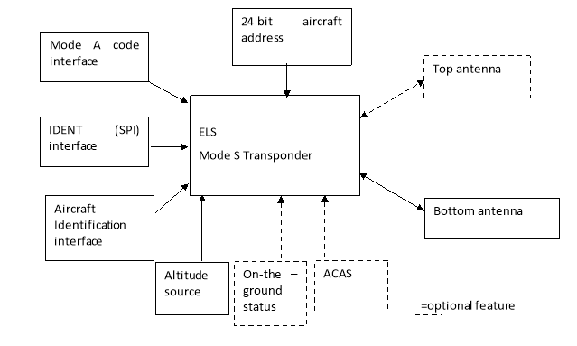
Figure 3: Mode S ELS transponder interfaces
(1) Acquisition of aircraft position by Mode S ELS radar
Aircraft entering the coverage of a Mode S radar is first acquired by All Call interrogations to which the transponder will reply if it is not on the ground. Therefore, it is important to test that the airborne surveillance system correctly takes into account the on-the-ground information. The on-the-ground status is also used by the ACAS systems to select aircraft which will be tracked.
During this acquisition phase the radar will acquire the Horizontal position and the 24-bit aircraft address corresponding to the aircraft technical address on the RF network.
The position and the aircraft address will be subsequently used to selectively interrogate the aircraft during the rest of its trajectory through the radar coverage.
Selective interrogations will be used:
(a) to update the horizontal position of the aircraft;
(b) to request the aircraft to not reply to the All Call interrogations specifically transmitted by the radar. This is known as lockout command;
(c) to request additional information such as Mode A code and altitude and
(d) to request further information to be downlinked from specific aircraft transponder registers such as the Aircraft Identification.
(2) Determination of the aircraft surveillance system capability
Ground surveillance system will need to establish the capabilities of the aircraft surveillance system to extract information only if it is available in the aircraft surveillance system. If this is not done, it could result in a situation where the aircraft would no longer reply to the interrogations used by the radar, and, therefore, the position of the aircraft could be lost. Hence, there is a need to have correct reporting of the aircraft surveillance system capability.
This process starts by determining whether the transponder is level 2 or above by checking the CA field of the Mode S All Call replies. The CA field is encoded with either 4,5,6,7 to indicate that the transponder is a level 2.
If the transponder is a level 2 or above transponder, the second step of the process is the verification of the data-link capability provided in register 1016, the ‘Data link capability report’. It contains different information about the data link capability of the airborne surveillance system
Elementary Surveillance System will use important information from this register, including:
(i) Aircraft Identification capability (bit 33 of register 1016) to determine the availability of the register containing the Aircraft Identification;
(ii) Surveillance Identifier code (bit 35 of register 1016) which indicates if SI protocol can be used to lockout the transponder; and
(iii) the Mode S Specific Services capability (bit 25 of register 1016) which indicates that Mode S specific services; including additional registers used for enhanced surveillance; are supported; and that the particular capability reports should be checked.
If the ‘Mode S Specific Services’ bit is set in register 1016, the availability of other registers will be checked by extracting register 1716.
(3) Extraction of Aircraft Identification using Mode S protocol
Aircraft equipped with Mode S having an aircraft identification feature transmits its Aircraft Identification as specified in Item 7 of the ICAO flight plan, or when no flight plan has been filed, the aircraft registration.
Aircraft Identification information will be obtained by Mode S radar by extracting the transponder register 2016 at the track initialisation.
The Aircraft Identification is variable when it changes from one flight to another flight. It is, therefore, possible that input errors may occur. Whenever it is observed on the ground situation display that the Aircraft Identification transmitted by a Mode S-equipped aircraft is different from that expected from the aircraft, the flight crew will be requested to confirm and, if necessary, re-enter the correct Aircraft Identification.
When Aircraft Identification is modified, the transponder will indicate this change for 18s in its selective replies. This is done using the Mode S Comm-B Broadcast protocol (ICAO Annex 10 Volume IV 3.1.2.6.11.4). The Mode S ground station will extract the Comm–B Broadcast message to obtain the new value of the Aircraft Identification.
(4) Extraction of Mode A code using Mode S protocol
Ground Mode S surveillance system will extract Mode A code at track initialisation.
If the Mode A code is modified, the transponder will indicate this change for 18s in its selective replies. This is done by raising an alert bit which is set for 18s after the change. Once this alert is detected, the Mode S ground stations will extract the new Mode A code.
It is, therefore important, that the change of the Mode A code happens on the active transponder which is announcing the change for 18s.
Note: ED-73E contains additional requirement requiring the announcement of a Mode A code change when a transponder becomes active. This is not necessarily available on older Mode S transponders in which it may be necessary to follow a specified procedure on installations with no common control interface. In some instances, a ground system workaround, consisting of periodically extracting the Mode A code, has also been implemented.
(5) ACAS Resolution Advisory (RA) report extraction
When a resolution advisory has been produced, the transponder announces the presence of a ‘RA report’ for the time that the RA is active until 18s after it has ceased. The Mode S ground stations will extract the register 3016 to obtain the information
(6) Summary of registers used for ELS
Register 1016 to obtain information on data link capability of the airborne surveillance system.
Register 1716 to obtain information on additional services available. For ELS, it is possible that register 1716 is empty (=0).
Register 2016 to obtain the Aircraft Identification.
Register 3016 to obtain the RA Report
(7) Information on Mode S replies used to support ELS
The following Mode S reply types are used to track the aircraft and obtain additional data:
DF11: Mode S All Call replies containing the 24-bit Aircraft Address and the CA field indicating whether the transponder is level 2 or greater and whether the aircraft is on the ground or airborne. DF11 can also be spontaneously transmitted as acquisition squitters. These replies are used for aircraft acquisition.
DF4: Short Mode S reply containing Altitude information.
DF5: Short Mode S reply containing the selected Mode A code.
DF20: Long Mode S reply containing the Altitude information and the content of the transponder register requested.
DF21: Long Mode S reply containing the Mode A code and the content of the transponder register requested.
[Issue: CS-ACNS/4]
Appendix C – Background information on Mode S EHS
ED Decision 2022/008/R
This appendix provides background information on Enhanced Surveillance (EHS) useful to understand EHS airborne surveillance system defined in the CS ACNS.D.EHS and its associated AMCs.
ETSO-C112d, Minimum Operational Performance Specification for SSR Mode S Transponders. (Based on EUROCAE ED-73E).
(i) The Concept of Operations - Mode S in Europe, document SUR.ET2.ST02.1000-CNP-01-00, Edition 2, Nov 1996:
(ii) Operational Hazard Assessment of Elementary and Enhanced Surveillance, Edition 1.1, EATMP Infocentre Reference: 04/04/07-01, 07.04.2004; and
(iii) Preliminary System Safety Analysis for the Controller Access Parameter service delivered by Mode S Enhanced Surveillance, Edition 1.1, EATMP Infocentre Reference: 04/04/07-02, 07.04.2004
(i) ICAO Annex 10, Volume IV, Amd. 85, Aeronautical Communications (Surveillance Radar and Collision Avoidance Systems; )
(ii) ICAO Document 9871 Edition 2;
(iii) ICAO Document 8168-OPS/611 Volume I (Procedures for Air Navigation Services); and
(iv) ICAO Document Doc 4444-RAC/501 Procedures for Air Navigation Service, Air Traffic Management.
(i) ED-73E Minimum Operational Performance Specification for Secondary Surveillance Radar Mode S Transponders;
(ii) ED-26 Minimum Performance Specification for Airborne Altitude Measurement and Coding Systems; and
(iii) ED-12C Software Considerations in Airborne Systems and Equipment Certification.
DO-181E Minimum Operational Performance Specification for Air Traffic Control Radar Beacon System/ Mode Select (ATCRBS/Mode S) Airborne Equipment.
(c) Background information
(1) Airborne surveillance system description
This section describes the EHS system including transponder, interfaces, and antenna.
The following diagram represents the Mode S Transponder, and its main functional interfaces. It is to be noted that different interfaces coming from different parts of the avionics may need to be connected to the transponder to support EHS.
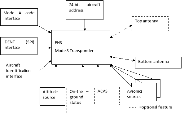
Figure 4: Mode S EHS transponder interfaces
(2) Registers used to support EHS capability
In addition to the registers already used for ELS capability establishment, the EHS capability of the aircraft will be established using register 1716 and 1D16.
Register 1716 will indicate which other registers (e.g. 4016,5016,6016) are currently supported by the airborne surveillance system.
Ground systems could also use register 1816 to 1C16, if available, to determine which registers are installed if those register are not included in register 1716.
Register 1D16 is used to determine if Dataflash specific MSP is installed. Dataflash is an application allowing the transmission of registers to the ground only when they have changed, and, therefore, removing the need for periodic extraction of registers. Dataflash is not expected to be installed, however, some Mode S ground stations have been developed to take benefit of the dataflash application when available on aircraft.
Mode S ground stations can also use Mode S sub network version to filter old systems not correctly supporting EHS.
Example of a basic list of registers and parameters to use to support the declaration of registers and parameters supported by an EHS installation is provided in Table 2 below.
Table 2 - Example of basic list of EHS registers and parameters
|
Register number |
Assignment |
Capability reporting in register 1816 to 1C16 |
parameters |
EHS req |
|
4016 |
Selected vertical intention |
Reg. 1916 |
MCP/FCU Selected Altitude |
Yes |
|
FMS Selected Altitude |
No |
|||
|
Barometric Pressure Setting |
Yes |
|||
|
MCP/FCU Mode bits |
No |
|||
|
Target altitude source bits |
No |
|||
|
5016 |
Track and turn report |
Reg. 1916 |
Roll Angle |
Yes |
|
True Track angle |
Yes |
|||
|
Ground speed |
Yes |
|||
|
Track Angle Rate |
Yes |
|||
|
True Airspeed |
Yes |
|||
|
6016 |
Heading and speed report |
Reg. 1916 |
Magnetic Heading |
Yes |
|
Indicated Airspeed |
Yes |
|||
|
Mach |
Yes |
|||
|
Barometric Altitude Rate |
Yes |
|||
|
Inertial Vertical Velocity |
Yes |
(3) Other data
Mode S ground stations can extract other data when available. It is, therefore, important that all data provided are verified.
The Table 3 provides more data to facilitate the declaration of other registers and parameters which may be supported and which may need to be added to the basic list provided above.
Table 3 - Example of extended list of Transponder registers and supported parameters
|
Register number |
Assignment |
Capability reporting in register 1816 to 1C16 |
parameters |
EHS req |
|
0B16 |
Air/air information 1 (aircraft state) |
Reg. 1816 |
True Air Speed |
No |
|
heading |
No |
|||
|
True track angle |
No |
|||
|
Ground speed |
No |
|||
|
0C16 |
Air/air information 2 (aircraft intent) |
Reg. 1816 |
Level Off Altitude |
No |
|
Next Course |
No |
|||
|
Time to Next Waypoint |
No |
|||
|
Vertical Velocity |
No |
|||
|
Roll Angle |
No |
|||
|
2116 |
Aircraft and airline registration markings |
Reg. 1816 |
Aircraft registration number |
No |
|
ICAO airline registration marking |
No |
|||
|
2216 |
Antenna positions |
Reg. 1816 |
|
No |
|
2516 |
Aircraft type |
Reg. 1816 |
|
No |
|
4116 |
Next waypoint identifier |
Reg. 1916 |
- |
No |
|
4216 |
Next waypoint position |
Reg. 1916 |
Waypoint latitude |
No |
|
Waypoint Longitude |
No |
|||
|
Waypoint Crossing Altitude |
No |
|||
|
4316 |
Next waypoint information |
Reg. 1916 |
Bearing to waypoint |
No |
|
Time To Go |
No |
|||
|
Distance To Go |
No |
|||
|
4416 |
Meteorological routine air report |
Reg. 1916 |
Wind Speed and Direction |
No |
|
Average Static Pressure |
No |
|||
|
Turbulence |
No |
|||
|
Humidity |
No |
|||
|
4516 |
Meteorological hazard report |
Reg. 1916 |
Turbulence |
No |
|
Wind Shear |
No |
|||
|
Microburst |
No |
|||
|
Icing |
No |
|||
|
Wake vortex |
No |
|||
|
Static Air temperature |
No |
|||
|
Average Static Pressure |
No |
|||
|
Radio Height |
No |
|||
|
4816 |
VHF channel report |
Reg. 1916 |
VHF1 |
No |
|
VHF2 |
No |
|||
|
VHF3 |
No |
|||
|
5116 |
Position report coarse |
Reg. 1916 |
Latitude and Longitude and Pressure altitude |
No |
|
5216 |
Position report fine |
Reg. 1916 |
Latitude fine and Longitude Fine and Pressure altitude or GNSS Height |
No |
|
5316 |
Air-referenced state vector |
Reg. 1916 |
Magnetic Heading |
No |
|
Indicated Airspeed |
No |
|||
|
Mach Number |
No |
|||
|
True Airspeed |
No |
|||
|
Altitude Rate |
No |
|||
|
5416 |
Waypoint 1 |
Reg. 1916 |
- |
No |
|
5516 |
Waypoint 2 |
Reg. 1916 |
- |
No |
|
5616 |
Waypoint 3 |
Reg. 1916 |
- |
No |
|
E316 |
Transponder type/part number |
Reg. 1C16 |
- |
No |
|
E416 |
Transponder software revision number |
Reg. 1C16 |
- |
No |
|
E516 |
ACAS unit part number |
Reg. 1C16 |
- |
No |
|
E616 |
ACAS unit software revision number |
Reg. 1C16 |
- |
No |
|
F116 |
Military applications |
Reg. 1C16 |
- |
No |
|
F216 |
Military applications |
Reg. 1C16 |
- |
No |
Note 1: When different fields are defined with their own status, each field will be listed in the table. In this case, it is possible to indicate the provision of the associated parameter by checking the value of the associated status bit.
Note 2: For more information about the content of the registers see Doc 9871 Edition 2 or above.
Note 3: It is recommended to provide registers E316, E416, E516 and E616.
(d) Existing installed transponders
A number of service bulletins have been issued to rectify some observed deficiencies and have already been addressed by the equipment manufacturers Therefore, the installed transponders should have all published corrective transponder equipment service bulletins (SB) relating to the correct operation of the elementary functionality embodied.
[Issue: CS-ACNS/4]
Appendix D – Differences between CS ACNS.D.ELS and JAA TGL 13 Rev1
ED Decision 2022/008/R
To demonstrate compliance with the CS-ACNS elementary surveillance requirements, the following additional points need to be addressed for aircraft previously compliant with Joint Aviation Authorities (JAA) Temporary Guidance Leaflet (TGL) 13 Revision 1:
(a) verification that the aircraft identifications sent in ‘extended squitter’ messages and in the Mode S replies are identical (see CS ACNS.D.ELS.015(b)(2));
(b) verification that the pressure altitudes provided in ‘extended squitter’ messages and in Mode S replies are identical if the installation sends ‘extended squitter’ messages (see CS ACNS.D.ELS.015(b)(2)); and
(c) other parameters provided by the airborne surveillance system are verified as correct and are correctly indicated, as available (see CS ACNS.D.ELS.015(b)(1)).
Note. The tests of the other parameters transmitted by the system allow certification of aircraft not subject to full EHS mandate but capable of transmitting some of the parameters which can be used by the operational systems.
[Issue: CS-ACNS/4]
Appendix E – Differences between CS ACNS.D.EHS and EASA AMC 20-13
ED Decision 2022/008/R
To demonstrate compliance with the CS ACNS enhanced surveillance requirements, the following additional points need to be addressed for aircraft previously compliant with EASA AMC 20-13:
(a) all transmitted parameters are correct and are correctly indicated, as available (see CS ACNS.D.EHS.015(c)); and
(b) barometric pressure setting is provided (see CS ACNS.D.EHS.015(a)(8) and (c)).
[Issue: CS-ACNS/4]
Appendix F – Example of Flight Manual Supplement for ELS/EHS
ED Decision 2013/031/R
This Flight Manual is EASA approved under Approval Number P-EASA.xxxxx
Flight Manual [or POH as appropriate] Reference _______
(Company Name)
FLIGHT MANUAL SUPPLEMENT
Aircraft Model: ______
Serial Number: ___
SSR MODE S Elementary/Enhanced Surveillance
Modification Number __________
|
The limitations and information contained herein either supplement or, in the case of conflict, override those in the flight manual. |
GENERAL
The installed transponder system is able to respond to interrogations in Modes A, C and S and is fully compliant with the requirements of CS ACNS.D.ELS/EHS (Mode S Elementary/Enhanced Surveillance). A detailed description of the transponder operation can be found in the ___________________, P/N _________________, Rev. ____ or subsequent revisions.
LIMITATIONS
None
EMERGENCY PROCEDURES
No change to Approved Aircraft Flight Manual
NORMAL/ ABNORMAL PROCEDURES
Normal/Abnormal transponder operating procedures are described in the _______________, P/N ___________________, Rev. _____ or subsequent revisions.
The procedure to change Aircraft Identification in flight is described in ________________________.
PERFORMANCE
No change to Approved Aircraft Flight Manual.
|
To be inserted in the flight manual and record sheet amended accordingly. |
|
Page (__) of (__)
|
Authority/DOA Approval:____________________Date:___________ |
|
Issue:_______ |
Signature:___________________________________ |
Appendix G – Example of Flight Manual Supplement for ADS-B out
ED Decision 2013/031/R
(Aircraft TypeFlight) Manual [or POH as appropriate] Reference (XXXX)
(Company Name)
FLIGHT MANUAL SUPPLEMENT (1) ISSUE (1)
Aircraft Model: ______
Serial Number: ___
ADS-B Out
Modification Number _____
ADDITIONAL LIMITATIONS AND INFORMATION
|
The limitations and information contained herein either supplement or, in the case of conflict, override those in the flight manual. |
GENERAL
The installed ADS-B out system is fully compliant with the requirements of CS ACNS.D.ADSB (1090 MHz Extended Squitter ADS-B Out). A detailed description of the system operation can be found in the ___________________, P/N _________________, Rev. ____ or subsequent revisions.
LIMITATIONS
None
EMERGENCY PROCEDURES
No change to Approved Aircraft Flight Manual
NORMAL/ ABNORMAL PROCEDURES
Normal/Abnormal operating procedures are described in the _______________, P/N ___________________, Rev. _____ or subsequent revisions.
The procedure to change Aircraft Identification in flight is described in ________________________.
PERFORMANCE
No change to Approved Aircraft Flight Manual
|
To be inserted in the flight manual and record sheet amended accordingly. |
|
Page (__) of (__)
|
Authority/DOA Approval:____________________Date:___________ |
|
Issue:_______ |
Signature:___________________________________ |
Appendix H – Guidance on 1090-MHz extended squitter ADS-B Out
ED Decision 2022/008/R
Part 1 – ADS-B Out Data Parameters (AMC ACNS.D.ADSB.020(a))
Part 1 of this Appendix provides guidance to the aircraft integrator on the minimum ADS-B Out surveillance data requirements (Table 5 and associated Definitions).
In addition, guidance is given for the overall understanding of the ADS-B Out system, in support of equipment configuration and ADS-B Out data parameter testing, as appropriate. This includes the presentation of data encodings related to the so-called BDS registers (Table 4), as extracted from ED‑102A. The content of the various BDS registers are loaded into the 56-bit ADS-B message (ME) field of the Mode S Downlink Format 17 (DF17, bits 33-88), in line with their respective transmission rates.
Table 5 below makes reference to the BDS registers that contain the various ADS-B Out data parameters. When Table 5 states Same source as for Mode S replies, reference is made to the requirement that the content of ADS-B broadcasts and Mode S replies that carry the same information need to come from the same source (CS ACNS.D.ADSB.025(b)).
The reference to the BDS registers is provided in order to facilitate a detailed understanding and traceability of ADS-B Out requirements at ADS-B transmit unit level, also in support of integration testing, as appropriate.
The relationship between the BDS registers and the ADS-B message Type Codes (first 5 bits in the 56‑bit ADS-B message field) is thereby as shown in Table 4. The Type Code is used to differentiate between ADS-B message types (i.e. BDS registers). In addition, for Airborne and Surface Position Messages, the Type Code is used to encode the horizontal position integrity containment bounds (NIC). The Subtype Code is used to further differentiate between ADS-B messages of a certain type (e.g. Operational Status Message).
A number of service bulletins have been issued to rectify some observed deficiencies and have already been addressed by the equipment manufacturers. Therefore, the installed transponders should have all published corrective transponder equipment service bulletins (SB) relating to the correct operation of the ADS-B functionality embodied.
Table 4: BDS Register Overview
|
BDS Register |
Type Code(s) |
Subtype Code |
|
0516 – Airborne Position Message |
0, 9-18, 20-22 |
n/a |
|
0616 – Surface Position Message |
0, 5-8 |
n/a |
|
0816 - Aircraft Identification and Category Message |
1, 2, 3 or 4 |
n/a |
|
0916 - Airborne Velocity Message Velocity over Ground (Normal/Supersonic) |
19 |
1+2 |
|
6116 - Aircraft Status Message Emergency Status and Mode A Code |
28 |
1 |
|
6116 - Aircraft Status Message ACAS RA Broadcast |
28 |
2 |
|
6216 - Target State and Status Message |
29 |
1 |
|
6516 – Aircraft Operational Status Message While Airborne |
31 |
0 |
|
6516 – Aircraft Operational Status Message On the Surface |
31 |
1 |
Note: Although BDS registers 0716 and 0A16 are not conveying ADS-B data items their implementation is needed to complement the ADS-B protocol.
Table 5: Minimum ADS-B Out Surveillance Data Transmission Requirements
|
Item |
Parameter |
Requirements |
BDS Register |
Remarks |
|
1 |
Aircraft Identification |
See Definition 1 |
0816
|
Same source as for Mode S replies |
|
2 |
Mode A Code |
See Definition 2 |
6116 |
Same source as for Mode S replies Broadcast suppressed for conspicuity code ‘1000’ |
|
3 |
ICAO 24-bit aircraft address |
Transmit ICAO 24-bit aircraft address |
All BDS (AA field of DF17, bits 9-32) |
Unique ICAO 24 bit aircraft address needs to be assigned by the responsible authority |
|
4a |
Airborne Horizontal Position – Latitude and Longitude |
See Definition 3 |
0516 |
|
|
4b |
Airborne Horizontal Position Quality: NIC |
See Definition 4 and 5 |
0516 Type Codes |
Incl. NIC Supplements A (6516) and B (0516) |
|
4c |
Horizontal Position Quality: NACp |
See Definition 4 and 6 |
6216 and 6516 |
|
|
4d |
Horizontal Position Quality: SIL |
See Definition 4 and 7 |
6216 and 6516 |
Incl. SIL Supplement. |
|
4e |
Horizontal Position Quality: SDA |
See Definition 4 and 8 |
6516 |
|
|
5 |
Pressure Altitude |
See Definition 9 |
0516 |
Same source as for Mode S replies Data associated with ‘NICbaro’ integrity indicator |
|
6 |
Special Position Identification (SPI) |
Setting as per ED-73E §2.5 |
0516 |
Same source as for Mode S replies |
|
7a |
Emergency Status |
See Definition 10 |
6116 (subtype 1) |
Same source as for Mode S replies (where defined for SSR) |
|
7b |
Emergency Indication |
Setting as per ED-73E §2.5 |
0516 |
Same source as for Mode S replies |
|
8 |
1090 ES Version Number |
To be set to 2 for ED-102A/DO-260B systems. |
6516 |
Value is fixed at the time the ADS-B transmit unit is manufactured. |
|
|
||||
|
9a |
Airborne Horizontal Velocity (Ground Speed) - east/west and north/south |
See Definition 11 |
0916 (subtypes 1and2) |
Same source as for SSR EHS replies |
|
9b |
Horizontal Velocity Quality: NACv |
See Definition 12 |
0916 (airborne) and 6516 (subtype 1, surface) |
|
|
10 |
Emitter Category |
See Definition 13 |
0816 |
|
|
11 |
Vertical Rate |
See Definition 14 |
0916 (subtypes 1and2) |
Selected source is indicated in 0916 source indication |
|
|
||||
|
12a |
Surface Horizontal Position – Latitude and Longitude |
Source see AMC ACNS.D.ADSB.070 See Definition 3 |
0616 |
Quality indicators NACp, SIL, SDA: same encodings as for airborne horizontal position |
|
12b |
Surface Horizontal Position Quality: NIC |
See Definition 15 |
0616 Type Codes |
Incl. NIC Supplements A and C (both 6516) |
|
13 |
Heading/Ground Track |
See Definition 16 |
0616 |
Heading preferred source |
|
14 |
Movement (surface ground speed) |
See Definitions 11 and 12 |
0616 |
NACv: same as for airborne ground velocity (see 9b) |
|
15 |
Length/width of Aircraft |
See Definition 17 |
6516 (subtype 1) |
|
|
16 |
GPS Antenna Offset |
See Definition 18 |
6516 (subtype 1) |
Lateral and longitudinal |
|
|
||||
|
17a |
Geometric Altitude |
See Definition 19 |
0916 (0516) |
In 0916 reported as difference from Pressure Altitude |
|
17b |
Geometric Altitude Quality: GVA |
See Definition 20 |
6516 (subtype 0) |
|
Definition 1: Aircraft Identification Data Sources
Aircraft Identification is provided to the ADS-B transmit unit so that the information is identical to the filed ICAO flight plan. This information may be provided from, amongst others:
A flight management system; or
A pilot control panel; or
For aircraft, which always operate with the same aircraft identification (e.g. using registration as the aircraft identification), it may be programmed into equipment at installation.
In case no ICAO flight plan is filed, the Aircraft Registration is provided to the ADS-B transmit unit.
Definition 2: Mode A Code
Refer to AMC1 ACNS.D.ELS.015 for general guidance.
When the ADS-B transmit unit receives a Mode A Code containing the Mode S conspicuity code (1000), the broadcast of Mode A code information is stopped.
Note: The broadcast of the Mode A Code is provided as a transitional feature, e.g. to aid operation of legacy ATC automation systems that use Mode A Code for Flight Plan correlation. Entry of the Mode A Code of 1000 will disable the transmission of the Mode A Code, and, hence, reduce the overall 1090 ES transmission rate.
Definition 3: Horizontal Position Information
The Mode S Extended Squitter position format uses the Compact Position Reporting (CPR) algorithm to encode latitude and longitude efficiently into messages. The resulting messages are compact in the sense that several higher order bits which are normally constant for long periods of time, are not transmitted in every message.
The CPR technique enables a receiving system to unambiguously determine the location of the aircraft, and, hence, reconstruct the original information provided by the source. If required for integration testing purposes, detailed guidance on the CPR algorithm is provided in ED‑102A/DO‑260B.
A horizontal position data source provides position information for both the airborne and surface horizontal position data formats (i.e. registers 0516 or 0616, respectively), accordingly encoded by the ADS-B transmit unit depending on the aircraft airborne/surface state.
Definition 4: Horizontal Position Quality – NIC and NACp
The encoding of the NIC and NACp horizontal position quality indicators should be directly derived from the corresponding integrity and accuracy information as being reported by the selected horizontal position source (refer also to CS ACNS.D.ADSB.025(c)).
In case a measurement integrity failure has been indicated by the selected horizontal position source (e.g. bit 11 of ARINC label 130 for ARINC 743A compliant sources), both the NIC and NACp quality indicators will be set to invalid (zero), regardless of the indicated integrity containment bound (e.g. HPL).
Definition 5: Airborne NIC Value
NIC is reported so that surveillance applications, such as by ATC or other aircraft, may determine whether the reported horizontal position has an acceptable level of measurement integrity for the intended use. (Note that the NIC parameter is closely associated with the SIL quality metric.)
The NIC (and SIL) values are associated with a possible failure condition of the position measurement function and the detection thereof. For most ADS-B applications, the NIC (and SIL) values are the key horizontal position quality metrics on which the horizontal position data is determined to be of sufficient quality for its intended use. The NIC value is encoded on the respective horizontal position integrity containment radius as provided by the source.
The NIC values, including the NIC Supplements values, are encoded for airborne position messages as follows (Rc is the horizontal position integrity containment bound, typically HPL/HIL for GNSS systems):
Table 6: Airborne NIC Encoding
|
NIC Value |
Radius of Containment (RC) |
Airborne |
||
|
Airborne Position TYPE Code |
NIC Supplement Codes |
|||
|
A |
B |
|||
|
0 |
RC unknown or RC ≥ 37 040 m (20 NM) |
0, 18 or 22 |
0 |
0 |
|
1 |
RC < 37 040 m (20 NM) |
17 |
0 |
0 |
|
2 |
RC < 14 816 m (8 NM) |
16 |
0 |
0 |
|
3 |
RC < 7 408 m (4 NM) |
16 |
1 |
1 |
|
4 |
RC < 3 704 m (2 NM) |
15 |
0 |
0 |
|
5 |
RC < 1 852 m (1 NM) |
14 |
0 |
0 |
|
6 |
RC < 1 111.2 m (0.6 NM) |
13 |
1 |
1 |
|
RC < 926 m (0.5 NM) |
13 |
0 |
0 |
|
|
RC < 555.6 m (0.3 NM) |
13 |
0 |
1 |
|
|
7 |
RC < 370.4 m (0.2 NM) |
12 |
0 |
0 |
|
8 |
RC < 185.2 m (0.1 NM) |
11 |
0 |
0 |
|
9 |
RC < 75 m |
11 |
1 |
1 |
|
10 |
RC < 25 m |
10 or 21 |
0 |
0 |
|
11 |
RC < 7.5 m |
9 or 20 |
0 |
0 |
Note: The minimum NIC values required for the ADS-B-RAD application can be found in Table 20, in Part 3 of Appendix H. They are met through the horizontal position source requirements defined in CS ACNS.D.ADSB.070.
Definition 6: NACp
NACp specifies the 95 % radial accuracy of the aircraft’s horizontal position information (latitude and longitude) derived from the position source’s accuracy output, typically the HFOM metric from GNSS based sources.
Whereas the NIC value is associated with a possible failure condition of the position measurement function, the NACp value describes the nominal performance of the measurement function in terms of horizontal position accuracy as provided by the source.
The NACp value is encoded as follows:
|
Coding |
95% Horizontal Accuracy Bound |
|
0 |
EPU ≥ 18 520 m (≥10 NM) |
|
1 |
EPU < 18 520 m (10 NM) |
|
2 |
EPU < 7 408 m (4 NM) |
|
3 |
EPU < 3 704 m (2 NM) |
|
4 |
EPU < 1852 m (1 NM) |
|
5 |
EPU < 926 m (0.5 NM) |
|
6 |
EPU < 555.6 m (0.3 NM) |
|
7 |
EPU < 185.2 m (0.1 NM) |
|
8 |
EPU < 92.6 m (0.05 NM) |
|
9 |
EPU < 30 m |
|
10 |
EPU < 10 m |
|
11 |
EPU < 3 m |
Note: The minimum NACp values required for the ADS-B-RAD application can be found in Table 20, in Part 3 of Appendix H. This value is met through the horizontal position source requirements defined in CS ACNS.D.ADSB.070.
The NACp encoding is the same for airborne position messages and surface position messages.
Definition 7: SIL
The encoding of the horizontal position source integrity level (SIL) is based on the probability of the reported horizontal position exceeding the radius of containment defined by the NIC, without alerting, assuming no avionics faults. The SIL value is set as follows:
|
SIL value |
Probability of Exceeding the NIC Containment Radius |
|
0 |
Unknown or > 1 10-3 per flight hour or per sample |
|
1 |
≤ 1 10-3 per flight hour or per sample |
|
2 |
≤ 1 10-5 per flight hour or per sample |
|
3 |
≤ 1 10-7 per flight hour or per sample |
Note: The minimum SIL value required for the ADS-B-RAD application can be found in Table 20, in Part 3 of Appendix H. This value is met through the horizontal position source requirements defined in CS ACNS.D.ADSB.070 (see also related AMC guidance).
Whereas SIL assumes that there are no system integrity failures, the SIL should consider the effects of a faulted signal-in-space.
For horizontal position sources compliant with CS ACNS.D.ADSB.070, the probability of exceeding a NIC radius of containment without alerting is based on a per hour rate. Hence, the SIL Supplement should be set to ‘zero’. If based on per sample, the SIL Supplement would be set to ‘one’.
The SIL encoding is the same for airborne position messages and surface position messages.
Definition 8: SDA
The encoding of the system design assurance level (SDA) is based on the failure condition that the entire ADS-B Out system, with respect to the horizontal position data and associated quality indicators, is designed to support.
The SDA value is encoded as follows:
|
SDA value |
Software & Hardware Design Assurance Level (see Note 1) |
Corresponding System Integrity Level |
|
0 |
N/A |
> 1X10⁻³ per flight hour or unknown (No Safety Effect) |
|
1 |
D |
≤ 1X10⁻³ per flight hour (Probable) |
|
2 |
C |
≤ 1X10⁻⁵ per flight hour (Remote) |
|
3 |
B |
≤ 1X10⁻⁷ per flight hour (Extremely Remote) |
Note 1: Software Design Assurance per EUROCAE ED-12C (RTCA DO-178C). Airborne Electronic Hardware Design Assurance per EUROCAE ED-80 (RTCA DO-254).
Note 2: In line with the ADS-B-RAD requirements, the minimum value required for the horizontal position source is SDA=2 ().
The SDA encoding is the same for airborne position messages and surface position messages.
Definition 9: Pressure Altitude Data Sources
Refer to AMC1 ACNS.D.ELS.015 for guidance.
The ADS-B NICbaro quality indicator is encoded as follows:
|
Coding |
Meaning |
|
0 |
The barometric altitude is based on a Gillham coded input that has not been cross-checked against another source of pressure altitude. |
|
1 |
The barometric altitude is either based on a Gillham code input that has been cross-checked against another source of pressure altitude and verified as being consistent, or is based on a non-Gillham coded source. |
Definition 10: Emergency Status
The provision of the ‘Emergency Status’ values that do not have a corresponding Mode A value (see CS ACNS.D.ELS.015(a)(6)), denoting the other emergency conditions defined in 6116, is optional. This applies to the decimal values 2, 3, 6 and 7 in Table 11.
Table 11: Emergency Status Encoding
|
Coding |
Meaning |
|
|
(Binary) |
(Decimal) |
|
|
000 |
0 |
No Emergency |
|
001 |
1 |
General Emergency |
|
010 |
2 |
Lifeguard/medical Emergency |
|
011 |
3 |
Minimum Fuel |
|
100 |
4 |
No Communications |
|
101 |
5 |
Unlawful Interference |
|
110 |
6 |
Downed Aircraft |
|
111 |
7 |
Reserved |
Definition 11: Horizontal Velocity (Ground Velocity)
The horizontal velocity provides the rate at which an aircraft changes its horizontal position with a clearly stated direction.
Velocity data sources provide ground velocity vector information for both the airborne and surface velocity data transmit formats, allowing for the transmission of east/west and north/south velocity information (0916), or velocity scalar (0616, movement) and possibly ground track information3 Refer to Definition 16. (0616), respectively.
In case of a failure of the provision of ground velocity data, the ADS-B transmit unit will broadcast airspeed (and heading) information instead (using subtypes 3 or 4 of register 0916.
Definition 12: Horizontal Velocity Quality Indicator NACv
The NACv is an estimate of the accuracy of the horizontal geometric velocity data.
The NACv value is encoded as follows:
|
Navigation Accuracy Category for Velocity - NACv |
||
|
Coding |
Horizontal Velocity Error (95%) |
|
|
(Binary) |
(Decimal) |
|
|
000 |
0 |
Unknown or > 10 m/s |
|
001 |
1 |
< 10 m/s |
|
010 |
2 |
< 3 m/s |
|
011 |
3 |
< 1 m/s |
|
100 |
4 |
< 0.3 m/s |
The NACv encoding is the same for airborne position messages and surface position messages.
Definition 13: Emitter Category
Emitter Category settings describe the size and performance of an aircraft, primarily expressed with respect to its maximum take-off weight.
The Emitter Category value is encoded as follows:
Table 13: Emitter Category Encoding
|
ADS-B Emitter Category Set “A” |
|
ADS-B Emitter Category Set “B” |
||
|
Coding |
Meaning |
|
Coding |
Meaning |
|
0 |
No ADS-B Emitter Category Information |
|
0 |
No ADS-B Emitter Category Information |
|
1 |
Light (< 7 031 kg (15 500 lbs)) |
|
1 |
Glider / Sailplane |
|
2 |
Small (7 031 to 34 019 kg (15 500 to 75 000 lbs)) |
|
2 |
Lighter-than-Air |
|
3 |
Large (34 019 to 136 078 kg (75 000 to 300 000 lbs)) |
|
3 |
Parachutist / Skydiver |
|
4 |
High-Vortex Large (aircraft such as B-757) |
|
4 |
Ultralight / hang-glider / paraglider |
|
5 |
Heavy (> 136 078 kg (300 000 lbs)) |
|
5 |
Reserved |
|
6 |
High Performance (> 49 m/s² (5g) acceleration and > 205 m/s (400 knots)) |
|
6 |
Unmanned Aerial Vehicle |
|
7 |
Rotorcraft |
|
7 |
Space / Trans-atmospheric vehicle |
|
|
|
|
|
|
|
|
|
|
|
|
|
ADS-B Emitter Category Set “C” |
|
ADS-B Emitter Category Set “D” |
||
|
Coding |
Meaning |
|
Coding |
Meaning |
|
0 |
No ADS-B Emitter Category Information |
|
0 |
No ADS-B Emitter Category Information |
|
1 |
Surface Vehicle - Emergency Vehicle |
|
1 - 7 |
Reserved |
|
2 |
Surface Vehicle - Service Vehicle |
|
|
|
|
3 |
Point Obstacle (includes tethered balloons) |
|
|
|
|
4 |
Cluster Obstacle |
|
|
|
|
5 |
Line Obstacle |
|
|
|
|
6 - 7 |
Reserved |
|
|
|
The ADS-B Emitter Category Sets A, B, C or D are identified by the Message Format TYPE Codes 4, 3, 2, and 1 respectively.
Note 1: A coding of ‘0’ within an Emitter Category Set is not allowed.
Note 2: The Emitter Category codes 1 to 5 in category set A are intended to advise other aircraft of the transmitting aircraft’s wake vortex characteristics, and not necessarily the transmitting aircraft’s actual maximum take-off weight. In case of doubt, the next higher aircraft category code should be used
Definition 14: Vertical Rate
Vertical Rate is either the barometric or geometric rate at which the aircraft is climbing or descending, measured in feet per minute. The vertical rate is typically generated by an air data computer or GNSS position source, or equipment which blends barometric vertical rate with inertial vertical rate and/or GNSS vertical rate.
As the geometric vertical rate can be readily derived from the ADS-B Out position source, it is classified as a minimum requirement rather than an (effectively Mode S Enhanced Surveillance) conditional requirement.
Definition 15: Surface NIC Value
The Surface NIC value, including the NIC Supplement A and C values, is encoded as follows:
Table 14: Surface NIC Encoding
|
NIC Value |
Radius of Containment |
Surface |
||
|
Surface Position TYPE Code |
NIC Supplement Codes |
|||
|
A |
C |
|||
|
0 |
RC unknown |
0, 8 |
0 |
0 |
|
6 |
RC < 1 111.2 m (0.6 NM) |
8 |
0 |
1 |
|
RC < 555.6 m (0.3 NM) |
8 |
1 |
0 |
|
|
7 |
RC < 370.4 m (0.2 NM) |
8 |
1 |
1 |
|
8 |
RC < 185.2 m (0.1 NM) |
7 |
0 |
0 |
|
9 |
RC < 75m |
7 |
1 |
0 |
|
10 |
RC < 25m |
6 |
0 |
0 |
|
11 |
RC < 7.5m |
5 |
0 |
0 |
Definition 16: Surface Heading/Ground Track
Aircraft Heading indicates the direction in which the nose of the aircraft is pointing. It should be used as the primary source and be expressed (in ME bit 54 in 6516) as either true north (‘0’, preferred) or magnetic north (‘1’).
If an approved heading source is not available (or failed during operation), the Ground Track angle information from the selected ground velocity data source will be used instead by the ADS-B transmit unit for the determination of the direction of the horizontal velocity vector.
If the position source ground track is used and inaccurate below a certain ground speed, and the position source does not inhibit output of the ground track at these slower speeds, the installer should ensure that the ADS-B transmit unit has the capability to invalidate the ground track when the GNSS ground speed falls below a threshold specified by the position source manufacturer (e.g. 3.6 m/s (7 knots)).
Definition 17: Aircraft Length and Width
Aircraft Length and Width settings describe the aircraft dimensions by the width and length of a rectangle that is aligned parallel to the aircraft’s heading. The aircraft’s length is to be measured along its axis of symmetry (i.e. from nose to tail). The aircraft’s width is to be measured from wing-tip to wing-tip.
The Aircraft Length and Width values are encoded as shown in Table 15 to be less than or equal to a respective upper bound length and width as expressed in the two right-side columns. The Length and Width Codes are based on a combined encoding of the actual length and width whereby the largest respective upper bound prevails. If the Aircraft or Vehicle is longer than 85 meters, or wider than 90 meters, then decimal Aircraft/Vehicle Length/Width Code 15 is used.
Table 15: Aircraft Length/Width Encoding
|
A/V - L/W Code |
Length Code |
Width Code |
Upper-Bound Length and Width |
|||
|
‘ME’ |
‘ME’ |
‘ME’ |
‘ME’ |
Length |
Width |
|
|
0 |
0 |
0 |
0 |
0 |
No Data or Unknown |
|
|
1 |
0 |
0 |
0 |
1 |
15 |
23 |
|
2 |
0 |
0 |
1 |
0 |
25 |
28.5 |
|
3 |
1 |
34 |
||||
|
4 |
0 |
1 |
0 |
0 |
35 |
33 |
|
5 |
1 |
38 |
||||
|
6 |
0 |
1 |
1 |
0 |
45 |
39.5 |
|
7 |
1 |
45 |
||||
|
8 |
1 |
0 |
0 |
0 |
55 |
45 |
|
9 |
1 |
52 |
||||
|
10 |
1 |
0 |
1 |
0 |
65 |
59.5 |
|
11 |
1 |
67 |
||||
|
12 |
1 |
1 |
0 |
0 |
75 |
72.5 |
|
13 |
1 |
80 |
||||
|
14 |
1 |
1 |
1 |
0 |
85 |
80 |
|
15 |
1 |
90 |
||||
Example: a powered glider with an overall length of 24 meters and wingspan of 50 meters would, normally, have a length code of ‘001’. However, since the wingspan exceeds 34 meters, it does not qualify for either Width subcategory of length category ‘001’. In line with its actual width, such an aircraft would be assigned a length code of ‘100’ and width code of ‘1’, meaning length less than 55 meters and width less than 52 meters.
Definition 18: GPS Antenna Offset (lateral and longitudinal)
GPS Antenna Offset information provides the position offset of the GNSS antenna used for the provision of horizontal position information.
Both a lateral distance of the GPS Antenna (from the longitudinal axis of the aircraft) and a longitudinal distance of the GPS Antenna (from the nose of the aircraft) are provided.
The accuracy of the information should be better than 2 meters, consistent with the data resolution.
The lateral and longitudinal GPS Antenna Offset values are encoded as follows:
Table 16: Lateral Axis GPS Antenna Offset Encoding
|
‘ME’ Bit (Message Bit) |
Upper Bound of the GPS Antenna Offset Along Lateral (Pitch) Axis Left or Right of Longitudinal (Roll) Axis |
|||
|
33 (65) |
34 (66) |
35 (67) |
||
|
0 = left 1 = right |
Encoding |
|||
|
Bit 1 |
Bit 0 |
Direction |
(meters) |
|
|
0 |
0 |
0 |
LEFT |
NO DATA |
|
0 |
1 |
2 |
||
|
1 |
0 |
4 |
||
|
1 |
1 |
6 |
||
|
1 |
0 |
0 |
RIGHT |
0 |
|
0 |
1 |
2 |
||
|
1 |
0 |
4 |
||
|
1 |
1 |
6 |
||
Supplementary Notes
Maximum distance left or right of aircraft longitudinal (roll) axis is 6 meters or 19.685 feet. If the distance is greater than 6 meters, then the encoding should be set to 6 meters.
The No Data case is indicated by encoding of 000 as above, while the ZERO offset case is represented by encoding of 100 as above.
The rounding should be performed to half of the resolution of the GPS antenna offset information, i.e. +/- 1 meter.
Table 17: Longitudinal Axis GPS Antenna Offset Encoding
|
‘ME’ Bit (Message Bit) |
Upper Bound of the GPS Antenna Offset Along Longitudinal (Roll) Axis Aft From Aircraft Nose |
||||
|
36 (68) |
37 (69) |
38 (70) |
39 (71) |
40 (72) |
|
|
Encoding |
|||||
|
Bit 4 |
Bit 3 |
Bit 2 |
Bit 1 |
Bit 0 |
(meters) |
|
0 |
0 |
0 |
0 |
0 |
NO DATA |
|
0 |
0 |
0 |
0 |
1 |
Position Offset Applied by Sensor (see also Notes) |
|
0 |
0 |
0 |
1 |
0 |
2 |
|
0 |
0 |
0 |
1 |
1 |
4 |
|
0 |
0 |
1 |
0 |
0 |
6 |
|
* |
* |
* |
* |
* |
*** |
|
1 |
1 |
1 |
1 |
1 |
60 |
Supplementary Notes:
If the distance is greater than 60 meters, the encoding should be set to 60 meters.
Position Offset Applied by the Sensor applies to future cases where the antenna offset is compensated by the horizontal position source to the centre of the rectangle describing the aircraft’s length and width (refer to Definition 17).
The encoding of the values from decimal ‘2’ (only bit 1 one set to ‘1’) to ‘31’ (all five bits set to ‘1’) is as follows: encoded binary value = offset [m]) / 2 + 1 (e.g. an offset of 4 meters leads to a binary value of (4/2 + 1 = 3), i.e. Bits 0-1 equal ‘1’ and Bits 2-4 equal ‘0’).
Definition 19: Geometric Altitude
The geometric altitude is a measure of the aircraft’s height above a geometric reference and is provided by a GNSS-based position source.
Both within 0516 and 0916, Geometric Altitude is provided as height above ellipsoid (HAE) in accordance with the WGS 84 coordinate system (AMC1 ACNS.D.ADSB.085(b)).
Definition 20: Geometric altitude quality indicator information (GVA)
The GVA parameter expresses the actual performance of the geometric altitude data source as valid at the time of applicability of the measurement.
The GVA value is encoded as follows:
|
GVA Encoding (decimal) |
95% Accuracy (meters) |
|
0 |
Unknown or > 150 meters |
|
1 |
≤ 150 meters |
|
2 |
< 45 meters |
|
3 |
Reserved |
Part 2 – ADS-B Out Surveillance Data Parameters (AMC1 ACNS.D.ADSB.020(b))
Table 19 below makes reference to the BDS register(s) that contain the various ADS-B Out surveillance data parameters. When Table 19 states Same source as for Mode S replies, reference is made to the requirement that the content of ADS-B broadcasts and Mode S replies that carry the same information and need to come from the same source (CS ACNS.D.ADSB.025(b)).
Guidance on the content of the various BDS registers and their relationship with the ADS-B message Type Codes is provided in Table 4 in part 1 of Appendix H.
Table 19: ADS-B-ADD Surveillance Data Transmission Requirements
|
Item |
Parameter |
Requirements |
BDS Register |
Remarks |
|
1 |
Selected Altitude |
See Definition 21. |
6216 |
Same source as for Mode S replies |
|
2 |
Barometric Pressure Setting |
6216 |
||
|
3a |
ACAS Operational |
See Definition 22. |
6216 and 6516 |
|
|
3b |
Resolution Advisory (RA) |
6116 (subtype 2) |
Definition 21: Selected Altitude/Barometric Pressure Setting
Refer to AMC1 ACNS.D.EHS.015(c)(1) and (c)(3) for detailed guidance.
Definition 22: ACAS Operational /Resolution Advisory (RA)
Refer to AMC1 ACNS.D.ELS.015(f) for detailed guidance.
The data is populated from ACAS II systems if installed on the aircraft. Both parameters should be preset to ‘zero’ if an ACAS II system is not installed (refer to ADS-B transmit unit manufacturer instructions).
Part 3 – ADS-B Out Minimum Horizontal Position and Velocity Data Requirements
Table 20 provides a summary of the minimum horizontal position data requirements as specified in the defining ADS-B-RAD Safety and Performance Requirements/Interoperability document (ED-161).
Table 20: Minimum Horizontal Position and Velocity Data Quality Requirements
|
Quality Parameter |
Requirement |
|
Position Accuracy (NACp) |
NACp<=185.2 m (0.1NM) (i.e. NACp>=7) for both 3 NM and 5 NM separation |
|
Position Integrity Containment Radius (NIC) |
3 NM Sep: NIC<=1 111.2 m (0.6 NM) (i.e. NIC>=6) 5 NM Sep: NIC<=1 852 m (1 NM) (i.e. NIC>=5) |
|
Source Integrity Level (SIL) |
SIL=3: 10-7/flight-hour |
|
System Design Assurance (SDA) |
SDA=2: 10-5/flight-hour - allowable probability level REMOTE (MAJOR failure condition, LEVEL C software and design assurance level) |
|
Velocity Accuracy (NACv) |
NACv<=10 m/s (i.e. NACv>=1) |
Note 1: The requirement of NACp<=0.1NM in support of 3NM separation is based on the arguments produced in Annex B to ED-161 (ADS-B-RAD Safety and Performance Requirements/Interoperability Requirements Document).
Note 2: The SDA encoding of ‘2’ (10-5/fight-hour) applies to individual components of the ADS-B Out system, i.e. 10-5/fight-hour for the ADS-B transmit unit and 10-5/flight-hour for the horizontal position and velocity source.
Note 3: ADS-B transmit units interfaced with a GNSS position source that is compliant with CS ACNS.D.ADSB.070 (and the related AMC guidance) should preset the SIL Supplement to ‘zero’.
Note 4: If set as fixed value, NACv should be always ‘one’. For quality indications that are dynamically provided by the velocity source, NACv should be ‘one’ or ‘two’. There is currently no established guidance on establishing a NACv performance of ‘three’ or better.
This should be verified through appropriate tests, as follows. With respect to NIC and NACp testing, the ADS-B Out system installer should check for satellite shielding and masking effects if the stated performance is not achieved.
(a) Airborne & Surface NIC:
During testing under nominal GNSS satellite constellation and visibility conditions, the transmitted NIC value should be a minimum of ‘six’.
(b) NACp:
During testing under nominal GNSS satellite constellation and visibility conditions, the transmitted NACp value should be a minimum of ‘eight’
In order to validate the correctness of the transmitted horizontal position, the aircraft should be positioned on a known location.
(c) SIL:
SIL is typically a static (unchanging) value and may be set at the time of installation if a single type of position source is integrated with the ADS-B transmit unit. SIL should be set based on design data from the position source equipment manufacturer. Installations which derive SIL from GNSS position sources compliant with CS ACNS.D.ADSB.070 should set the SIL to ‘three’.
ADS-B transmit units interfaced with a GNSS position source that is compliant with CS ACNS.D.ADSB.070 (and the related AMC guidance) should pre-set the SIL Supplement to ‘zero’.
(d) NACv:
If set as fixed value, NACv should be always ‘one’. For quality indications that are dynamically provided by the velocity source, NACv should be ‘one’ or ‘two’.
It is noted that there is currently no established guidance on establishing a NACv performance of ‘three’ or better.
Part 4 – ADS-B Out Integrity and Continuity Requirements
CS ACNS.D.ADSB.100 and CS ACNS.D.ADSB.105 summarise, per data parameter, the integrity and continuity probability levels applicable to the ADS-B Out system.
In the first place, the ADS-B Out System installed in the aircraft needs to deliver data that satisfy the ADS-B-RAD airborne domain system safety and performance requirements in line with Section 3.4 of the ADS-B-RAD Safety and Performance Requirements/Interoperability standard ED-161.
As, for the purpose of framing the ADS-B-RAD operational safety assessment, the ADS-B-RAD airborne domain only comprises the horizontal position data source and the ADS-B transmit unit, including the interconnecting avionics, the data sources providing surveillance information other than horizontal position and velocity are assumed to operate as within today’s SSR environment. Hence, in line with CS ACNS.D.ADSB.080, the related Mode S Elementary and Enhanced Surveillance requirements apply.
It is noted that the respective Mode S Elementary and Enhanced Surveillance requirements have to be understood within their given context, in particular taking into account applicable procedural mitigation means (e.g. as currently performed by means of the ICAO required controller-pilot verification procedure for pressure altitude reporting).
The ADS-B Out data parameters other than the ones addressed in the preceding paragraphs, need to satisfy comparable ADS-B-RAD requirements.
The specified integrity levels are required to adequately protect against the corruption of ADS-B Out surveillance data causing false or misleading information to be transmitted.
Although the direct effects to an aircraft of an ADS-B Out failure may be minor, the ADS-B Out information will be used by ATC and other ADS-B equipped aircraft, thus provisions that would allow for a reduction in failure probabilities and design assurance level, do not apply to the ADS-B Out system.
Part 5 – GNSS Position and Velocity Source Qualification
This part 5 of Appendix H provides guidance to GNSS equipment manufacturers on how to establish a qualification for these ADS-B specific requirements, i.e. beyond the demonstration of compliance to ETSO requirements. In the following, as appropriate, reference is made to the respective:
— ETSO material: ETSO-C129a (JTSO-C129a), ETSO-C196a, ETSO-C145()/146()
— EUROCAE/RTCA MOPS material: ED-72A, DO-208, DO-229D, DO-316 as well as DO-235B; and
— FAA AC material (AC 20-138C).
Note: ETSO-C145 refers to RTCA DO-229A, ETSO-C146 refers to RTCA DO-229B, ETSO-C145c/146c refers to RTCA DO-229D, and ETSO-C145()/146() refers to any of those revisions.
In addition to the ETSO minimum requirements, the requirements of this part need to be demonstrated unless this has been demonstrated as a declared non-ETSO function. It is expected that the required compliance demonstration is supplied by the position and velocity source manufacturer through a Declaration of Design and Performance (DDP), or an equivalent document.
(a) Horizontal Position Integrity (HPL)
Horizontal Position Integrity – AMC1 ACNS.D.ADSB.070(a)(1) and (a)(2)(ii).
Applicability: ETSO-C129a (JTSO-C129a)
GNSS equipment manufacturers should provide substantiation data showing that the equipment outputs latitude and longitude information that is referenced to the WGS-84 coordinate system.
GNSS equipment manufacturers should provide substantiation data showing that the equipment outputs a 10-7/hr Horizontal Protection Limit (HPL, or equivalent) based on the RAIM algorithm meeting the ETSO-C129a (JTSO-C129a) Class A1, A2, B1, B2, C1, or C2 RAIM requirements.
Applicability: ETSO-C145()/146()
SBAS equipment certified under any revision of ETSO-C145 or ETSO-C146 is required to have several modes of operation depending on the availability of augmentation. For example, when operating in an augmented mode intended for LPV approach guidance, the position source may determine HPL based on a lateral error versus a horizontal error and an exposure time based on the duration of the approach versus flight hour (refer to Appendix J to RTCA DO229D for details).
If the position source outputs the HPL on lateral error and approach exposure time, it is possible that the ADS-B transmit function would need to inflate the HPL by 3% in approach modes to ensure the integrity is appropriately bounded.
GNSS equipment manufacturers should provide information data to determine if the integrity output needs to be scaled (i.e., by applying an inflation factor). The same considerations apply to GBAS differentially-corrected position sources when in approach mode.
Integrity Fault – Time to Alert – AMC1 ACNS.D.ADSB.070(a)(1) and (a)(2)(iii).
Applicability: ETSO-C129a (JTSO-C129a)
For the horizontal position sources compliant with AMC ACNS.D.ADSB.070, it should to be demonstrated, that a non-isolated GNSS satellite fault detected by the position source is properly passed to the ADS-B transmit unit within the allowable time to alert of 10 seconds, at any time.
With reference to the mode-dependent time to alert in Table 3-5 of EUROCAE ED-72A, Section 3.2.1 (Table 2-1 of RTCA DO-208 Section 2.2.1.13.1), GNSS equipment manufacturers should provide information describing the equipment integrity fault output latency, along with interface instructions and/or any limitations for meeting the 10-second latency requirement of AMC1 ACNS.D.ADSB.070(a)(1) and (a)(2)(iii).
Note 1: The latency of reporting nominal ADS-B ‘Quality Indicator’ changes, such as in response to changing GNSS satellite constellations or due to switching between position sources, is bounded by AMC1 ACNS.D.ADSB.070(a)(2)(iii) as well.
Note 2: ED-72A allows a provision to extend the Time to Alarm up to 30 seconds during en route phases of flight while for terminal and Non-Precision Approach the 10-second limit is applicable. For ADS-B Out, a time to alert of 10 seconds applies to any phases of flight.
Mode Output – AMC1 ACNS.D.ADSB.070(a)(1) and (a)(3)
Applicability: ETSO-C129a (JTSO-C129a), ETSO-C196a, ETSO-C145()/146()
GNSS equipment manufacturers should provide instructions describing any equipment modes affecting the interpretation of horizontal position integrity output and how the position source outputs the mode indication.
As the minimum horizontal position integrity containment bound provided by non-augmented, as well as some specific augmented GNSS source, equipment is limited to 0.1 NM by design, the GNSS equipment manufacturer should present substantiation data whether the HPL output is limited or not, and provide proper instructions for the ADS-B Out system integration. If the GNSS source equipment does not limit the HPL, although it should do so by design, the ADS-B transmit unit limits the encoded NIC value to be equal to or less than ‘eight’.
(b) Horizontal Position Accuracy (HFOM) – AMC1 ACNS.D.ADSB.070(a)(1) and (a)(2)(v)
Applicability: ETSO-C129a, ETSO-C145, and ETSO-C146
Note 1: Compliance with RTCA/DO-229D is required by ETSO-C145c-C146c. ETSO-C145/-C146 may be acceptable by applications of a positive deviation.
Note 2: If in the following, reference is made in the qualification tests described in DO-229D, the equivalent material in DO-316 applies as well.
GNSS equipment manufacturers should provide substantiation data showing the equipment computes and outputs HFOM. The following criteria for an acceptable horizontal position output and its associated HFOM accuracy metric are recommended to be applied:
(1) The horizontal position output should be calculated using the general least squares position solution of DO-229D Appendix J.1 (or any mathematically equivalent linear combination of range measurements). There is no restriction on the choice of the weight matrix W including non-weighted solutions; the use of the LNAV/VNAV, LP, LPV approach weight (wi = 1/σi2) is optional.
(2) The horizontal position accuracy should be tested using the procedure of DO-229D Section 2.5.8.3. The σi2 used to compute the variance d2major should be greater or equal to the ones listed in DO-229D Appendix J when the equipment uses SBAS-provided integrity and greater or equal to the ones listed as an acceptable means for FDE-provided integrity in section DO-229D 2.1.2.2.2.2 when the equipment does not use SBAS-provided integrity. A fixed sigma of 33.3 m is considered a sufficient over-bound when using FDE‑provided integrity. For equipment that uses SBAS-provided integrity, testing only in the highest mode attainable for its declared Operational Class as specified in the test itself is acceptable.
(3) The accuracy metric should be greater or equal to 1.96 sqrt(d2east + d2north) or 2.45 dmajor where dmajor, deast, and dnorth are computed using the same σi employed during the horizontal accuracy test procedure. General certification substantiation data that the equipment meets this requirement is sufficient; no specific test is required.
Note 1: The scaling factors for the horizontal position accuracy metrics were rounded to 2 decimal places; there is no intention to prohibit the use of a more accurate number.
Note 2: The horizontal position accuracy metrics listed above are the standard metrics used to provide a minimum of 95 % containment (varying from 95 % to approximately 98.5 % for the horizontal metrics) under the assumption that a Gaussian distribution with a sigma of σi over- bounds the error of the range measurements. The use of a general least squares position solution (or mathematically equivalent) results in a joint Gaussian distribution for the components (North, East, Up) of the position error. Any accuracy metric that can be mathematically demonstrated to provide a minimum 95 % containment in the position domain under the Gaussian assumption is also acceptable.
(c) Horizontal Position Latency – AMC1 ACNS.D.ADSB.070(a)(1) and (a)(2)(vi)
Time of Measurement to Time of Applicability
Applicability: ETSO-C129a (JTSO-C129a)
The intent of this qualification is to ensure that position and related quality indicator information are related to the same time of applicability in a consistent manner.
Based on the particular receiver design, GNSS equipment manufacturers should use a manufacturer-defined test, and/or analysis to determine the latency between the time satellite measurements are collated for processing and the time the equipment calculates a filtered (impulse response) position solution. The equipment should meet a 500-millisecond time of measurement to time of applicability requirement and account for the impulse response of the position solution.
Note: Whilst CS ACNS.D.ADSB does not establish requirements on the time of measurement, the above qualification has been incorporated to ensure consistency with FAA AC 20-165A.
Time of Applicability to Time of Output
Applicability: ETSO-C129a (JTSO-C129a)
The GNSS equipment manufacturer should document the position source latency from time of applicability to time of position output. If this latency exceeds 0.4 seconds, it may not support the 1.5-second total ADS-B transmission latency at the aircraft level (refer also to AMC1 ACNS.D.ADSB.115).
Time Mark
Applicability: ETSO-C129a (JTSO-C129a), ETSO-C196a, ETSO-C145()/C146()
If the use of the time mark to reduce latency is implemented in the ADS-B Out system, GNSS equipment manufacturers should provide installation instructions describing how the time mark relates to the time of applicability of the position, velocity, and related quality indicator information.
(d) Horizontal Velocity Accuracy – AMC1 ACNS.D.ADSB.070(a)(1) and (a)(2)(vii)
Environmental Noise Test Conditions:
Applicability: ETSO-C129a, ETSO-C145( )/C146( ) (JTSO-C145/C146)
For equipment that was not required to meet the environmental noise standard prescribed by DO-235B, the velocity tests in AC 20-138B, Appendix 4 use environmental noise test conditions that may cause the equipment to stop functioning, i.e. to lose satellite acquisition and tracking capability that causes the equipment to stop outputting velocity. Whilst this contributes to an ADS-B availability issue for operators, this loss of function will not prevent the equipment from being used as an ADS-B velocity input, provided:
(1) the equipment does not output misleading velocity information at or after the onset of the triggering interference levels; and
Note: A method to accomplish this is first running the test at the higher noise level to ensure there is no misleading velocity information at loss of function before running the complete test at the lower noise level.
(2) the equipment manufacturer should state that the equipment meets the noise requirements in DO-235B.
If the above conditions are met, the velocity tests in Appendix 4 of AC 20-138B (see below for NACv=1 and NACv=2 cases) can be run using an interference level that does not cause the equipment to lose acquisition and tracking.
ADS-B Out system installations intending to support NACv = 1:
Applicability: ETSO-C129a (JTSO-C129a), ETSO-C196a, ETSO-C145()/146()
The GNSS equipment manufacturer should perform the velocity tests in Appendix 4 of AC 20‑138B associated with NACv = 1 to substantiate the equipment’s velocity output.
The GNSS equipment manufacturer should indicate that the equipment satisfies the requirements for NACv =1 in the instructions for the ADS-B integration.
ADS-B Out system installations intending to support NACv = 2:
Applicability: ETSO-C129a (JTSO-C129a), ETSO-C196a, ETSO-C145()/146()
The GNSS equipment manufacturer should substantiate that the equipment dynamically outputs HFOMv and VFOMv and perform the velocity tests in AC 20-138C Appendix 4 associated with NACv = 1 and NACv = 2 to substantiate the equipment’s velocity output.
The GNSS equipment manufacturer should indicate that the equipment satisfies the requirements for NACv = 2 in the instructions for ADS-B Out system integration.
Track Angle Validity:
Applicability: ETSO-C129a (JTSO-C129a), ETSO-C196a, ETSO-C145()/146()
Using test and/or analysis for substantiation data, GNSS manufacturers should provide instructions for the ADS-B Out system integrator indicating when the track angle 95 % accuracy, when derived from north/east velocity, exceeds plus/minus ‘eight’ degrees. It is acceptable for the instructions to state that the track angle does not meet the required accuracy below a specified speed.
Note 1: Track Angle Validity is only an issue at taxiing speeds. Thereby, only along-track acceleration (0.58g) and jerk (0.25g/sec) are assumed to apply.
Note 2: Use should be made of the test environment specified in Appendix 4 of AC 20-138B. The interference levels used to demonstrate velocity accuracy compliance can be used for true track angle validity testing as well.
(e) Geometric Altitude Accuracy (VFOM) – AMC1 ACNS.D.ADSB.085
Applicability: ETSO-C129a (JTSO-C129a), ETSO-C196a, ETSO-C145()/146()
GNSS equipment manufacturers should provide substantiation data showing if and how the equipment computes and outputs VFOM. If VFOM is output, the following criteria for an acceptable HAE-referenced geometric altitude output and its associated VFOM accuracy metric are recommended to be applied:
(1) The HAE output should be calculated using the general least squares position solution of DO-229D Appendix J.1 (or any mathematically equivalent linear combination of range measurements). There is no restriction on the choice of the weight matrix W including non-weighted solutions; the use of the LNAV/VNAV, LP, LPV approach weight (wi = 1/σi2) is optional.
(2) The HAE accuracy should be tested using the procedure of DO-229D Section 2.5.8.3. The σi2 used to compute the variance dU2 should be greater or equal to the ones listed in DO‑229D Appendix J when the equipment uses SBAS-provided integrity and greater or equal to the ones listed as an acceptable means for FDE-provided integrity in section 2.1.2.2.2.2 when the equipment does not use SBAS-provided integrity. A fixed sigma of 33.3 m is considered a sufficient over-bound when using FDE-provided integrity. For equipment that uses SBAS-provided integrity, testing only in the highest mode attainable for its declared Operational Class as specified in the test itself is acceptable.
(3) The accuracy metric should be greater or equal to 1.96 dU where dU is computed using the same σi employed during the HAE accuracy test procedure. General certification substantiation data that the equipment meets this requirement is sufficient; no specific test is required.
For GPS equipment that outputs altitude references other than HAE whilst the overall ADS-B Out System meets AMC1 ACNS.D.ADSB.085(b), an equivalent data accuracy should be demonstrated.
Note 1: The scaling factors for the vertical position accuracy metrics were rounded to 2 decimal places; there is no intention to prohibit the use of a more accurate number.
Note 2: The vertical position accuracy metrics listed above are the standard metrics used to provide a minimum of 95 % containment (varying from 95 % to approximately 98.5 % for the vertical metrics) under the assumption that a Gaussian distribution with a sigma of σi over- bounds the error of the range measurements. The use of a general least squares position solution (or mathematically equivalent) results in a single Gaussian distribution for the components (North, East, Up) of the position error. Any accuracy metric that can be mathematically demonstrated to provide a minimum 95 % containment in the position domain under the Gaussian assumption is also acceptable.
Part 6 – Compliance Matrix BDS Register Fields
This part of Appendix H lists compliance matrices of the BDS register fields transmitted by the 1090 ES ADS-B transmit unit, with respect to the population of the 1090 ES data fields with data from approved sources (CS ACNS.D.ADSB.025(a) applies).
Omitted in the tables are fields containing the subtype codes (for these, refer to Part 1 of this Appendix) and reserved fields.
Reference to ADS-B Out item numbers is made in line with Part 1 of this Appendix respectively. Reference to Definitions is made in line with Part 1 of this Appendix.
Within the requirements (Req’t) column, ‘M’ expresses a mandatory requirement, i.e. the respective fields are populated with data from approved sources. ‘O’ expresses an optional requirement, ‘NA’ expresses non-applicability and ‘C’ expresses a conditional requirement (requirement is mandatory provided that the condition expressed in the remark column is met).
In addition to the 1090 ES data fields (as specified by the respective ‘ME’ Bits conveyed within the downlink format DF 17), the 3-bit ‘Capability (CA)’ field, also conveyed within downlink format DF 17, should be populated for all below registers as follows:
|
DF 17 bits |
Field |
Req’t |
Remark |
|
6-8 |
Capability |
M |
Refer to ICAO Annex 10, Volume IV, section 3.1.2.5.2.2.1. |
Register 0516 – Airborne Position Message
|
ME Bits |
Field |
Req’t |
Remark |
|
6-7 |
Surveillance Status |
M |
= ‘0’, no condition information = ‘1’, Item 7a, Definition 10 = ‘2’, Mode A code change = ‘3’, Item 6 |
|
8 |
NIC Supplement-B |
M |
Item 4b, Definition 4 and 5 |
|
9-20 |
Altitude |
M |
Item 5, Definition 9 |
|
21 |
Time (T) |
M |
“GNSS time mark coupled” (‘0’ no, ‘1’ yes), Item 4a, Definition 3 |
|
22 |
CPR Format (F) |
M |
Compact Position Reporting (CPR) format type (‘0’ even, ‘1’ odd) , Item 4a, Definition 3 |
|
23-39 |
CPR Encoded Latitude |
M |
Item 4a, Definition 3 |
|
40-56 |
CPR Encoded Longitude |
M |
Register 0616 – Surface Position Message
|
ME Bits |
Field |
Req’t |
Remark |
|
6-12 |
Movement |
M |
Item 14, Definitions 11 and 12 |
|
13 |
Heading/Ground Track Status |
M |
Item 13, Definition 15 |
|
14-20 |
Heading/Ground Track |
M |
|
|
21 |
Time (T) |
M |
‘GNSS time mark coupled’ (‘0’ no, ‘1’ yes), Item 4a, Definition 3 |
|
22 |
CPR Format (F) |
M |
Compact Position Reporting (CPR) format type (‘0’ even, ‘1’ odd) , Item 4a, Definition 3 |
|
23-39 |
CPR Encoded Latitude |
M |
Item 4a, Definition 3 |
|
40-56 |
CPR Encoded Longitude |
M |
Register 0816 - Aircraft Identification and Category Message
|
ME Bits |
Field |
Req’t |
Remark |
|
6-8 |
ADS-B Emitter Category |
M |
Item 10, Definition 13 |
|
9-56 |
Identification Characters #1-#8 |
M |
6 bits per character, Item 1, Definition 1 |
Register 0916 - Airborne Velocity Message - Velocity over Ground (Subtypes 1and2, Normal/Supersonic)
|
ME Bits |
Field |
Req’t |
Remark |
|
6-8 |
Subtype |
M |
‘0’ normal, ‘1’ supersonic |
|
9 |
Intent Change Flag |
O |
Mode S protocol support, indication of new information in GICB registers 4016 to 4216 |
|
11-13 |
NACV |
M |
Item 9b, Definition 12 |
|
14 |
E/W Direction Bit |
M |
Item 9a, Definition 11 |
|
15-24 |
E/W Velocity |
M |
|
|
25 |
N/S Direction Bit |
M |
|
|
26-35 |
N/S Velocity |
M |
|
|
36 |
Vertical Rate Source |
M |
Item 11, Definition 14 |
|
37 |
Vertical Rate Sign |
M |
|
|
38-46 |
Vertical Rate |
M |
|
|
49 |
Difference from Barometric Altitude Sign |
M |
Item 17a, Definition 19 |
|
50-56 |
Difference from Barometric Altitude |
M |
Register 0916 - Airborne Velocity Message - Airspeed (Subtypes 3 and 4, Normal/Supersonic)
|
ME Bits |
Field |
Req’t |
Remark |
|
6-8 |
Subtype |
M |
‘0’ normal, ‘1’ supersonic |
|
9 |
Intent Change Flag |
O |
Mode S protocol support, indication of new information in GICB registers 4016 to 4216 |
|
11-13 |
NACV |
O |
Item 9b, Definition 12 |
|
14 |
Heading Status Bit |
O |
Item 9a, Definition 11 |
|
15-24 |
Heading |
O |
|
|
25 |
Airspeed Type |
O |
|
|
26-35 |
Airspeed |
O |
|
|
36 |
Vertical Rate Source |
M |
Item 11, Definition 14 |
|
37 |
Vertical Rate Sign |
M |
|
|
38-46 |
Vertical Rate |
M |
|
|
49 |
Difference from Barometric Altitude Sign |
M |
Item 17a, Definition 19 |
|
50-56 |
Difference from Barometric Altitude |
M |
Register 6116 - Aircraft Status Message - Emergency Status and Mode A Code
|
ME Bits |
Field |
Req’t |
Remark |
|
6-8 |
Subtype |
M |
=‘1’ |
|
9-11 |
Emergency/Priority Status |
M |
Mandatory codes: ‘0’, ‘1’, ‘4’ and ‘5’, Item 7a, Definition 10 |
|
12-24 |
Mode A Code |
M |
Item 2, Definition 2 |
Register 6116 - Aircraft Status Message - ACAS RA Broadcast
|
ME Bits |
Field |
Req’t |
Remark |
|
5-8 |
Subtype |
M |
=‘2’ |
|
9-22 |
Active Resolution Advisories |
M |
Item 20b, Definition 22 |
|
23-26 |
RACs Record |
M |
|
|
27 |
RA Terminated |
M |
|
|
28 |
Multiple Threat Encounter |
M |
|
|
29-30 |
Threat Type Indicator |
M |
|
|
31-56 |
Threat Identity Data |
M |
Register 6216 - Target State and Status Message
|
ME Bits |
Field |
Req’t |
Remark |
|
6-7 |
Subtype |
M |
= ‘1’ |
|
8 |
SIL Supplement |
M |
Item 4d, Definition 4 and 7 |
|
9 |
Selected Altitude Type |
Where available in a suitable format Item 18, Definition 21 |
|
|
10-20 |
MCP/FCU Selected Altitude or FMS Selected Altitude |
C |
|
|
21-29 |
Barometric Pressure Setting |
C |
Where available in a suitable format Minus 800 millibars. |
|
30 |
Selected Heading Status |
O |
not required by Commission Regulation (EU) No 1207/2011 |
|
31 |
Selected Heading Sign |
O |
|
|
32-39 |
Selected Heading |
O |
|
|
40-43 |
Navigation Accuracy Category Position (NACP) |
M |
Item 4c, Definition 4 and 6 |
|
44 |
Navigation Integrity Category Baro |
M |
Item 5, Definition 9 |
|
45-46 |
Source Integrity Level |
M |
Item 4d, Definition 4 and 7 |
|
47 |
Status of MCP/FCU Mode Bits |
M |
Item 18, Definition 21 |
|
48 |
Autopilot Engaged |
O |
|
|
49 |
VNAV Mode Engaged |
O |
|
|
50 |
Altitude Hold Mode |
O |
|
|
52 |
Approach Mode |
O |
|
|
53 |
TCAS Operational |
M |
Item 20a, Definition 22 |
|
54 |
LNAV Mode Engaged |
O |
Item 18, Definition 21 |
Register 6516 – Aircraft Operational Status Message - While Airborne
|
ME Bits |
Field |
Req’t |
Remark |
|
6-8 |
Subtype |
M |
= ‘0’ (Airborne) |
|
9-10 |
Airborne Capability Class Subtype |
M |
= ‘0,0’ |
|
11 |
TCAS Operational |
M |
Item 20a, Definition 22 |
|
12 |
1090 ES IN |
O |
not required by EU Regulation No 1207/2011 |
|
15 |
Air Referenced Velocity Report Capability |
M |
= ‘0’, if aircraft is not capable of sending Airborne Velocity, Subtype 3 or 4 = ‘1’, if yes |
|
16 |
Target State Report Capability |
M |
= ‘1’ |
|
17-18 |
Trajectory Change Report Capability |
M |
= ‘0’ |
|
19 |
UAT IN |
O |
not required by EU Regulation No 1207/2011 |
|
25-26 |
Airborne Operational Mode Subtype |
M |
= ‘0,0’ |
|
27 |
TCAS RA Active |
M |
Item 20b, Definition 22 |
|
28 |
IDENT Switch Active |
M |
Item 6 |
|
30 |
Single Antenna Flag |
M |
= ‘0’, see CS ACNS.D.ADSB.040 |
|
31-32 |
System Design Assurance |
M |
Item 4e, Definition 4 & 8 |
|
41-43 |
MOPS Version Number |
M |
= ‘2’ |
|
44 |
NIC Supplement-A |
M |
Item 4b, Definition 4 & 5 |
|
45-48 |
NACP |
M |
Item 4c, Definition 4 & 6 |
|
49-50 |
GVA |
M |
Item 17b, Definition 20 |
|
51-52 |
Source Integrity Level |
M |
Item 4d, Definition 4 & 7 |
|
53 |
NICBaro |
M |
Item 5, Definition 9 |
|
54 |
Horizontal Reference Direction (HRD) |
O |
‘0’ true north, ‘1’ magnetic north (Airborne Velocity, subtype 3 & 4) |
|
55 |
SIL Supplement |
M |
Item 4d, Definition 4 & 7 |
Register 6516 – Aircraft Operational Status Message - On the Surface
|
ME Bits |
Field |
Req’t |
Remark |
|
6-8 |
Subtype |
M |
= ‘1’ (Surface) |
|
9-10 |
Surface Capability Class Subtype |
M |
= ‘0,0’ |
|
12 |
1090 ES IN |
O |
not required by Commission Regulation (EU) No 1207/2011 |
|
15 |
B2 Low |
NA |
not applicable (targeting at class B2 equipment, e.g. ground vehicles) |
|
16 |
UAT IN |
O |
not required by Commission Regulation (EU) No 1207/2011 |
|
17-19 |
NACv |
M |
Item 9b, Definition 12 |
|
20 |
NIC Supplement C |
M |
Item 12b, Definition 15 |
|
21-24 |
Length/Width Codes |
M |
Item 15, Definition 17 |
|
25-26 |
Surface Operational Mode Subtype |
M |
= ‘0,0’ |
|
27 |
TCAS RA Active |
M |
Item 20b, Definition 22 |
|
28 |
IDENT Switch Active |
M |
Item 6 |
|
30 |
Single Antenna Flag |
M |
= ‘0’, see CS ACNS.D.ADSB.040 |
|
31-32 |
System Design Assurance |
M |
Item 4e, Definition 4 and 8 |
|
33-40 |
GPS Antenna Offset |
M |
Item 16, Definition 18 |
|
41-43 |
MOPS Version Number |
M |
= ‘2’ |
|
44 |
NIC Supplement-A |
M |
Item 12b, Definition 15 |
|
45-48 |
NACP |
M |
Item 4c, Definition 4 and 6 |
|
51-52 |
Source Integrity Level |
M |
Item 4d, Definition 4 and 7 |
|
53 |
Track Angle/Heading |
M |
Item 9a, Definition 11 |
|
54 |
Horizontal Reference Direction (HRD) |
M |
‘0’ true north, ‘1’ magnetic north Item 13, Definition 15 |
|
55 |
SIL Supplement |
M |
Item 4d, Definition 4 and 7 |
[Issue: CS-ACNS/4]
Appendix I – On-the-ground status Test and Validation Guidance for Aeroplanes
ED Decision 2013/031/R
The ADS-B Out system installer should verify that the air-ground status inputs (or algorithms) are functioning properly and that the ADS-B Out system transmits the appropriate airborne messages or surface messages based on the On-the-ground status. This can be accomplished with simulated inputs to the appropriate sensors or accomplished in conjunction with the flight test.
The following tests provide guidance to the aircraft integrator for the verification of the ADS-B Out system installation, as appropriate. Separate cases are presented depending on the need to validate the status within the ADS-B transmit unit.
(a) Directly determined On-the-ground status being validated outside the ADS-B transmit function:
Modern aircraft with integrated avionics suites commonly contain sophisticated algorithms for determining the On-the-ground status based on multiple aircraft sensors. These algorithms are customised to the airframe and designed to overcome individual sensor failures. These algorithms are an acceptable means to determine the On-the-ground status and do not require additional validation.
(b) Validation of directly determined On-the-ground status not being validated outside the ADS-B transmit function:
If ground speed or airspeed is larger than the aeroplane’s typical rotation speed, then the On-the-ground status is (changed to) airborne and the airborne position message is broadcast irrespective of the directly determined On-the-ground status (i.e. as indicated to the ADS-B transmit function).
(c) Indirectly determined On-the-ground status validation within the ADS-B transmit unit:
If an aircraft is not equipped with a means, such as a weight-on-wheels switch, to determine whether it is airborne or on the ground, then the following tests should be performed to determine whether to broadcast the Airborne or Surface Position Messages.
(1) If the aircraft’s radio height (RH) parameter is available, and RH is less than 15 m (50 feet), and at least ground speed (GS) or airspeed (AS) is available, and the GS or the AS are less than 51 m/s (100 knots), then that aircraft broadcasts the surface position message.
If all three parameters are available, the decision to broadcast the Airborne or Surface Position Messages is determined by the logical AND of all three parameters.
(2) If radio height (RH) is not available, and if the aircraft’s ground speed (GS) and airspeed (AS) are available, and GS<26 m/s (50 knots) and AS<26 m/s (50 knots), then that aircraft broadcasts the surface position message.
Otherwise, the aircraft broadcasts the Airborne Position Message.
On-the-ground status Test and Validation Guidance for Helicopters, Lighter-than-Air Vehicles and Fixed-under-Carriage Aeroplanes
Installations intended for this category that are unable to provide a compliant direct or indirect ground status detection function, should only broadcast the Airborne Position Message. In addition, the “CA” capability field in downlink format DF 17 should be set accordingly.
Appendix J – Comparison between EASA CS ACNS.D.ADSB and FAA AC 20-165A Requirements
ED Decision 2013/031/R
|
CS ACNS.D.ADSB Reference |
Comparison |
|
Applicability |
CS refers to Commission Regulation (EU) No 1207/2011, AC to FAA 14 CFR § 91.227. |
|
ADS-B Out System Installation |
CS addresses 1090 ES as the only ADS-B Out data link, AC UAT as well. |
|
ADS-B Out Data Parameters |
Parameters required by CS, optional for AC: GPS Antenna Offset. Parameters required by CS where available in suitable format, optional for AC: Vertical Rate and Selected Altitude. Parameters required by CS where available in suitable, not addressed by AC: Barometric Pressure Setting. Parameters not required by CS, required by AC: ADS-B In Capability. Parameters not addressed by CS, optional for AC: Selected Heading. All other parameters are required by both the CS and AC. |
|
Provision of Data |
No difference. |
|
ADS-B Transmit Unit Installation |
No difference. |
|
Antenna Diversity |
CS requires antenna diversity (as applicable to Commission Regulation (EU) No 1207/2011 aircraft). Within AC, single bottom-mounted antenna installations are allowed for ETSO-C166b classes A1S and B1S. |
|
Transmit Power |
No difference. |
|
Simultaneous Operation of ADS-B Transmit Units |
No difference. |
|
On-the-ground Status Determination |
No difference. |
|
Horizontal Position and Velocity Data Sources |
No difference overall. However, CS specifies ETSO-C129a as a minimum requirement (in line with Commission Regulation (EU) No 1207/2011). |
|
Other Data Sources |
No difference, as applicable to the common data parameters (see also ‘CS ACNS.D.ADSB.020’). |
|
Geometric Altitude |
No difference. |
|
Flight Deck Interface |
No difference. |
|
Integrity |
No difference, however, CS details requirements per data parameter. |
|
Continuity |
No requirement expressed in AC. |
|
Horizontal Position and Velocity Data Refresh Rate |
No difference. |
|
Horizontal Position and Velocity Total Latency |
CS uses time of applicability as a reference, AC time of measurement. In line with the AC recommendation that the difference between the two references should be less than or equal to 500ms, the total latency requirements are effectively the same (CS: 1.5s, AC 2.0s). |
|
Horizontal Position Uncompensated Latency |
No difference. |
|
Flight Test |
AC requires a flight test, for any set of component part numbers of the ADS-B Out system on a given aircraft type. |