
CS ADR-DSN.H.405 Applicability
ED Decision 2014/013/R
Applicability: The purpose of the obstacle limitation surfaces is to define the airspace around aerodromes to be maintained free from obstacles so as to permit the intended aeroplane operations at the aerodromes to be conducted safely.
GM1 ADR-DSN.H.405 Applicability
ED Decision 2021/004/R
(a) The obstacle limitation surfaces define the limits to which objects may project into the airspace. Each surface is related to one or more phases of a flight, and provides protection to aircraft during that phase.
(b) The OLS also help to prevent the aerodromes from becoming unusable by the growth of obstacles around the aerodromes.
(c) The effective utilisation of an aerodrome may be considerably influenced by natural features and man-made constructions outside its boundary. These may result in limitations on the distance available for take-off and landing and on the range of meteorological conditions in which take-off and landing can be undertaken. For these reasons, certain areas of the local airspace should be regarded as integral parts of the aerodrome environment.
(d) Objects which penetrate the obstacle limitation surfaces may in certain circumstances cause an increase in the obstacle clearance altitude/height for an instrument approach procedure or any associated visual circling procedure or have other operational impact on flight procedure design. Criteria for flight procedure design are contained in the Procedures for Air Navigation Services — Aircraft Operations (ICAO, PANS-OPS, Doc 8168).
(e) In ideal circumstances all the surfaces should be free from obstacles but when a surface is infringed, any safety measures required should have regard to:
(1) the nature of the obstacle and its location relative to the surface origin, to the extended centre line of the runway or normal approach and departure paths, and to existing obstructions;
(2) the amount by which the surface is infringed;
(3) the gradient presented by the obstacle to the surface origin;
(4) the type of air traffic at the aerodrome; and
(5) the instrument approach procedures published for the aerodrome.
(f) Safety measures could be as follows:
(1) promulgation in the AIP of appropriate information;
(2) marking and/or lighting of the obstacle;
(3) variation of the runway distances declared as available;
(4) limitation of the use of the runway to visual approaches only;
(5) restrictions on the type of traffic.
(g) In addition to the requirements described in the certification specifications of Chapter H, it may be necessary to call for other restrictions to development and construction on and in the vicinity of the aerodrome in order to protect the performance of visual and electronic aids to navigation and to ensure that such development does not adversely affect instrument approach procedures and the associated obstacle clearance limits.
[Issue: ADR-DSN/5]
GM1 ADR-DSN.H.410 Outer horizontal surface
ED Decision 2016/027/R
(a) The outer horizontal surface should extend from the periphery of the conical surface as shown in Figure GM-H-1. An outer horizontal surface is a specified portion of a horizontal plane around an aerodrome beyond the limits of the conical surface. It represents the level above which consideration needs to be given to the control of new obstacles in order to facilitate practicable and efficient instrument approach procedures, and together with the conical and inner horizontal surfaces to ensure safe visual manoeuvring in the vicinity of an aerodrome.
(b) The outer horizontal surface is of particular importance for safe operations in areas of high ground or where there are concentrations of obstacles.
(c) In the experience of some States, operational problems can arise from the erection of tall structures in the vicinity of aerodromes beyond the areas currently recognised in these aerodrome regulations and ICAO Annex 14 as areas in which restriction of new construction may be necessary. Such problems may be addressed through the provision of an outer horizontal surface, which is a specified portion of a horizontal plane around an aerodrome beyond the limits of the conical surface. It represents the level above which consideration needs to be given to the control of new obstacles in order to facilitate practicable and efficient instrument approach procedures, and together with the conical and inner horizontal surfaces to ensure safe visual manoeuvring in the vicinity of an aerodrome.
(d) As a broad specification for the outer horizontal surface, tall structures can be considered to be of possible significance if they are both higher than 30 m above local ground level, and higher than 150 m above aerodrome elevation within a radius of 15 000 m of the centre of the airport where the runway code number is 3 or 4. The area of concern may need to be extended to coincide with the PANS OPS obstacle areas for the individual approach procedures at the airport under consideration.
(e) Guidance on Outer Horizontal Surface is included in ICAO Doc 9137, Airport Services Manual, Part 6, Control of Obstacles.
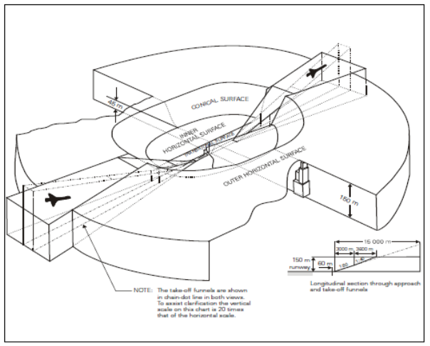
Figure GM-H-1. Disposition of Outer Horizontal Surface
[Issue: ADR-DSN/3]
CS ADR-DSN.H.415 Conical surface
ED Decision 2014/013/R
(a) Applicability: The purpose of the conical surface is to facilitate safe visual manoeuvring in the vicinity of the aerodrome.
(b) Description: A surface sloping upwards and outwards from the periphery of the inner horizontal surface.
(c) Characteristics: The limits of the conical surface should comprise:
(1) a lower edge coincident with the periphery of the inner horizontal surface; and
(2) an upper edge located at a specified height above the inner horizontal surface.
(d) The slope of the conical surface should be measured in a vertical plane perpendicular to the periphery of the inner horizontal surface.
CS ADR-DSN.H.420 Inner horizontal surface
ED Decision 2016/027/R
(a) Applicability: The purpose of the inner horizontal surface is to protect airspace for visual manoeuvring prior to landing.
(b) Description: A surface located in a horizontal plane above an aerodrome and its environs.
(c) Characteristics: The outer limits of the inner horizontal surface are defined by a circle centred on the geometric centre of the runway, by a convex contour composed of circular arcs centred on the intersections of the extended RWY centre line with the end of the RWY strip, joined tangentially by straight lines parallel to the runway centre line, as shown in Figure H-1, or on other points established for such purpose.
(d) The height of the inner horizontal surface should be measured above an established elevation datum. The elevation datum used for the height of the inner horizontal surface should be:
(1) the elevation of the highest point of the lowest threshold of the related runway; or
(2) the elevation of the highest point of the highest threshold of the related runway; or
(3) the elevation of the highest point of the runway; or
(4) the aerodrome elevation.
[Issue: ADR-DSN/3]
GM1 ADR-DSN.H.420 Inner horizontal surface
ED Decision 2016/027/R
(a) The shape of the inner horizontal surface need not necessarily be circular. Guidance on determining the extent of the inner horizontal surface is contained in the ICAO Doc 9137, Airport Services Manual, Part 6, Control of Obstacles.
(b) The limits of the inner horizontal surface for longer runways (1 800 m or more in length) are defined as circles of radius 4 000 m centred on the strip ends of the runway. These circles are joined by common tangents parallel to the runway centre line to form a racetrack pattern. The boundary of this pattern is the boundary of the inner horizontal surface.
(c) For runways less than 1 800 m in length, the inner horizontal surface may be defined as a circle centred on the midpoint of the runway.
(d) To protect two or more runways, a more complex pattern could become necessary. In this situation, all the circles are joined tangentially by straight lines: illustrated at the Figure GM-H-2.
(e) For relatively level runways the selection of elevation datum location is not critical, but when the thresholds differ by more than 6 m, the elevation datum should regard to the factors as the elevation of the most frequent used altimeter setting datum points, minimum circling altitudes in use or required and the nature of operations at the aerodrome. For more complex inner horizontal surfaces, with runways on different levels, as shown in Figure GM-H-2, a common elevation is not essential, but where surfaces overlap, the lower surface should be regarded as dominant.
(f) Further guidance is given in ICAO Doc 9137, Airport Services Manual, Part 6, Control of Obstacles.
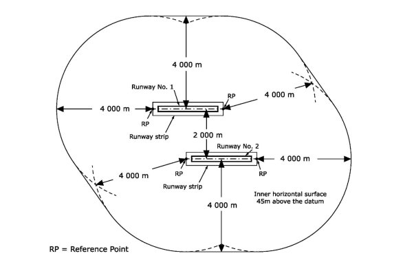
Figure GM-H-2. Composite inner horizontal surface for two parallel runways (where the runway code is 4)
[Issue: ADR-DSN/3]
CS ADR-DSN.H.425 Approach surface
ED Decision 2014/013/R
(a) Applicability: The purpose of the approach surface is to protect an aircraft during the final approach to the runway by defining the area that should be kept free from obstacles to protect an aeroplane in the final phase of the approach-to-land manoeuvre.
(b) Description: An inclined plane or combination of planes preceding the threshold.
(c) Characteristics. The limits of the approach surface should comprise:
(1) an inner edge of specified length, horizontal and perpendicular to the extended centre line of the runway, and located at a specified distance before the threshold;
(2) two sides originating at the ends of the inner edge and diverging uniformly at a specified rate from the extended centre line of the runway; and
(3) an outer edge parallel to the inner edge.
The above surfaces should be varied when lateral offset, offset or curved approaches are utilised, specifically, two sides originating at the ends of the inner edge and diverging uniformly at a specified rate from the extended centre line of the lateral offset, offset or curved ground track.
(d) The elevation of the inner edge should be equal to the elevation of the mid-point of the threshold.
(e) The slope(s) of the approach surface should be measured in the vertical plane containing the centre line of the runway and should continue containing the centre line of any lateral offset or curved ground track.
CS ADR-DSN.H.430 Transitional surface
ED Decision 2014/013/R
(a) Applicability: The purpose of the transitional surface is to define the limit of the area available for buildings, other structures or natural obstructions, such as trees.
(b) Description: A complex surface along the side of the strip and part of the side of the approach surface that slopes upwards and outwards to the inner horizontal surface.
(c) Characteristics: The limits of a transitional surface should comprise:
(1) a lower edge beginning at the intersection of the side of the approach surface with the inner horizontal surface and extending down the side of the approach surface to the inner edge of the approach surface and from there along the length of the strip parallel to the runway centre line; and
(2) an upper edge located in the plane of the inner horizontal surface.
(d) The elevation of a point on the lower edge should be:
(1) along the side of the approach surface — equal to the elevation of the approach surface at that point; and
(2) along the strip — equal to the elevation of the nearest point on the centre line of the runway or its extension.
(e) The slope of the transitional surface should be measured in a vertical plane at right angles to the centre line of the runway.
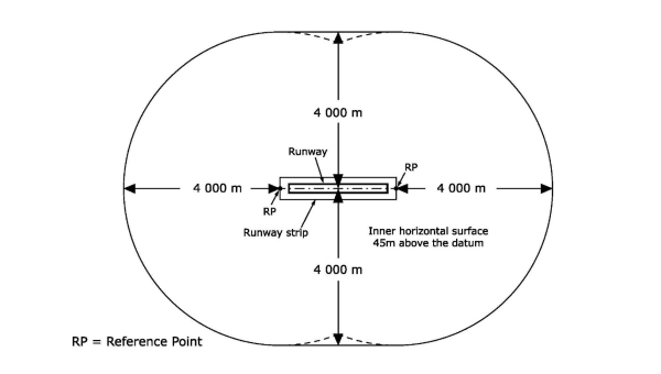
Figure H-1. Inner horizontal surface where the runway is code 4
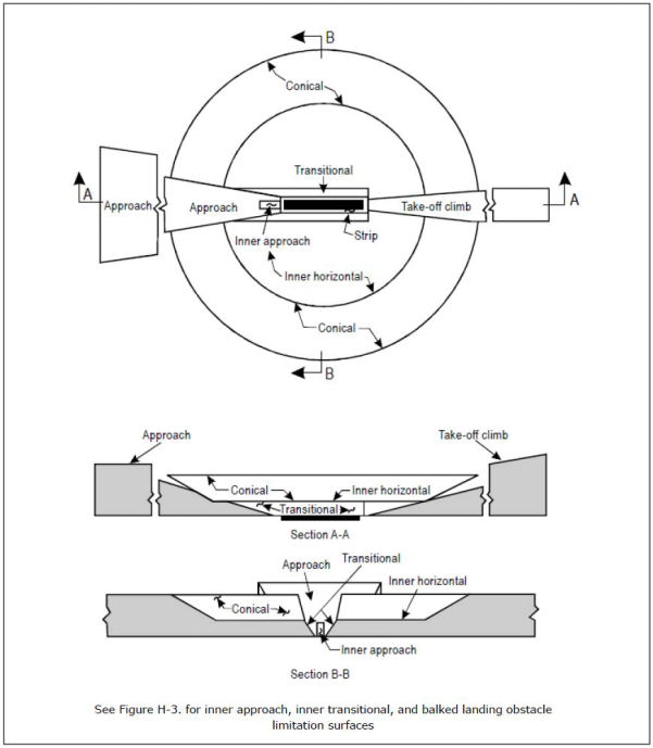
Figure H-2. Obstacle limitation surfaces
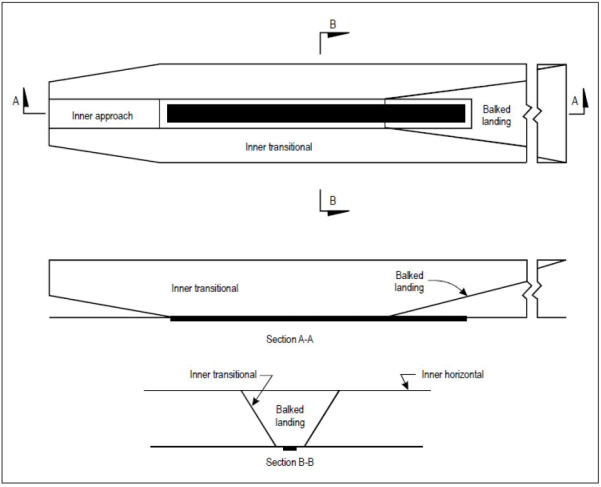
Figure H-3. Inner approach, inner transitional, and balked landing obstacle limitation surfaces
GM1 ADR-DSN.H.430 Transitional surface
ED Decision 2014/013/R
When the elevation of a point on the lower edge is along the strip and equal to the elevation of the nearest point on the centre line of the runway or its extension as a result the transitional surface along the strip should be curved if the runway profile is curved, or a plane if the runway profile is a straight line. The intersection of the transitional surface with the inner horizontal surface should also be a curved or a straight line depending on the runway profile.
CS ADR-DSN.H.435 Take-off climb surface
ED Decision 2014/013/R
(a) Applicability: The purpose of the take-off climb surface is to protect an aircraft on take-off and during climb-out.
(b) Description: An inclined plane or other specified surface beyond the end of a runway or clearway.
(c) Characteristics: The limits of the take-off climb surface should comprise:
(1) an inner edge horizontal and perpendicular to the centre line of the runway, and located either at a specified distance beyond the end of the runway, or at the end of the clearway when such is provided, and its length exceeds the specified distance;
(2) two sides originating at the ends of the inner edge, diverging uniformly at a specified rate from the take-off track to a specified final width and continuing thereafter at that width for the remainder of the length of the take-off climb surface; and
(3) an outer edge horizontal and perpendicular to the specified take-off track.
(d) The elevation of the inner edge should be equal to the highest point on the extended runway centre line between the end of the runway and the inner edge, except that when a clearway is provided, the elevation should be equal to the highest point on the ground on the centre line of the clearway.
(e) In the case of a straight take-off flight path, the slope of the take-off climb surface should be measured in the vertical plane containing the centre line of the runway.
(f) In the case of a take-off flight path involving a turn, the take-off climb surface should be a complex surface containing the horizontal normals to its centre line, and the slope of the centre line should be the same as that for a straight take-off flight path.
GM1 ADR-DSN.H.440 Slewed take-off climb surface
ED Decision 2016/027/R
The edge of a Take-off climb surface may be slewed in the direction of a turn away from the extended runway centre line up to a maximum of 15° splay. The portion of take-off climb surface encompassing the new departure track should be the same shape and dimensions as the original take-off climb surface measured relative to the new departure track. The opposite edge of the take-off climb surface should remain unchanged unless there is another turning departure towards that side as well, in which case, the edge may be slewed in that direction too.
[Issue: ADR-DSN/3]
CS ADR-DSN.H.445 Obstacle-free zone (OFZ)
ED Decision 2016/027/R
(a) An OFZ is intended to protect aeroplanes from fixed and mobile obstacles during Category II and III operations when approaches are continued below decision height, and during any subsequent missed approach or balked landing with all engines operating normally. It is not intended to supplant the requirement of other surfaces or areas where these are more demanding.
(b) The OFZ is made up of the following obstacle limitation surfaces:
(1) inner approach surface;
(2) inner transitional surfaces; and
(3) balked landing surface.
[Issue: ADR-DSN/3]
GM1 ADR-DSN.H.445 Obstacle-free zone (OFZ)
ED Decision 2016/027/R
intentionally left blank
[Issue: ADR-DSN/3]
CS ADR-DSN.H.450 Inner approach surface
ED Decision 2014/013/R
(a) Applicability: The purpose of the inner approach surface is to protect final precision approaches.
(b) Description: A rectangular portion of the approach surface immediately preceding the threshold.
(c) Characteristics: The limits of the inner approach surface should comprise:
(1) an inner edge coincident with the location of the inner edge of the approach surface but of its own specified length;
(2) two sides originating at the ends of the inner edge and extending parallel to the vertical plane containing the centre line of the runway; and
(3) an outer edge parallel to the inner edge.
CS ADR-DSN.H.455 Inner transitional surface
ED Decision 2014/013/R
(a) Applicability: The purpose of the inner transitional surface is to protect aeroplanes during precision approaches and balked landing.
(b) Description: A surface similar to the transitional surface but closer to the runway.
(c) Characteristics: The limits of an inner transitional surface should comprise:
(1) a lower edge beginning at the end of the inner approach surface and extending down the side of the inner approach surface to the inner edge of that surface, from there along the strip parallel to the runway centre line to the inner edge of the balked landing surface, and from there up the side of the balked landing surface to the point where the side intersects the inner horizontal surface; and
(2) an upper edge located in the plane of the inner horizontal surface.
(d) The elevation of a point on the lower edge should be:
(1) along the side of the inner approach surface and balked landing surface — equal to the elevation of the particular surface at that point; and
(2) along the strip — equal to the elevation of the nearest point on the centre line of the runway or its extension.
(e) The slope of the inner transitional surface should be measured in a vertical plane at right angles to the centre line of the runway.
GM1 ADR-DSN.H.455 Inner transitional surface
ED Decision 2014/013/R
(a) It is intended that the inner transitional surface be the controlling obstacle limitation surface for navigation aids, aircraft, and other vehicles that should be near the runway, and which is not to be penetrated except for frangible objects. The transitional surface is intended to remain as the controlling obstacle limitation surface for buildings, etc.
(b) The inner transitional surface along the strip should be curved if the runway profile is curved or a plane if the runway profile is a straight line. The intersection of the inner transitional surface with the inner horizontal surface should also be a curved or straight line depending on the runway profile.
CS ADR-DSN.H.460 Balked landing surface
ED Decision 2014/013/R
(a) Applicability: The purpose of the balked landing surface is to protect balked landing.
(b) Description: An inclined plane located at a specified distance after the threshold, extending between the inner transitional surfaces.
(c) Characteristics: The limits of the balked landing surface should comprise:
(1) an inner edge horizontal and perpendicular to the centre line of the runway and located at a specified distance after the threshold;
(2) two sides originating at the ends of the inner edge and diverging uniformly at a specified rate from the vertical plane containing the centre line of the runway; and
(3) an outer edge parallel to the inner edge and located in the plane of the inner horizontal surface.
(d) The elevation of the inner edge should be equal to the elevation of the runway centre line at the location of the inner edge.
(e) The slope of the balked landing surface should be measured in the vertical plane containing the centre line of the runway.