ADR.OPS.C.005 Maintenance — General
Delegated Regulation (EU) 2020/2148
(a) The aerodrome operator shall establish and implement a maintenance programme, which includes preventive maintenance where appropriate, to maintain aerodrome facilities, systems and equipment necessary for the operation of the aerodrome in a condition which does not impair the safety, regularity or efficiency of air navigation. The design and implementation of the maintenance programme shall observe human factors principles.
(b) The aerodrome operator shall ensure that appropriate and adequate means are provided for the effective implementation of the maintenance programme.
ED Decision 2021/003/R
MAINTENANCE PROGRAMME
(a) The aerodrome operator should ensure that the maintenance programme:
(1) specifies the aerodrome facilities, systems, installations and equipment subject to maintenance;
(2) contains the necessary information for its timely and correct implementation including but not limited to:
(i) the type of inspections/checks to be carried out (e.g. visual inspection, cleaning of equipment, equipment stability/alignment, calibration, etc.) for each facility, system, installation and equipment, taking also into account factors such as their location and meteorological phenomena;
(ii) the frequency of inspections/checks for each facility, system, installation and equipment;
(iii) the tools and equipment required for each type of inspection/check; and
(iv) the periodic replacement of parts that may be required in accordance with the maintenance instructions of the manufacturer of the respective facility, system, installation and equipment, as appropriate.
(b) The aerodrome operator should ensure that arrangements are in place for timely corrective maintenance actions. Such arrangements should cover the cases of maintenance needs that are:
(1) identified either during preventive maintenance activities; or
(2) raised at any other time (e.g. due to equipment malfunction or failure).
ED Decision 2021/003/R
MAINTENANCE PROGRAMME
The maintenance programme also includes maintenance of communication and alerting systems, fences and access control devices, perimeter roads and lighting, passenger boarding bridges, etc.
ADR.OPS.C.007 Maintenance of vehicles
Delegated Regulation (EU) 2020/2148
(a) The aerodrome operator shall:
(1) establish and implement a maintenance programme, which includes preventive maintenance and observes human factors principles, for rescue and firefighting vehicles, to ensure effectiveness of the vehicles and their equipment and compliance with the specified response time throughout the life of the vehicle;
(2) ensure the implementation of a maintenance programme for its other vehicles that operate on the movement area or other operational areas.
(b) The aerodrome operator shall:
(1) establish procedures to support the implementation of the maintenance programme referred to in point (a);
(2) ensure that appropriate and adequate means and facilities are provided for its effective implementation;
(3) keep maintenance records for each vehicle.
(c) The aerodrome operator shall ensure that organisations that operate or provide services at the aerodrome:
(1) maintain their vehicles that operate on the movement area or other operational areas, in accordance with an established maintenance programme, including preventive maintenance;
(2) keep relevant maintenance records.
(d) The aerodrome operator shall ensure that unserviceable vehicles are not used for operations.
AMC1 ADR.OPS.C.007(a) Maintenance of vehicles
ED Decision 2021/003/R
MAINTENANCE OF VEHICLES — GENERAL
The maintenance of the vehicles may be performed by the aerodrome operator or by a contracted organisation. The maintenance programme should be individual for each vehicle, depending on its function and characteristics. The maintenance programme should take into account the following:
(a) regulatory requirements (e.g. certification of pressure vessels, hoses, roadworthiness certificates);
(b) the manufacturer’s maintenance recommendations;
(c) local environmental conditions (e.g. heat versus cold winters);
(d) the need to ensure the serviceability of the equipment installed on the vehicle (e.g. radio, transponders or equivalent systems); and
(e) regular performance test results, if appropriate.
AMC1 ADR.OPS.C.007(a)(1) Maintenance of vehicles
ED Decision 2021/003/R
PREVENTIVE MAINTENANCE
(a) As part of the preventive maintenance programme, the aerodrome operator should determine the items that need to be checked daily, prior to the operation of the vehicle. As a minimum, the following items should be checked on a daily basis, prior to the operation of a vehicle:
(1) malfunction/warning indications;
(2) steering wheel;
(3) lighting system;
(4) braking system;
(5) communication systems, including transponder (or equivalent) if applicable;
(6) tyre condition;
(7) external mirrors;
(8) windscreen wipers (as appropriate);
(9) items that need to be secured on the vehicle;
(10) leaks; and
(11) new external damages to the vehicle.
(b) A feedback mechanism should be established to ensure that any defects identified are communicated to the unit responsible for the maintenance of the vehicle.
GM1 ADR.OPS.C.007(a)(2) Maintenance of vehicles
ED Decision 2021/003/R
As part of the maintenance programme for all its other vehicles, the aerodrome operator may, in the interest of safety, determine the items that need to be checked daily prior to their use, and communicate any defects identified during such checks to the unit responsible for the maintenance of the vehicle.
AMC1 ADR.OPS.C.007(b)(1) Maintenance of vehicles
ED Decision 2021/003/R
MAINTENANCE PROCEDURES — GENERAL
Maintenance procedures should be established to ensure a standardised manner in which vehicles are maintained and should cover as a minimum:
(a) activities to be undertaken to ensure that disruption to aerodrome services (e.g. RFFS) is minimised;
(b) the frequency of maintenance services;
(c) activities to be undertaken at each type of maintenance service (e.g. visual check, inspections, measurements, etc.);
(d) arrangements for technical support from the manufacturer;
(e) spare parts that should be kept on site;
(f) procedures to ensure the safety of maintenance personnel;
(g) environmental procedures, including appropriate disposal procedures for old parts, and other material; and
(h) documentation and reporting of any defects that have been identified by operational and/or maintenance personnel.
AMC1 ADR.OPS.C.007(b)(2) Maintenance of vehicles
ED Decision 2021/003/R
MAINTENANCE FACILITIES — GENERAL
If maintenance services and/or facilities are provided by a contracted organisation (located at the aerodrome or elsewhere), the aerodrome operator should have in place arrangements, to allow the timely maintenance of the vehicles in order to avoid disruptions to aerodrome operations.
Irrespective of the solution chosen, the aerodrome operator should ensure:
(a) the adequacy of the facilities for the maintenance activities and the storage of spare parts and other material;
(b) the provision of tools and equipment necessary for the maintenance activities, especially for RFFS vehicles and related equipment;
(c) the availability of maintenance documentation; and
(d) the provision of appropriate and adequate training to the personnel involved in maintenance activities.
AMC1 ADR.OPS.C.007(b)(3) Maintenance of vehicles
ED Decision 2021/003/R
MAINTENANCE RECORDS
The maintenance records, as a minimum, should include the following:
(a) maintenance type (preventive/corrective);
(b) items checked/repaired;
(c) maintenance date (entry/exit date to/from the workshop); and
(d) name of the person that conducted the inspection/repair.
AMC1 ADR.OPS.C.007(c) Maintenance of vehicles
ED Decision 2021/003/R
MAINTENANCE OF VEHICLES — OTHER ORGANISATIONS
The aerodrome operator should establish and implement an audit programme and/or control mechanism that allows ensuring compliance of the organisations operating or providing services at the aerodrome.
A feedback mechanism should be established with the aerodrome unit responsible for authorising the operation of vehicles as per ADR.OPS.B.026, to enable it to take appropriate action.
AMC2 ADR.OPS.C.007(c) Maintenance of vehicles
ED Decision 2021/003/R
MAINTENANCE OF VEHICLES — OTHER ORGANISATIONS
(a) The maintenance programme should be individual for each vehicle, depending on its function and characteristics. The maintenance programme should take into account the following:
(1) applicable regulatory requirements;
(2) the manufacturer’s maintenance recommendations;
(3) local environmental conditions (e.g. heat versus cold winters);
(4) the need to ensure the serviceability of the equipment installed on the vehicle (e.g. radio, transponders); and
(5) regular performance test results, if appropriate.
(b) With regard to maintenance procedures, they should include at least specify:
(1) the frequency of the maintenance services;
(2) activities to be undertaken at each type of maintenance service (e.g. visual check, inspections, etc.); and
(3) environmental procedures, including appropriate disposal procedures for old parts and other material.
(c) With regard to preventive maintenance, AMC1 ADR.OPS.C.007(a)(1) applies.
(d) With regard to record-keeping, AMC1 ADR.OPS.C.007(b)(3) applies.
GM1 ADR.OPS.C.007(d) Maintenance of vehicles
ED Decision 2021/003/R
UNINTENDED USE OF UNSERVICEABLE VEHICLES
Apart from the obligation to ensure that an unserviceable vehicle is removed from operations, measures also need to be taken to avoid the unintended use of an unserviceable vehicle. The latter may include the placing of a warning placard inside the vehicle to inform about the unserviceability of the vehicle, and the establishment of a method for the provision of such information to the relevant personnel, especially those of the next shift.
ADR.OPS.C.010 Maintenance of pavements, other ground surfaces and drainage
Delegated Regulation (EU) 2020/2148
(a) The aerodrome operator shall inspect the surfaces of all movement areas including pavements (runways, taxiways and aprons), adjacent areas and drainage to regularly assess their condition as part of an aerodrome preventive and corrective maintenance programme.
(b) The aerodrome operator shall:
(1) maintain the surfaces of all movement areas with the objective of avoiding and eliminating any FOD that might cause damage to aircraft or impair the operation of aircraft systems;
(2) maintain the surface of runways, taxiways and aprons in order to prevent the formation of harmful irregularities;
(3) maintain the runway in a condition so as to provide surface friction characteristics at or above the minimum standards;
(4) periodically inspect and document the runway surface friction characteristics for maintenance purposes. The frequency of those inspections shall be sufficient to determine the trend of the surface friction characteristics of the runway;
(5) take corrective maintenance action to prevent the runway surface friction characteristics for either the entire runway or a portion thereof, when uncontaminated, from falling below the minimum standards.
AMC1 ADR.OPS.C.010 Maintenance of pavements, other ground surfaces and drainage
ED Decision 2021/003/R
GENERAL
(a) Mud, dust, sand, oil, rubber deposits, and other pollutants should be removed, as rapidly and completely as possible, to minimise accumulation.
(b) Taxiways and aprons should be kept clear of pollutants to the extent necessary to enable aircraft to be taxied to and from an operational runway.
(c) Drainage systems and storm water collection systems should be periodically checked and, if necessary cleaned or maintained, to ensure efficient water run-off.
(d) The surface of a paved runway should be evaluated when constructed or resurfaced to determine that the surface friction characteristics achieve the design objectives.
GM1 ADR.OPS.C.010(b)(1) Pavements, other ground surfaces, and drainage
ED Decision 2021/003/R
OVERLOAD OPERATIONS
(a) Overloading of pavements can result either from loads too large, or from a substantially increased application rate, or both. Loads larger than the defined (design or evaluation) load shorten the design life, whilst smaller loads extend it. With the exception of massive overloading, pavements in their structural behaviour are not subject to a particular limiting load above which they suddenly or catastrophically fail. Behaviour is such that a pavement can sustain a definable load for an expected number of repetitions during its design life. As a result, occasional minor overloading is acceptable, when expedient, with only limited loss in pavement life expectancy, and relatively small acceleration of pavement deterioration. For those operations in which magnitude of overload and/or the frequency of use do not justify a detailed analysis, the following criteria are suggested:
(1) for flexible pavements, occasional movements by aircraft with ACN not exceeding 10 % above the reported PCN should not adversely affect the pavement;
(2) for rigid or composite pavements, in which a rigid pavement layer provides a primary element of the structure, occasional movements by aircraft with ACN not exceeding 5 % above the reported PCN should not adversely affect the pavement;
(3) if the pavement structure is unknown, the 5 % limitation should apply; and
(4) the annual number of overload movements should not exceed approximately 5 % of the total annual aircraft movements.
(b) Such overload movements should not normally be permitted on pavements exhibiting signs of distress or failure. Furthermore, overloading should be avoided during any periods of thaw following frost penetration, or when the strength of the pavement or its subgrade could be weakened by water. Where overload operations are conducted, the aerodrome operator should review the relevant pavement condition regularly, and should also review the criteria for overload operations periodically since excessive repetition of overloads can cause severe shortening of pavement life, or require major rehabilitation of pavement.
GM1 ADR.OPS.C.010(b)(2) Pavements, other ground surfaces and drainage
ED Decision 2021/003/R
RUNWAY SURFACE EVENNESS
(a) The operation of aircraft and differential settlement of surface foundations will eventually lead to increases in surface irregularities. Small deviations in the above tolerances will not seriously hamper aircraft operations. In general, isolated irregularities of the order of 2.5 cm to 3 cm over a 45 m-distance are acceptable, as shown in Figure 1. Although maximum acceptable deviations vary with the type and speed of an aircraft, the limits of acceptable surface irregularities can be estimated to a reasonable extent. The following table describes acceptable, tolerable and excessive limits:
|
Surface Irregularity |
Length of irregularity (m) |
||||||||
|
3 |
6 |
9 |
12 |
15 |
20 |
30 |
45 |
60 |
|
|
Acceptable surface irregularity height (cm) |
2.9 |
3.8 |
4.5 |
5 |
5.4 |
5.9 |
6.5 |
8.5 |
10 |
|
Tolerable surface irregularity height (cm) |
3.9 |
5.5 |
6.8 |
7.8 |
8.6 |
9.6 |
11 |
13.6 |
16 |
|
Excessive surface irregularity height (cm) |
5.8 |
7.6 |
9.1 |
10 |
10.8 |
11.9 |
13.9 |
17 |
20 |
Table 1
(1) If the surface irregularities exceed the heights defined by the acceptable limit curve but are less than the heights defined by the tolerable limit curve, at the specified minimum acceptable length, herein noted by the tolerable region, then maintenance action should be planned. The runway may remain in service. This region is the start of possible passenger and pilot discomfort.
(2) If the surface irregularities exceed the heights defined by the tolerable limit curve, but are less than the heights defined by the excessive limit curve, at the specified minimum acceptable length, herein noted by the excessive region, the maintenance corrective action is mandatory to restore the condition to the acceptable region. The runway may remain in service but should be repaired within a reasonable period. This region could lead to the risk of possible aircraft structural damage due to a single event or fatigue failure over time.
(3) If the surface irregularities exceed the heights defined by the excessive limit curve, at the specified minimum acceptable length, herein noted by the unacceptable region, then the area of the runway where the roughness has been identified warrants closure. Repairs are required to restore the condition within the acceptable limit region and the aircraft operators may be advised accordingly. This region runs the extreme risk of a structural failure and must be addressed immediately.
(b) The term ‘surface irregularity’ is defined herein to mean isolated surface elevation deviations that do not lie along a uniform slope through any given section of a runway. For the purposes of this concern, a ‘section of a runway’ is defined herein to mean a segment of a runway throughout which a continuing general uphill, downhill, or flat slope is prevalent. The length of this section is generally between 30 and 60 m, and can be greater, depending on the longitudinal profile and the condition of the pavement.
(c) The maximum tolerable step-type bump, such as that which could exist between adjacent slabs, is simply the bump height corresponding to zero bump length at the upper end of the tolerable region of the roughness criteria of Figure 1.
(d) Deformation of the runway with time may also increase the possibility of the formation of water pools. Pools as shallow as approximately 3 mm in depth, particularly if they are located where they are likely to be encountered at high speed by landing aeroplanes, can induce aquaplaning which can then be sustained on a wet runway by a much shallower depth of water. Improved guidance regarding the significant length and depth of pools relative to aquaplaning is the subject of further research. It is, of course, especially necessary to prevent pools from forming whenever there is a possibility that they might become frozen.
(e) Macrotexture and microtexture are taken into consideration in order to provide the required surface friction characteristics. This normally requires some form of special surface treatment.
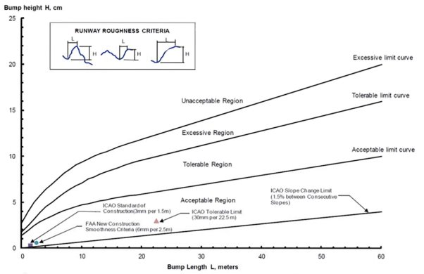
Figure 1
AMC1 ADR.OPS.C.010(b)(3) Maintenance of pavements, other ground surfaces and drainage
ED Decision 2021/003/R
MAINTENANCE PLANNING AND MINIMUM STANDARDS
(a) When friction measuring devices are used in order to evaluate the condition of the runway surface for maintenance purposes, the maintenance planning and minimum friction levels should be according to the following table:
|
|
65 km/h |
95 km/h |
||
|
|
Minimum |
Maintenance planning |
Minimum |
Maintenance planning |
|
Airport Surface Friction Tester |
0.50 |
0.60 |
0.34 |
0.47 |
|
Dynatest Consulting Inc. Dynatest Runway Friction Tester |
0.50 |
0.60 |
0.41 |
0.54 |
|
Findlay, Irvine, Ltd Griptester Friction Meter |
0.43 |
0.53 |
0.24 |
0.36 |
|
Halliday Technologies RT3 |
0.45 |
0.55 |
0.42 |
0.52 |
|
Moventor Oy Inc. BV-11 Skiddometer |
0.50 |
0.60 |
0.34 |
0.47 |
|
Mu Meter |
0.42 |
0.52 |
0.26 |
0.38 |
|
NAC Dynamic Friction Tester |
0.42 |
0.52 |
0.28 |
0.38 |
|
Norsemeter RUNAR (operated at fixed 16 % slip) |
0.45 |
0.52 |
0.32 |
0.42 |
|
Automatic Friction Measuring Device (Instrument de Mesure Automatique de Glissance) – IMAG |
0.30 |
0.40 |
0.20 |
0.30 |
Table 1
(b) Other friction measuring devices can be used, provided they have been correlated with, at least, one test equipment mentioned in the table above.
(c) Measurements at or below the maintenance planning level trigger a complete survey of the texture, contaminant and drainage state of the affected runway third.
(d) A complete survey should ensure that the runway surface is able to create enough grip by the aeroplane tyre to ensure adequate aeroplane stopping and crosswind capability for the desired operation on a wet runway. This is achieved by ensuring that:
(1) exposed texture can indent the tyre rubber; and
(2) water drains from the runway pavement.
(e) In order to achieve the objectives of point (d), an inspection of the surface friction characteristics should, as a minimum, ensure:
(1) the presence of exposed microtexture by touching the aggregates, if the polished or rubber coated extends to 100 m in the zone used by aeroplanes;
(2) the presence of macrotexture;
(3) that grooves, if present, are open and within set limits according to their design;
(4) that porous friction course, if present, drains according to its design; and
(5) that slopes are above minimum design specifications.
GM1 ADR.OPS.C.010(b)(3) Pavements, other ground surfaces and drainage
ED Decision 2021/003/R
MONITORING OF PHYSICAL PARAMETERS
The following table describes how the physical parameters of the runway surface are monitored.
|
Physical parameter |
How to monitor |
|
Microtexture |
Presence of microtexture is ensured by touching the pavement surface. If it feels smooth, there is a lack of microtexture, most commonly due to rubber deposits which normally should be visually detectable or by polishing. In either case, the amount of free exposed microtexture should be assessed. |
|
Macrotexture |
Can be measured using volumetric or profile measurement method and expressed by ESDU classification. ESDU 15002 groups runways into five classifications labelled A through E with A being the smoothest and E the most heavily textured. The classification can be used to compare the runway texture relevant to the recommended texture depth which is 1.0 mm. |
|
Drainage |
Slopes are within the certification specifications. If the slope falls below the minimum values, then the runway becomes more susceptible to standing water during heavy rainfalls. |
|
Ponding |
Visually, during and after rain storm events as the runway dries up. |
|
Rutting |
Visually, during and after rain storm events. The degree of rutting can be measured using a straight edge. |
|
Sand and vegetation |
Visually during and after rain storm events. Normally, ordinary maintenance activities should prevent sand to accumulate and vegetation to form alongside the runway to such a degree that it becomes a hazard. |
AMC1 ADR.OPS.C.010(b)(4) Maintenance of pavements, other ground surfaces and drainage
ED Decision 2021/003/R
PERIODIC ASSESSMENTS OF RUNWAY SURFACE FRICTION CHARACTERISTICS
The aerodrome operator when establishing a plan of periodic assessments of runway surface friction characteristics, should take into consideration the number of jet aircraft movements per runway end, the weight of the aircraft, the type and age of the surface of the runway as well as climatic conditions.
AMC2 ADR.OPS.C.010(b)(4) Maintenance of pavements, other ground surfaces and drainage
ED Decision 2021/003/R
TREND MONITORING OF RUNWAY SURFACE FRICTION CHARACTERISTICS
The aerodrome operator should monitor the trend of degradation of runway surface friction characteristics that is caused by:
(a) rubber deposits;
(b) surface polishing; and
(c) poor drainage.
AMC3 ADR.OPS.C.010(b)(4) Maintenance of pavements, other ground surfaces and drainage
ED Decision 2021/003/R
FUNCTIONAL FRICTION EVALUATIONS WITH CONTINUOUS FRICTION MEASURING DEVICES
The aerodrome operator when conducting functional friction evaluations with continuous friction measuring device, should:
(a) for friction evaluations on runways at 65 km/h, begin recording the data 150 m from the threshold end to allow for adequate acceleration distance and terminate approximately 150 m from the opposite end of the runway to allow for adequate distance to safely decelerate the vehicle;
(b) for friction evaluations on runways at 95 km/h, begin recording the data 300 m from the threshold end to allow for adequate acceleration distance and terminate approximately 300 m from the opposite end of the runway to allow for adequate distance to safely decelerate the vehicle; and
(c) conduct the surveys at a distance from the runway centre line that is representative of the wheel span of the aeroplanes operating on the runway.
The aerodrome layout or other circumstances may dictate other distances in order to ensure the personal safety of the operator of the friction measuring device.
AMC4 ADR.OPS.C.010(b)(4) Maintenance of pavements, other ground surfaces and drainage
ED Decision 2021/003/R
RUNWAY SURFACE FRICTION CHARACTERISTICS EVALUATION WITHOUT FRICTION MEASURING DEVICES
(a) The evaluation should be conducted for the full width and length of the pavement and should focus on:
(1) slopes;
(2) texture; and
(3) drainage.
(b) The area symmetrical from the centre line representative of the wheel span of the aeroplanes operating on the runway should be inspected with special focus on:
(1) rubber deposits;
(2) polishing of aggregates; and
(3) amount of exposed texture.
GM1 ADR.OPS.C.010(b)(4) Maintenance of pavements, other ground surfaces and drainage
ED Decision 2021/003/R
TREND MONITORING PROGRAMME
(a) The objective of the trend monitoring programme is to ensure that the surface friction characteristics for the entire runway remain at or above the minimum standards, to avoid the runway becoming slippery wet.
(b) Degradation is typically caused by rubber deposits, surface polishing or poor drainage. These can be mitigated as follows:
(1) Accumulation trend of rubber can be managed through a rubber removal programme.
(2) Polishing trend of the surface can be managed by monitoring loss of sharpness and retexturing/resurfacing programme.
(3) Drainage trend can be managed by monitoring changes in geometry and blocking of drainage channels and reshaping programme.
(c) In the construction of new runways or the resurfacing of existing runways, the construction of surfaces with adequate slopes and aggregate of angular fragments from crushed gravel or stone so as to provide a sharp texture will help to ensure surface friction characteristics providing good braking action in wet conditions. The surface friction characteristics of a new constructed or resurfaced runway surface establish the normal starting point for trend monitoring; however, trend monitoring can also start at any given time through the lifespan of a pavement.
(d) The determination that a runway or portion thereof is slippery wet stems from various methods used by themselves or in combination. Additionally, substandard runways or portion thereof can be identified through repeated reports by aeroplane operators based upon flight crew experience or through analysis of aeroplane stopping performance. When such reports are received, it is an indication that the surface friction characteristics are likely to be severely degraded and immediate remedial action is necessary.
GM2 ADR.OPS.C.010(b)(4) Maintenance of pavements, other ground surfaces and drainage
ED Decision 2021/003/R
FRICTION EVALUATIONS WITH CONTINUOUS FRICTION MEASURING DEVICES
(a) The lateral location on the runway for performing friction measurements is based on the type and/or mix of aircraft operating on the runway:
(1) For runways serving only narrow-body aircraft, friction measurements are conducted 3 m to 5 m from the runway centre line.
(2) For runways serving narrow-body and wide-body aircraft, friction measurements are conducted 3 m and 6 m from the runway centre line to determine the worst-case condition. If the worst-case condition is found to be consistently to one track, future measurements may be limited to this track. Care needs to be exercised, however, to account for any future and/or seasonal changes in aircraft mix.
(b) The measurements are performed using a self-wetting continuous friction measuring device on a dry runway surface.
(c) Interpretation of comparative self-wetting friction measurements
(1) The texture of the tyre pavement contact patch area in direct contact with aircraft tyre penetrates the rubber of the aircraft tyre and creates horizontal forces in the aircraft tyre and creates grip. Grip is a micro-movement of the rubber over the texture indenting the rubber. This micro-movement is called slippage. On a free-rolling aircraft tyre, there is no relative movement between the aircraft tyre and the pavement regardless of the rolling speed. The amount of exposed texture, and the quality thereof, both micro and macrotexture, defines the ability of the pavement surface to create wet grip performance of the aircraft tyre.
(2) If the aircraft wheel is braked and the horizontal forces applied on the aircraft tyre are higher than those produced by the grip, the aircraft tyre starts to skid.
(3) The friction coefficient that can be calculated is a dynamic friction coefficient. The dynamic friction coefficient is lower than the static friction coefficient (maximum tyre grip that can be achieved). Related to stopping performance of the aircraft, the operation has become friction-limited when a tyre starts skidding.
(4) The basic assumption for the using a self-wetting continuous friction measuring device with a forced skid is to mirror a braked skidding aircraft tyre on a wet pavement surface. This is an oversimplification since the aircraft tyres are controlled by an anti-skid system and the friction measuring devices operate at a fixed slip.
(5) It is noted that friction measuring device values are not used to determine and report surface conditions. Joint industry and multi-national government tests have not established a reliable correlation between runway friction values and the relationship to aeroplane braking performance. However, the measured values can be used in a comparative way to support other survey information collected.
(6) The measured friction coefficient is a dynamic friction coefficient where the surfaces are forced to be in relative motion regardless of the measuring speed. The degree of relative motion is friction measuring device-specific.
(7) A complete survey is, as a minimum, performed at speeds of 65 km/h and 95 km/h.
(8) The measured value is an indication of the overall texture, contaminant and drainage capability of the pavement surface in the tyre pavement contact patch area of a skidding tyre. No single capability can be extracted but certain qualities can be deduced from comparative measurements using the same friction measurement device on the same surface.
(9) The measured values are to be compared with measured values from previous surveys in order to monitor the trend of the texture, contaminant and drainage characteristics of the runway pavement.
(i) Texture
(A) At low speed, the microtexture of the aggregates in the tyre pavement contact patch area penetrates the residual water film between the pavement and the rubber. These are qualities associated with 65 km/h. Lower comparative values at low speed indicate reduced exposed microtexture and are indicative of microtexture cover-up (rubber) and polishing of aggregates.
(B) At higher speed,the microtexture may not penetrate the residual water film. As speed increases, the residual water film may become thicker and reduce the amount of microtexture that penetrates the water film. If no microtexture penetrates the water film, there is no effect of the microtexture on the performance of the aircraft tyre. The tyre then goes into an aquaplaning mode with no stopping and directional control capability. These are qualities associated with 95 km/h, and lower comparative values are indicative of the combined rubber build-up and reduced drainage capability.
(C) Macrotexture creates escape channels for bulk water and reduces the susceptibility of the pavement surface to build up water films under the aircraft tyre. Lower comparative values at high speed indicate reduced macrotexture.
(ii) Contaminant
(A) The most common contaminant to consider is the build-up of rubber. Build– up of rubber reduces the amount of exposed microtexture and the fill-up of the macrotexture, and thereby reduces the drainage capability of the pavement in the tyre pavement contact patch area. Affected areas can readily be identified by the eye.
(B) If the aerodrome operator suspects that the runway has a microtexture problem, this can be identified by the touch; pavement surface does feel ‘sandpapery’. This applies to both rubber build-up, where the aggregates get covered, and the polishing of aggregates.
(C) For interpretation of comparative measurements on rubber built-up areas, see (i) Texture above.
(10) Drainage
(i) The aircraft tyres’ contribution to drainage is the drainage through the longitudinal grooves. The pavements’ contribution is the drainage through their macrotexture. This drainage can be in all directions, and in the case of porous friction course drainage downwards, through the porous friction course layer itself. If the pavement is transverse grooved, the drainage in the transverse direction of travel is enhanced. Lower comparative values at high speed indicate reduced drainage capability under the aircraft tyre and reduced macrotexture.
(ii) It should be noted that the effects of drainage defects, such as ponding and rutting, will not be detected by comparative measurements by self-wetting continuous friction measuring devices. As the self-wetting continuous friction measurements are performed on a dry runway, there will be no ponding, nor any water stream in any rutting if the runway has such defects.
ADR.OPS.C.015 Maintenance of visual aids and electrical systems
Delegated Regulation (EU) 2020/2148
(a) The aerodrome operator shall establish and implement a preventive and corrective maintenance programme to ensure the serviceability of the electrical systems and the availability of power supply to all necessary facilities of the aerodrome, in a manner that ensures the safety, regularity and efficiency of air navigation.
(b) The aerodrome operator shall establish and implement a preventive and corrective maintenance programme to ensure the serviceability of the individual lights and the aerodrome’s lighting systems reliability, in a manner that ensures continuity of guidance to, and control of aircraft and vehicles, as follows:
(1) For a precision approach runway Category II or III, the system of preventive maintenance shall have as its objective that, during any period of Category II or III operations, all approach and runway lights are serviceable and that, in any event, at least:
(i) 95 % of the lights are serviceable in each of the following elements:
(A) precision approach Category II and III lighting system, the inner 450 m;
(B) runway centre line lights;
(C) runway threshold lights;
(D) runway edge lights.
(ii) 90 % of the lights are serviceable in the touchdown zone lights;
(iii) 85 % of the lights are serviceable in the approach lighting system beyond 450 m;
(iv) 75 % of the lights are serviceable in the runway-end lights.
(2) The lights that may be unserviceable in accordance with point (1) shall not alter the basic pattern of the lighting system.
(3) An unserviceable light shall not be permitted adjacent to another unserviceable light, except in a barrette or a crossbar where two adjacent unserviceable lights may be permitted.
(4) For a stop bar that is provided at a runway-holding position and is used in conjunction with a runway intended for operations in runway visual range conditions less than a value of 550 m, the system of preventive maintenance shall have the following objectives:
(i) no more than two lights shall remain unserviceable;
(ii) two adjacent lights shall not remain unserviceable unless the light spacing is significantly less than that required.
(5) For a taxiway intended for use in runway visual range conditions less than a value of 550 m, the system of preventive maintenance shall have as its objective that no two adjacent taxiway centre line lights be unserviceable.
(6) For a precision approach runway Category I, the system of preventive maintenance employed shall have as its objective that, during any period of Category I operations, all approach and runway lights are serviceable and that, in any event:
(i) at least 85 % of the lights are serviceable in each of the following:
(A) precision approach Category I lighting system;
(B) runway threshold lights;
(C) runway edge lights;
(D) runway-end lights;
(ii) an unserviceable light shall not be permitted adjacent to another unserviceable light unless the light spacing is significantly less than that required.
(7) For a runway meant for take-off in runway visual range conditions less than a value of 550 m, the system of preventive maintenance shall have as its objective that, during any period of operations, all runway lights are serviceable, and that, in any event:
(i) at least:
(A) 95 % of the lights are serviceable in the runway centre line lights (where provided) and in the runway edge lights;
(B) 75 % of the lights are serviceable in the runway-end lights;
(ii) an unserviceable light shall not be permitted adjacent to another unserviceable light.
(8) For a runway meant for take-off in runway visual range conditions of a value of 550 m or greater, the system of preventive maintenance shall have as its objective that, during any period of operations, all runway lights are serviceable, and that, in any event:
(i) at least 85 % of the lights are serviceable in the runway edge lights and runway-end lights;
(ii) an unserviceable light shall not be permitted adjacent to another unserviceable light.
(9) For a runway equipped with visual approach slope indicator systems, the system of preventive maintenance shall have as its objective that, during any period of operations, all units are serviceable. A unit shall be considered unserviceable if the number of unserviceable lights is such that the unit does not provide the intended guidance to the aircraft.
(c) For the purposes of point (b), a light shall be deemed to be unserviceable if:
(1) the main beam average intensity is less than 50 % of the value specified in the certification specifications issued by the Agency. For light units where the designed main beam average intensity is above the value specified in the certification specifications issued by the Agency, the 50 % value shall be related to that design value;
(2) the filter associated with the light is missing, damaged, or the light does not produce the correct colour light beam.
(d) The aerodrome operator shall establish and implement a preventive and corrective maintenance programme to ensure the serviceability and reliability of the system of markings and signs of the aerodrome, in a manner that ensures continuity of guidance to, and control of aircraft and vehicles.
(e) Construction or maintenance activities shall not take place in the proximity of aerodrome electrical systems when low-visibility procedures are in effect at the aerodrome.
(f) The aerodrome operator shall ensure that:
(1) the preventive maintenance programmes referred to in points (a), (b) and (d) include appropriate inspections and checks of the individual elements of each system, and of the system itself, which are conducted in accordance with established procedures, and at defined intervals, appropriate to the intended operation and system;
(2) appropriate corrective actions are taken to rectify any identified defects.
(g) The aerodrome operator shall maintain records of the relevant maintenance activities.
AMC1 ADR.OPS.C.015(a);(f) Maintenance of visual aids and electrical systems
ED Decision 2021/003/R
ELECTRICAL SYSTEMS
(a) Schedules of routine maintenance of the individual elements of the aerodrome’s electrical systems should be based on manufacturers' instructions, adjusted to the aerodrome operator's experience regarding the frequency of malfunctions.
(b) The maintenance programme should, as a minimum, include the following:
(1) power cables and distributors in field;
(2) transformers and regulators;
(3) transformer stations for electric power supply;
(4) relay and switch cabinets;
(5) control cables, monitoring units and control desk;
(6) secondary power supply; and
(7) fixed ground power supply for aircraft,
and should contain the frequency of the scheduled maintenance activities and the elements that should be checked during each inspection.
(c) Checklists to be used during the scheduled maintenance activities should be developed by the aerodrome operator.
(d) The relevant procedures should cover the maintenance activities for each area, including the way such activities should be implemented.
GM1 ADR.OPS.C.015(a);(f) Maintenance of visual aids and electrical systems
ED Decision 2021/003/R
ELECTRICAL SYSTEMS
The serviceability and reliability of air navigation equipment and installations are prerequisites for the safe operation of aircraft in the aerodrome area, but also for the regularity and efficiency of the air transportation system.
The required serviceability of installations and equipment can only be achieved if constant power supply is ensured.
To this end, regular maintenance work is required for aerodrome equipment and installations distributing primary power and equipment supplying the secondary power when there is such a need.
Special attention needs to be given to cases where there is interconnection between the electrical systems of the various components of the aerodrome (e.g. terminal building with lighting systems etc.).
Further guidance on the issue may be found in Chapter 3 of Part 9 ‘Airport Maintenance Practices’ of ICAO Doc 9137 ‘Airport Services Manual’.
GM2 ADR.OPS.C.015(a);(f) Maintenance of visual aids and electrical systems
ED Decision 2021/003/R
ELECTRICAL SYSTEMS
Electrical systems, and parts thereof, may also be subject to certain requirements (e.g. national) which address elements or aspects that do not fall within the scope of the requirements contained in Regulation (EU) No 139/2014. Such requirements should not be neglected when determining the maintenance programme.
GM1 ADR.OPS.C.015(b) Maintenance of visual aids and electrical systems
ED Decision 2021/003/R
LIGHTING SYSTEMS — ALLOWABLE PERCENTAGES OF SERVICEABLE LIGHTS
The allowable percentages of serviceable lights are shown in Table 1 below.
|
Light type |
CAT II/III approach |
CAT I approach |
RVR<550 m take-off |
RVR>550 m take-off |
|
Approach inner 450 m |
95 % |
85 % |
- |
- |
|
Approach outer 450 m |
85 % |
85 % |
- |
- |
|
Runway threshold |
95 % |
85 % |
- |
- |
|
Runway centre line |
95 % |
85 % |
95 % |
85 % |
|
Runway edge |
95 % |
85 % |
95 % |
85 % |
|
Runway end |
75 % |
85 % |
75 % |
85 % |
|
Touchdown zone |
90 % |
(85 %)a |
- |
- |
|
Note (a): If touchdown zone lights are available. Note (b): The table covers only the lighting systems for which the requirement provides for a percentage. |
||||
Table 1: Allowable percentages of serviceable lights
GM2 ADR.OPS.C.015(b) Maintenance of visual aids and electrical systems
ED Decision 2021/003/R
LED LIGHTS — MAINTENANCE PROGRAMME — ICING AND SNOWING CONDITIONS
(a) The energy savings of light emitting diodes (LEDs) are due in large part to the fact that they do not produce the infrared heat signature of incandescent lamps.
Thus, operators of aerodromes with presence of ice or snow, who have come to expect their melting by this heat signature, need to evaluate whether or not a modified maintenance schedule is required during such conditions, or evaluate the possible operational value of installing LED fixtures with heating elements. Manufacturers can provide a heater, sometimes referred to as an ‘arctic kit’, for their LED light units. Whether a heater is needed is dependent upon the site location and the weather conditions to which it is exposed. In some instances, the low-operating temperature is an advantage in that drifting snow does not melt and attach itself to the fixture lens. It is likely that LED PAPI will require some form of lens heater regardless of site location to ensure that condensation/icing does not occur.
(b) While LEDs could last for many thousands of hours under certain conditions, the life of the LED itself, and more importantly, that of the complete luminaire including the electronics, still depends on the system integration and the actual conditions in which the luminaire is used. Application conditions that could have an impact on the expected life of the luminaire include, primarily, the temperature of operation, on-off cycling patterns and humidity. Because LEDs do not have filaments that break or deteriorate, when operated under normal conditions, they tend to last for a long time. However, their light output decreases and the colour of their light shifts over time, with the rate of depreciation increasing at higher-operating temperatures. The implication for practice is that at some point in time the loss of light output or the colour shift may render the LED source outside the specifications for a given application or purpose; while the LEDs may technically still be operating, they would no longer be considered useful.
Therefore, the long life of the LED in comparison to that of an incandescent lamp may not be taken as a reason for ‘install and forget’. A system of preventive maintenance is necessary as the LED light does eventually fail. In addition, there are other factors that can reduce performance, such as contamination on the lens of in-pavement fixtures.
GM3 ADR.OPS.C.015(b) Maintenance of visual aids and electrical systems
ED Decision 2021/003/R
LIGHTING SYSTEMS — SERVICEABILITY LEVELS
Serviceability levels are intended to define the maintenance performance level objectives.
With respect to barrettes, crossbars and runway edge lights, lights are considered adjacent if located consecutively and:
(a) laterally: in the same barrette or crossbar; or
(b) longitudinally: in the same row of edge lights or barrettes.
In barrettes and crossbars, guidance is not lost by having two adjacent unserviceable lights.
Further guidance on the development of preventive maintenance programme of lights is given in Chapter 2 of Part 9 ‘Airport Maintenance Practices’ of ICAO Doc 9137 ‘Airport Services Manual’.
GM1 ADR.OPS.C.015(b);(c) Maintenance of visual aids and electrical systems
ED Decision 2021/003/R
UNSERVICEABLE LIGHTS
CS ADR-DSN.U.940 ‘Aeronautical ground light characteristics’ contains the figures for determining the unserviceability of individual lights.
The aerodrome operator needs, however, to consider defining, as part of its maintenance programme, two levels of intensity for individual lights, i.e. a maintenance level and the unserviceability level.
The higher level gives aerodrome maintenance personnel advance warning that a light unit is beginning to produce an output significantly below the required value. This level is always above 50 per cent of the specified intensity, which is the level at which the light is classified as being outside specification tolerance and therefore to have failed from an operational perspective. Once the light output reaches the maintenance level, corrective action can be scheduled. This prevents lights from losing performance to the level where immediate maintenance action must be taken.
AMC1 ADR.OPS.C.015(b);(f) Maintenance of visual aids and electrical systems
ED Decision 2021/003/R
LIGHTING SYSTEMS
GROUND CHECKS
(a) As part of the maintenance programme, the lighting system maintenance activities should include ground checks. During the daily checks, the lighting systems should be checked at least for light failures, breakage or gross misalignment and correct operation of the intensity control system.
The maintenance programme should identify the frequency of other checks that need to be performed throughout the year, as well as their content. Moreover, irrespective of the runway type, the aerodrome operator should ensure the serviceability of the lights by conducting photometric measurements, at appropriate intervals, as part of the maintenance programme.
(b) Ground checks of visual approach slope indicator systems (VASIS) should determine their alignment and serviceability. The alignment of VASIS should be checked at defined intervals, taking into account environmental conditions (e.g. rain, drought, etc.) that may affect the stability of the system, using an appropriate intensity setting. Additional checks should be conducted following an aircraft occurrence. Errors in excess of one minute of arc should be corrected. The maintenance programme should also cover the obstacle protection surface of the VASIS to ensure that it is clear of all obstacles.
The serviceability of VASIS should be checked on each runway inspection. With regard to serviceability of the precision approach path indicator (PAPI) and abbreviated precision approach path indicator (APAPI), a unit should be considered to be unserviceable if more than one light is unserviceable and the unit consists of three or more lights; or at least one light is unserviceable and the unit consists of less than three lights. In addition, whenever a red filter does not produce the correct colour light beam, is missing, or is damaged, all the lights associated with that filter should be extinguished until the red filter is rectified.
(c) For a precision approach runway category II or III:
(1) The system of preventive maintenance employed should include at least the following checks:
(i) visual inspection and in-field measurement of the intensity, beam spread and orientation of lights included in the approach and runway lighting systems;
(ii) control and measurement of the electrical characteristics of each circuitry included in the approach and runway lighting systems; and
(iii) control of the correct functioning of light intensity settings used by air traffic control.
(2) In-field measurement of intensity, beam spread and orientation of lights included in approach and runway lighting systems should be undertaken by measuring all lights, as far as practicable, to ensure conformance with the appropriate figure in CS ADR‑DSN.U.940.
(3) Measurement of intensity, beam spread and orientation of lights included in approach and runway lighting systems should be undertaken using an appropriate measuring unit of sufficient accuracy to analyse the characteristics of the individual lights.
(4) The frequency of measurement should be based on traffic density, the local pollution level, the reliability of the installed lighting equipment and the continuous assessment of the results of the in-field measurements but, in any event, should not be less than twice a year for in-pavement lights and not less than once a year for other lights.
FLIGHT CHECKS
(d) As part of the maintenance programme of the lighting systems, flight check of the approach, runway and taxiway lighting systems, VASIS, aerodrome beacon, and the light intensity control system should be carried out at regular intervals, at least on a yearly basis, to ensure that the pattern is correct and that lights are operating properly. Special flight checks should be arranged in case of major maintenance of, or changes to, such systems, as well as before the commissioning of new systems, both at day and night.
GM1 ADR.OPS.C.015(b);(f) Maintenance of visual aids and electrical systems
ED Decision 2021/003/R
LIGHTING SYSTEMS
GROUND CHECKS — GENERAL
The ground checks of the lighting system includes a set of different actions that would need to be undertaken at different intervals. These checks include but are not limited to the following:
(a) broken lights or parts of the unit;
(b) condition of filters;
(c) corrosion;
(d) cleanness;
(e) tightening of fasteners of units;
(f) alignment of lights;
(g) presence of moisture/water;
(h) electrical connections of lights; and
(i) condition of structure and the foundation of each unit.
GROUND CHECKS —VASIS
VASIS are used in order to provide correct visual glide slope indication to the flight crews in all variable weather conditions, by day and by night. It is therefore imperative that the maintenance programme ensures the correct alignment of the system, as well as its serviceability at all times. In order to achieve this, a suitable maintenance programme, including the correct frequency of ground checks, needs to be developed and implemented.
During daily checks, the general condition of each unit is checked to determine the following:
(a) all lights are lighted and illuminated evenly;
(b) there is no evidence of apparent damages;
(c) the change from red to white is coincident for all elements in a unit; and
(d) the lenses are not contaminated.
Regarding the alignment of VASIS, the individual unit setting angles are checked by means of angular measurement, in accordance with the manufacturer’s instructions. A visual comparison between all the units in the system set at the same angle may be used to identify a unit in which there is a misalignment between the optical system and the datum plate. The cause of any misalignment of this nature needs to be ascertained and corrected before any adjustment is made to the setting angles.
Where the ground where the VASIS are installed is less stable, or intense weather phenomena such as frost, heavy rain or drought take place, or variations in weather occur, the aerodrome operator needs to adjust the ground checks of the VASIS, as such phenomena may lead to misalignment of the VASIS. In this way, gross alignment errors may be prevented.
FLIGHT CHECKS
Flight checks for precision approach runways aremore frequent and detailed than other runway types.
Lights are checked for failures and alignment, while the VASIS are also be checked for correct approach slope, and compatibility with the non-visual aids, if available. Moreover, the balance of light intensity, at all intensity settings, needs to be checked.
During daylight flight checks, an assessment of the markings needs also to take place.
Flight checks may be arranged to be conducted with the planned calibration flights of the no-visual aids. The opportunity is also be taken to identify any confusing or misleading lights in the aerodrome surroundings.
Further guidance on how to conduct a flight check and the items that need to be checked during the flight check may be found in Chapter 5 of Part 8 ‘Airport Operational Services’ of ICAO Doc 9137 ‘Airport Services Manual’, and in Chapter 8 of Part 4 ‘Visual Aids’ of ICAO Doc 9157 ‘Aerodrome Design Manual’.
AMC1 ADR.OPS.C.015(d) Maintenance of visual aids and electrical systems
ED Decision 2021/003/R
REMOVAL OF MARKINGS
Whenever, for maintenance or other purposes (e.g. relocation of markings, redesign of pavements), a marking on the movement area is not needed any longer, the marking should be physically removed. In no case should a non-needed marking be painted over.
The removal of the marking may be accomplished by using various techniques, but irrespectively of the technique used, it should not cause damage to the pavement or parts of the lighting systems.
In order to eliminate the visual appearance of the removed marking(s) on the pavement, the physical removal of any old marking(s) should include a predetermined larger size and shape of the area occupied by the marking(s), that encompasses the old marking(s), and by grouping adjacent markings together into a larger rectangular removal area.
GM1 ADR.OPS.C.015(d) Maintenance of visual aids and electrical systems
ED Decision 2021/003/R
REMOVAL OF MARKINGS
A marking may need to be removed for various reasons (marking patterns are changed, physical areas or operating procedures are modified, or the thickness of the layers of paint becomes excessive, etc.)
It has been found that covering markings that need to be removed, with a darker colour (e.g. black or dark grey) in order to make them resemble the colour of the adjacent pavement (e.g. runway, apron, taxiway) is likely to mislead the flight crews, as well as drivers operating in this area because of the reflection of the sun or other sources of light upon the new surface. Moreover, the surface layer of paint will wear away or erode and the lower layers will become visible and this may cause confusion.
Methods used for removing unnecessary markings include but are not limited to water blasting, sand blasting, chemical removal, burning, etc.
If the sand blasting method is used, arrangements are necessary to remove the sand deposited on the pavement as the work progresses, in order to prevent accumulation.
Grinding is not recommended because of the damage to the pavement surface and probable reduction of the friction characteristics.
When chemicals are used for marking removal, a large and continuous source of water is usually needed to reduce potential damage to pavement surfaces and to dilute the chemicals washed into drains or channels. Prior to the use of chemicals, consideration is necessary to the applicable environmental protection requirements.
If burning is used to remove a marking, care is necessary not to damage the pavement surface, as a result of the extended periods of exposure to the heat source.
Examples of predetermined areas that should cover the area of the old marking(s), as well as adjacent markings, appear in Figure 1.
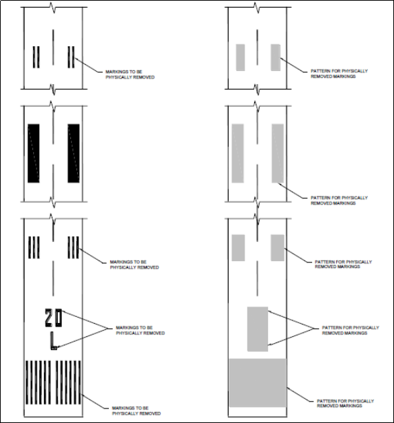
Figure 1
AMC1 ADR.OPS.C.015(d);(f) Maintenance of visual aids and electrical systems
ED Decision 2021/003/R
MARKINGS AND SIGNS
(a) Markings
A system of preventive maintenance of visual aids should be employed to ensure marking system reliability, both day and night. All markings should be inspected thoroughly at least semiannually, depending on local weather conditions, and corrective action should be taken in case of need, such as peeling, discolourment, fading, or accumulation of deposits.
(b) Signs
Maintenance should ensure integrity and perfect legibility of the information provided by the signs. Checks for each sign should be both scheduled (daily, annual) and unscheduled, and should take into account the instructions of the manufacturer.
GM1 ADR.OPS.C.015(d);(f) Maintenance of visual aids and electrical systems
ED Decision 2021/003/R
MARKINGS AND SIGNS
(a) An assessment of the condition of the signs and markings performed during the night when compared with an assessment performed during the daylight, allows determining the reflectivity of the marking. Therefore, the maintenance programme takes due account of this.
(b) Daily checks of signs need to focus on the functioning of the lamps, the legibility of inscriptions, damage to the sign panels, fading of the colours, and the removal of possible obstructions. During night inspections, the proper illumination of the signs is also checked.
(c) Annual checks of signs include:
(1) the mounting of both the sign and its lighting; and
(2) the sign’s structure.
(d) Unscheduled checks are necessary after weather phenomena that may affect the functioning of a sign, such as snowfalls to remove snow accumulation, storms that may have damaged the signs, etc.