ED Decision 2011/012/R
Strength requirements are specified in terms of:
(a) limit loads that are the maximum loads to be expected in service, taking into account the load factors of CS 31GB.23; and
(b) ultimate loads that are limit loads multiplied by factors of safety of CS 31GB.25.
ED Decision 2011/012/R
Flight load factor. In determining limit loads, the load factor must be at least 1·4.
ED Decision 2011/012/R
(a) A factor of safety must be used in the balloon design as provided in the table.
|
|
Safety factor |
|
Envelope |
5·00 |
|
Suspension components (fibrous or non-metallic) |
2·25 |
|
Suspension components (metallic) |
1·50 |
|
Other |
1·50 |
(b) The primary attachments of the envelope to the basket must be designed so that any single failure will not jeopardise safety of flight.
(c) For design purposes, an occupant mass of at least 77 kg must be assumed.
ED Decision 2011/012/R
The term ‘envelope’ here includes the integral vertical and horizontal load tapes as well as the envelope fabric(s). It should be noted that the suspension system pick-up points (sometimes known as ‘turnbacks’) at the envelope should be regarded as part of the suspension system, rather than the envelope, as far as 31GB.25 is concerned.
‘Suspension components’ here are those parts of the balloon that carry the load between the lift force of the envelope and the weight force of the basket.
A net around the envelope taking these loads or suspension system pick-up points should be considered as part of the suspension system.
The individual structural elements in the suspension system should be dimensioned and configured or duplicated so that failure or absence of one structural element does not cause any uncontrollable operating condition. The factors of safety apply to all parts of the load bearing path (e.g. joints, splices, knots, terminals, etc.).
The post-single failure case only needs to be justified with the application of limit loads.
CS 31GB.27 Strength and proof of strength
ED Decision 2011/012/R
(a) The structure must be able to support limit loads without permanent deformations or other detrimental effects.
(b) The structure must be able to withstand ultimate loads for at least 3 seconds without failure.
(c) Proof of strength of the envelope material and other critical design features must be tested.
(d) The basket must be of a generally robust design and afford the occupants adequate protection during a hard or fast landing. There must be no design feature that by reasonably envisaged distortion or failure would be likely to cause serious injury to the occupants.
(e) Each item of mass that could cause an unsafe condition if it broke loose must be restrained under all loads up to the ultimate loads specified in this paragraph. The local attachments in the load path between the restrains and the structure should be designed to withstand 1.33 times the specified ultimate loads
Horizontal 6 g,
Downward 6 g,
Upward 2 g.
(f) The design and strength of components must also consider the effects of recurrent and other loads experienced during transportation, ground handling and rigging.
(g) The effect of temperature and other operating characteristics that may affect strength of the balloon must be accounted for.
AMC 31GB.27 Strength and proof of strength
ED Decision 2011/012/R
Proof of compliance with the strength requirements must cover the balloon’s entire operating range. Proof by calculation only can be accepted for designs where it has been demonstrated by experience that such calculation gives reliable results. Load tests need to be performed in all other cases.
AMC 31GB.27(c) Strength and proof of strength
ED Decision 2011/012/R
The envelope tests may be performed on representative portions of the envelope provided the dimensions of these portions are sufficiently large to include critical design features and details such as critical seams, joints, load-attachment points, net mesh, etc. Also refer to CS 31GB.44 for specific tear propagation requirements.
AMC 31GB.27(d) Strength and proof of strength
ED Decision 2011/012/R
A drop test needs to be performed if it is not possible to make use of an existing proven basket of the same or similar design (in terms of construction method, size, layout, etc.) for a balloon of the size that is the subject of the application. In the absence of an alternative test proposal, this test must be performed at the maximum design mass of the basket in a manner that simulates the effects of gravity that occur as realistically as possible. The basket is dropped onto a horizontal concrete surface from a height of 1 m at 0°, 15° and 30°. The drop test should not result in deformation or fractures which, by their nature, could lead to the serious injury of occupants.
Note: It has been shown by a number of decades of in-service experience that the traditional reinforced woven wicker and willow basket design offers a combination of resilience and impact resistance that can contribute considerably to the protection of occupants. The structure is also able to absorb considerable kinetic energy during impact on the ground or against obstacles.
AMC 31GB.27(e) Strength and proof of strength
ED Decision 2011/012/R
Items of mass (e.g. batteries or equipment) inside the basket or attached to the suspension system near or above the occupants should be considered because of their risk to the occupants.
Items of mass that do not cause a risk to the occupants during a hard or fast landing, but could become detached from the balloon (e.g. ballast attached to the outside of the basket), should be considered because of the potential loss of mass.
AMC 31GB.27(f) Strength and proof of strength
ED Decision 2011/012/R
The strength requirements need to include consideration of loads during transport, ground handling and rigging. The loads need to be determined and the parts and components need to be designed in accordance with their designated use and dimensioned such as not to fail under recurrent loads.
CS 31GB.28 Tethered flight loads
ED Decision 2011/012/R
(a) The effects of the loads associated with tethered flight on the balloon’s components and any additional equipment (if required) must be considered in the design.
(b) The tethered restraint system must be designed so that any single failure will not jeopardise the safety of the occupants, the balloon and or third parties.
(c) Operational limitations, associated to tethered flight, must be established and recorded in the Flight Manual. (See CS 31GB.81(b)(2))
AMC 31GB.28(a) Tethered Flight Loads
ED Decision 2011/012/R
Due to the complexity of tethered flight loading, a simple analysis using configurations based on industry best practice (e.g. restraints/tether lines in a ‘flat tripod’ configuration with upwind and downwind v-bridles) can be used to determine the suitability of a design.
The structure needs to be designed so that stress concentrations beyond the limit of fatigue are avoided in areas where normal operation may produce varying stress.
Note: The greatest danger during tethering is if any element of the tethering equipment should fail with insufficient positive buoyancy for safe free flight. For this reason, a single point/single element tethering should not be considered.
ED Decision 2011/012/R
(a) When an occupant restraint harness is installed, the harness must not fail when subjected to loads resulting from the occupant mass submitted to the following acceleration (See Figure 1):
(1) 2·0g Upwards
(2) 3·0g Horizontally in all directions.
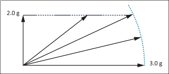
 Figure 1: Restraint harness loads
An occupant mass of at least 86 kg must be assumed for the purposes of this paragraph.
(b) Local attachments in the load path between the safety belt or harness and the main structure of the basket, restraining the occupant, must be shown to be able to withstand the loads prescribed in CS 31GB.30(a) multiplied by a fitting factor of 1·33.