
CAT.OP.MPA.100 Use of air traffic services
Regulation (EU) 2021/1296
(a) The operator shall ensure that:
(1) air traffic services (ATS) appropriate to the airspace and the applicable rules of the air are used for all flights whenever available;
(2) in-flight operational instructions involving a change to the ATS flight plan, when practicable, are coordinated with the appropriate ATS unit before transmission to an aircraft.
(b) Notwithstanding (a), the use of ATS is not required unless mandated by air space requirements for:
(1) operations under VFR by day of other-than complex motor-powered aeroplanes;
(2) helicopters with an MCTOM of 3 175 kg or less operated by day and over routes navigated by reference to visual landmarks; or
(3) local helicopter operations (LHOs),
provided that search and rescue service arrangements can be maintained.
IN-FLIGHT OPERATIONAL INSTRUCTIONS
When coordination with an appropriate air traffic service (ATS) unit has not been possible, in-flight operational instructions do not relieve a commander of the responsibility for obtaining an appropriate clearance from an ATS unit, if applicable, before making a change in flight plan.
CAT.OP.MPA.101 Altimeter check and settings
Regulation (EU) 2021/2237
(a) The operator shall establish procedures for altimeter checking before each departure.
(b) The operator shall establish procedures for altimeter settings for all phases of flight, which shall take into account the procedures established by the State of the aerodrome or the State of the airspace, if applicable.
GM1 CAT.OP.MPA.101(b) Altimeter check and settings
ED Decision 2022/014/R
ALTIMETER SETTING PROCEDURES
The following paragraphs of ICAO Doc 8168 (PANS-OPS), Volume III provide recommended guidance on how to develop the altimeter setting procedure:
(a) 3.2 ‘Pre-flight operational test’;
(b) 3.3 ‘Take-off and climb’;
(c) 3.5 ‘Approach and landing’.
CAT.OP.MPA.105 Use of aerodromes and operating sites
Regulation (EU) 2015/140
(a) The operator shall only use aerodromes and operating sites that are adequate for the type(s) of aircraft and operation(s) concerned.
(b) The use of operating sites shall only apply to:
(1) other-than complex motor-powered aeroplanes; and
(2) helicopters.
DEFINING OPERATING SITES — HELICOPTERS
When defining operating sites (including infrequent or temporary sites) for the type(s) of helicopter(s) and operation(s) concerned, the operator should take account of the following:
(a) An adequate site is a site that the operator considers to be satisfactory, taking account of the applicable performance requirements and site characteristics (guidance on standards and criteria are contained in ICAO Annex 14 Volume 2 and in the ICAO Heliport Manual (Doc 9261-AN/903)).
(b) The operator should have in place a procedure for the survey of sites by a competent person. Such a procedure should take account of possible changes to the site characteristics which may have taken place since last surveyed.
(c) Sites that are pre-surveyed should be specifically specified in the operations manual. The operations manual should contain diagrams or/and ground and aerial photographs, and depiction (pictorial) and description of:
(1) the overall dimensions of the site;
(2) location and height of relevant obstacles to approach and take-off profiles, and in the manoeuvring area;
(3) approach and take-off flight paths;
(4) surface condition (blowing dust/snow/sand);
(5) helicopter types authorised with reference to performance requirements;
(6) provision of control of third parties on the ground (if applicable);
(7) procedure for activating site with land owner or controlling authority;
(8) other useful information, for example, appropriate ATS agency and frequency; and
(9) lighting (if applicable).
(d) For sites that are not pre-surveyed, the operator should have in place a procedure that enables the pilot to make, from the air, a judgment on the suitability of a site. (c)(1) to (c)(6) should be considered.
(e) Operations to non-pre-surveyed sites by night (except in accordance with SPA.HEMS.125(b)(4)) should not be permitted.
[applicable until 24 May 2024 — ED Decision 2014/015/R]
(e) Operations to non-pre-surveyed sites by night (except in accordance with SPA.HEMS.125(c)(4)) should not be permitted.
CAT.OP.MPA.107 Adequate aerodrome
Regulation (EU) 2021/2237
The operator shall consider an aerodrome as adequate if, at the expected time of use, the aerodrome is available and equipped with necessary ancillary services such as air traffic services (ATS), sufficient lighting, communications, meteorological reports, navigation aids and emergency services.
AMC1 CAT.OP.MPA.107 Adequate aerodrome
ED Decision 2019/019/R
RESCUE AND FIREFIGHTING SERVICES (RFFS)
When considering the adequacy of an aerodrome’s rescue and firefighting services (RFFS), the operator should:
(a) as part of its management system, assess the level of RFFS protection available at the aerodrome intended to be specified in the operational flight plan in order to ensure that an acceptable level of protection is available for the intended operation; and
(b) include relevant information related to the RFFS protection that is deemed acceptable by the operator in the operations manual.
GM1 CAT.OP.MPA.107 Adequate aerodrome
ED Decision 2022/005/R
VERIFICATION OF WEATHER CONDITIONS
This GM clarifies the difference between ‘adequate aerodrome’ and ‘weather-permissible aerodrome’. The two concepts are complementary:
— ‘adequate aerodrome’: see definition in Annex I (Definitions for terms used in Annexes II to VIII) and point CAT.OP.MPA.107 of Annex IV (Part-CAT) to Regulation (EU) No 965/2012; and
— ‘weather-permissible aerodrome’ means an adequate aerodrome with additional requirements: see definition in Annex I (Definitions for terms used in Annexes II to VIII).
Weather conditions are not required to be considered at an adequate aerodrome.
CAT.OP.MPA.110 Aerodrome operating minima
Regulation (EU) 2021/2237
(a) The operator shall establish aerodrome operating minima for each departure, destination or alternate aerodrome that is planned to be used in order to ensure separation of the aircraft from terrain and obstacles and to mitigate the risk of loss of visual references during the visual flight segment of instrument approach operations.
(b) The method used to establish aerodrome operating minima shall take all the following elements into account:
(1) the type, performance, and handling characteristics of the aircraft;
(2) the equipment available on the aircraft for the purpose of navigation, acquisition of visual references, and/or control of the flight path during take-off, approach, landing, and the missed approach;
(3) any conditions or limitations stated in the aircraft flight manual (AFM);
(4) the relevant operational experience of the operator;
(5) the dimensions and characteristics of the runways/final approach and take-off areas (FATOs) that may be selected for use;
(6) the adequacy and performance of the available visual and non-visual aids and infrastructure;
(7) the obstacle clearance altitude/height (OCA/H) for the instrument approach procedures (IAPs);
(8) the obstacles in the climb-out areas and necessary clearance margins;
(9) the composition of the flight crew, their competence and experience;
(10) the IAP;
(11) the aerodrome characteristics and the available air navigation services (ANS);
(12) any minima that may be promulgated by the State of the aerodrome;
(13) the conditions prescribed in the operations specifications including any specific approvals for low-visibility operations (LVOs) or operations with operational credits.
(14) any non-standard characteristics of the aerodrome, the IAP or the environment
(c) The operator shall specify a method of determining aerodrome operating minima in the operations manual.
(d) The method used by the operator to establish aerodrome operating minima and any change to that method shall be approved by the competent authority.
TAKE-OFF OPERATIONS — AEROPLANES
(a) Take-off minima
Take-off minima should be expressed as visibility (VIS) or runway visual range (RVR) limits, taking into account all relevant factors for each runway planned to be used and aircraft characteristics and equipment. Where there is a specific need to see and avoid obstacles on departure and/or for a forced landing, additional conditions, e.g. ceiling, should be specified.
(b) Visual reference
(1) The take-off minima should be selected to ensure sufficient guidance to control the aircraft in the event of both a rejected take-off in adverse circumstances and a continued take-off after failure of the critical engine.
(2) For night operations, the prescribed runway lights should be in operation.
(c) Required RVR or VIS
(1) For multi-engined aeroplanes, with performance such that, in the event of a critical engine failure at any point during take-off, the aeroplane can either stop or continue the take-off to a height of 1 500 ft above the aerodrome while clearing obstacles by the required margins, the take-off minima specified by the operator should be expressed as RVR or VIS values not lower than those specified in Table 1.
(2) For multi-engined aeroplanes without the performance to comply with the conditions in (c)(1), in the event of a critical engine failure, there may be a need to re-land immediately and to see and avoid obstacles in the take-off area. Such aeroplanes may be operated to the following take-off minima provided that they are able to comply with the applicable obstacle clearance criteria, assuming engine failure at the height specified. The take-off minima specified by the operator should be based upon the height from which the one-engine-inoperative (OEI) net take-off flight path can be constructed. The RVR minima used should not be lower than either of the values specified in Table 1 or Table 2.
(3) For single-engined turbine aeroplane operations approved in accordance with Subpart L (SET-IMC) of Annex V (Part-SPA), the take-off minima specified by the operator should be expressed as RVR values not lower than those specified in Table 1.
Unless the operator is making use of a risk period, whenever the surface in front of the runway does not allow for a safe forced landing, the RVR values should not be lower than 800 m. In this case, the proportion of the flight to be considered starts at the lift-off position and ends when the aeroplane is able to turn back and land on the runway in the opposite direction or glide to the next landing site in case of power loss.
Table 1
Take-off — aeroplanes (without LVTO approval)
RVR or VIS
|
Minimum RVR* or VIS* |
Facilities |
|
500 m (day) |
Nil** |
|
400 m (day) |
Centre line markings or Runway edge lights or Runway centre line lights |
|
400 m (night) |
Runway end lights*** and Runway edge lights or runway centreline lights |
* The reported RVR or VIS value representative of the initial part of the take-off run can be replaced by pilot assessment.
** The pilot is able to continuously identify the take-off surface and maintain directional control.
*** Runway end lights may be substituted by colour-coded runway edge lights or colour-coded runway centre line lights.
Table 2
Take-off — aeroplanes (without LVTO approval)
Assumed engine failure height above the runway versus RVR or VIS
|
Assumed engine failure height above the take-off runway (ft) |
RVR or VIS (m)** |
|
<50 |
400 |
|
51–100 |
400 |
|
101–150 |
400 |
|
151–200 |
500 |
|
201–300 |
1 000 |
|
>300* or if no positive take-off flight path can be constructed |
1 500 |
** The reported RVR or VIS value representative of the initial part of the take-off run can be replaced by pilot assessment.
TAKE-OFF OPERATIONS — HELICOPTERS
(a) General
(1) Take-off minima should be expressed as VIS or RVR limits, taking into account all relevant factors for each aerodrome or operating site planned to be used and aircraft characteristics and equipment. Where there is a specific need to see and avoid obstacles on departure, or for a forced landing, additional conditions, e.g. ceiling, should be specified.
(2) The commander should not commence take-off unless the meteorological conditions at the aerodrome or operating site of departure are equal to or better than the applicable minima for landing at that aerodrome or operating site unless a weather-permissible take-off alternate aerodrome is available.
(3) When the reported VIS is below that required for take-off and the RVR is not reported, a take-off should only be commenced if the commander can determine that the visibility or RVR along the take-off runway/area is equal to or better than the required minimum.
(4) When no reported VIS or RVR is available, a take-off should only be commenced if the commander can determine that the visibility along the take-off runway/area is equal to or better than the required minimum.
(b) Visual reference
(1) The take-off minima should be selected to ensure sufficient guidance to control the aircraft in the event of both a rejected take-off in adverse circumstances and a continued take-off after failure of the critical engine.
(2) For night operations, ground lights should be available to illuminate the take-off runway/final approach and take-off area (FATO) and any obstacles.
(3) For point-in-space (PinS) departures to an initial departure fix (IDF), the take-off minima should be selected to ensure sufficient guidance to see and avoid obstacles and return to the heliport if the flight cannot be continued visually to the IDF. This should require a VIS of 800 m. The ceiling should be 250 ft.
(c) Required RVR or VIS
(1) For performance class 1 operations, the operator should specify an RVR or a VIS as take‑off minima in accordance with Table 3.
(2) For performance class 2 operations onshore, the commander should operate to take-off minima of 800 m RVR or VIS and remain clear of cloud during the take-off manoeuvre until reaching performance class 1 capabilities.
(3) For performance class 2 operations offshore, the commander should operate to minima not less than those for performance class 1 and remain clear of cloud during the take-off manoeuvre until reaching performance class 1 capabilities.
Table 3
Take-off — helicopters (without LVTO approval)
RVR or VIS
|
Onshore aerodromes with instrument flight rules (IFR) departure procedures |
RVR or VIS (m)** |
|
No light and no markings (day only) |
400 or the rejected take-off distance, whichever is the greater |
|
No markings (night) |
800 |
|
Runway edge/FATO light and centre line marking |
400 |
|
Runway edge/FATO light, centre line marking and relevant RVR information |
400 |
|
Offshore helideck* |
|
|
Two-pilot operations |
400 |
|
Single-pilot operations |
500 |
* The take-off flight path to be free of obstacles.
** On PinS departures to IDF, VIS should not be less than 800 m and the ceiling should not be less than 250 ft.
DETERMINATION OF DH/MDH FOR INSTRUMENT APPROACH OPERATIONS — AEROPLANES
(a) The decision height (DH) to be used for a 3D approach operation or a 2D approach operation flown using the continuous descent final approach (CDFA) technique should not be lower than the highest of:
(1) the obstacle clearance height (OCH) for the category of aircraft;
(2) the published approach procedure DH or minimum descent height (MDH) where applicable;
(3) the system minima specified in Table 4;
(4) the minimum DH permitted for the runway specified in Table 5; or
(5) the minimum DH specified in the aircraft flight manual (AFM) or equivalent document, if stated.
(b) The MDH for a 2D approach operation flown not using the CDFA technique should not be lower than the highest of:
(1) the OCH for the category of aircraft;
(2) the published approach procedure MDH where applicable;
(3) the system minima specified in Table 4;
(4) the lowest MDH permitted for the runway specified in Table 5; or
(5) the lowest MDH specified in the AFM, if stated.
System minima — aeroplanes
|
Lowest DH/MDH (ft) |
|
|
ILS/MLS/GLS |
200 |
|
GNSS/SBAS (LPV) |
200* |
|
Precision approach radar (PAR) |
200 |
|
GNSS/SBAS (LP) |
250 |
|
GNSS (LNAV) |
250 |
|
GNSS/Baro VNAV (LNAV/VNAV) |
250 |
|
LOC with or without DME |
250 |
|
SRA (terminating at ½ NM) |
250 |
|
SRA (terminating at 1 NM) |
300 |
|
SRA (terminating at 2 NM or more) |
350 |
|
VOR |
300 |
|
VOR/DME |
250 |
|
NDB |
350 |
|
NDB/DME |
300 |
|
VDF |
350 |
* For localiser performance with vertical guidance (LPV), a DH of 200 ft may be used only if the published FAS datablock sets a vertical alert limit not exceeding 35 m. Otherwise, the DH should not be lower than 250 ft.
Table 5
Runway type minima — aeroplanes
|
Runway type |
Lowest DH/MDH (ft) |
|
|
Instrument runway |
Precision approach (PA) runway, category I |
200 |
|
NPA runway |
250 |
|
|
Non-Instrument runway |
Non-instrument runway |
Circling minima as shown in Table 15 |
(c) Where a barometric DA/H or MDA/H is used, this should be adjusted where the ambient temperature is significantly below international standard atmosphere (ISA). GM8 CAT.OP.MPA.110 ‘Low temperature correction’ provides a cold temperature correction table for adjustment of minimum promulgated heights/altitudes.
AMC4 CAT.OP.MPA.110 Aerodrome operating minima
ED Decision 2022/012/R
DETERMINATION OF DH/MDH FOR INSTRUMENT APPROACH OPERATIONS — HELICOPTERS
(a) The DH or MDH to be used for a 3D or a 2D approach operation should not be lower than the highest of:
(1) the OCH for the category of aircraft;
(2) the published approach procedure DH or MDH where applicable;
(3) the system minima specified in Table 6;
(4) the minimum DH permitted for the runway/FATO specified in Table 7, if applicable; or
(5) the minimum DH specified in the AFM or equivalent document, if stated.
Table 6
System minima — helicopters
|
Facility |
Lowest DH/MDH (ft) |
|
ILS/MLS/GLS |
200 |
|
GNSS/SBAS (LPV)* |
200 |
|
Precision approach radar (PAR) |
200 |
|
GNSS/SBAS (LP) |
250 |
|
GNSS (LNAV) |
250 |
|
GNSS/Baro VNAV (LNAV/VNAV) |
250 |
|
Helicopter PinS approach |
250** |
|
LOC with or without DME |
250 |
|
SRA (terminating at ½ NM) |
250 |
|
SRA (terminating at 1 NM) |
300 |
|
SRA (terminating at 2 NM or more) |
350 |
|
VOR |
300 |
|
VOR/DME |
250 |
|
NDB |
350 |
|
NDB/DME |
300 |
|
VDF |
350 |
* For LPV, a DH of 200 ft may be used only if the published FAS datablock sets a vertical alert limit not exceeding 35 m. Otherwise, the DH should not be lower than 250 ft.
** For PinS approaches with instructions to ‘proceed VFR’ to an undefined or virtual destination, the DH or MDH should be with reference to the ground below the missed approach point (MAPt).
Table 7
Type of runway/FATO versus lowest DH/MDH — helicopters
|
Type of runway/FATO |
Lowest DH/MDH (ft) |
|
Precision approach (PA) runway, category I Non-precision approach (NPA) runway Non-instrument runway |
200 |
|
Instrument FATO FATO |
200 250 |
Table 7 does not apply to helicopter PinS approaches with instructions to ‘proceed VFR’.
AMC5 CAT.OP.MPA.110 Aerodrome operating minima
ED Decision 2023/007/R
DETERMINATION OF RVR OR VIS FOR INSTRUMENT APPROACH OPERATIONS — AEROPLANES
(a) The RVR or VIS for straight-in instrument approach operations should be not less than the greatest of:
(1) the minimum RVR or VIS for the type of runway used according to Table 8;
(2) the minimum RVR determined according to the MDH or DH and class of lighting facility according to Table 9; or
(3) the minimum RVR according to the visual and non-visual aids and on-board equipment used according to Table 10.
If the value determined in (1) is a VIS, then the result is a minimum VIS. In all other cases, the result is a minimum RVR.
(b) For Category A and B aeroplanes, if the RVR or VIS determined in accordance with (a) is greater than 1 500 m, then 1 500 m should be used.
(c) If the approach is flown with a level flight segment at or above the MDA/H, then 200 m should be added to the RVR calculated in accordance with (a) and (b) for Category A and B aeroplanes and 400 m for Category C and D aeroplanes.
Table 8
Type of runway versus minimum RVR or VIS — aeroplanes
|
Type of runway |
Minimum RVR or VIS (m) |
|
PA runway Category I |
RVR 550 |
|
NPA runway |
RVR 750 |
|
Non-instrument runway |
VIS according to Table 15 (circling minima) |
Table 9
RVR versus DH/MDH — aeroplanes
|
DH or MDH (ft) |
Class of lighting facility |
|||||
|
FALS |
IALS |
BALS |
NALS |
|||
|
RVR (m) |
||||||
|
200 |
- |
210 |
550 |
750 |
1 000 |
1 200 |
|
211 |
- |
240 |
550 |
800 |
1 000 |
1 200 |
|
241 |
- |
250 |
550 |
800 |
1 000 |
1 300 |
|
251 |
- |
260 |
600 |
800 |
1 100 |
1 300 |
|
261 |
- |
280 |
600 |
900 |
1 100 |
1 300 |
|
281 |
- |
300 |
650 |
900 |
1 200 |
1 400 |
|
301 |
- |
320 |
700 |
1 000 |
1 200 |
1 400 |
|
321 |
- |
340 |
800 |
1 100 |
1 300 |
1 500 |
|
341 |
- |
360 |
900 |
1 200 |
1 400 |
1 600 |
|
361 |
- |
380 |
1 000 |
1 300 |
1 500 |
1 700 |
|
381 |
- |
400 |
1 100 |
1 400 |
1 600 |
1 800 |
|
401 |
- |
420 |
1 200 |
1 500 |
1 700 |
1 900 |
|
421 |
- |
440 |
1 300 |
1 600 |
1 800 |
2 000 |
|
441 |
- |
460 |
1 400 |
1 700 |
1 900 |
2 100 |
|
461 |
- |
480 |
1 500 |
1 800 |
2 000 |
2 200 |
|
481 |
- |
500 |
1 500 |
1 800 |
2 100 |
2 300 |
|
501 |
- |
520 |
1 600 |
1 900 |
2 100 |
2 400 |
|
521 |
- |
540 |
1 700 |
2 000 |
2 200 |
2 400 |
|
541 |
- |
560 |
1 800 |
2 100 |
2 300 |
2 400 |
|
561 |
- |
580 |
1 900 |
2 200 |
2 400 |
2 400 |
|
581 |
- |
600 |
2 000 |
2 300 |
2 400 |
2 400 |
|
601 |
- |
620 |
2 100 |
2 400 |
2 400 |
2 400 |
|
621 |
- |
640 |
2 200 |
2 400 |
2 400 |
2 400 |
|
641 |
- |
660 |
2 300 |
2 400 |
2 400 |
2 400 |
|
and above |
2 400 |
2 400 |
2 400 |
2 400 |
||
Table 10
Visual and non-visual aids and/or on-board equipment versus minimum RVR — aeroplanes
|
Type of approach |
Facilities |
Lowest RVR |
|
|
Multi-pilot operations |
Single-pilot operations |
||
|
3D operations
Final approach track offset ≤15° for category A and B aeroplanes or ≤5° for Category C and D aeroplanes |
runway touchdown zone lights (RTZL) and runway centre line lights (RCLL) |
No limitation |
|
|
without RTZL and/or RCLL but using HUDLS or equivalent system; without RTZL and/or RCLL but using autopilot or flight director to the DH |
No limitation |
600 m |
|
|
No RTZL and/or RCLL, not using HUDLS or equivalent system or autopilot or flight director to the DH |
750 m |
800 m |
|
|
3D operations |
runway touchdown zone lights (RTZL) and runway centre line lights (RCLL) and Final approach track offset >15° for Category A and B aeroplanes or Final approach track offset > 5° for Category C and D aeroplanes |
800 m |
1 000 m |
|
without RTZL and RCLL but using HUDLS or equivalent system; autopilot or flight director to the DH and Final approach track offset > 15° for Category A and B aeroplanes or Final approach track offset > 5° for Category C and D aeroplanes |
800 m |
1 000 m |
|
|
2D operations |
Final approach track offset ≤15° for category A and B aeroplanes or ≤5° for Category C and D aeroplanes |
750 m |
800 m |
|
Final approach track offset 15° for Category A and B aeroplanes |
1 000 m |
1 000 m |
|
|
Final approach track offset 5° for Category C and D aeroplanes |
1 200 m |
1 200 m |
|
Table 11
Approach lighting systems — aeroplanes
|
Class of lighting facility |
Length, configuration and intensity of approach lights |
|
FALS |
CAT I lighting system (HIALS ≥720 m) distance coded centre line, barrette centre line |
|
IALS |
Simple approach lighting system (HIALS 420–719 m) single source, barrette |
|
BALS |
Any other approach lighting system (HIALS, MALS or ALS 210–419 m) |
|
NALS |
Any other approach lighting system (HIALS, MALS or ALS <210 m) or no approach lights |
(e) For night operations or for any operation where credit for visual aids is required, the lights should be on and serviceable except as provided for in Table 17.
(f) Where any visual or non-visual aid specified for the approach and assumed to be available in the determination of operating minima is unavailable, revised operating minima will need to be determined.
AMC6 CAT.OP.MPA.110 Aerodrome operating minima
ED Decision 2022/012/R
DETERMINATION OF RVR OR VIS FOR INSTRUMENT APPROACH OPERATIONS — HELICOPTERS
The RVR/VIS minima for Type A instrument approach and Type B CAT I instrument approach operations should be determined as follows:
(a) For IFR operations, the RVR or VIS should not be less than the greatest of:
(1) the minimum RVR or VIS for the type of runway/FATO used according to Table 12;
(2) the minimum RVR determined according to the MDH or DH and class of lighting facility according to Table 13; or
(3) for PinS operations with instructions to ‘proceed visually’, the distance between the MAPt of the PinS and the FATO or its approach light system.
If the value determined in (1) is a VIS, then the result is a minimum VIS. In all other cases, the result is a minimum RVR.
(b) For PinS operations with instructions to ‘proceed VFR’, the VIS should be compatible with visual flight rules.
(c) For Type A instrument approaches where the MAPt is within ½ NM of the landing threshold, the approach minima specified for FALS may be used regardless of the length of the approach lights available. However, FATO/runway edge lights, threshold lights, end lights and FATO/runway markings are still required.
(d) An RVR of less than 800 m should not be used except when using a suitable autopilot coupled to an ILS, an MLS, a GLS or LPV, in which case normal minima apply.
(e) For night operations, ground lights should be available to illuminate the FATO/runway and any obstacles.
(f) The visual aids should comprise standard runway day markings, runway edge lights, threshold lights and runway end lights and approach lights as specified in Table 14.
(g) For night operations or for any operation where credit for runway and approach lights as defined in Table 14 is required, the lights should be on and serviceable except as defined in Table 17.
Table 12
Type of runway/FATO versus minimum RVR — helicopters
|
Type of runway/FATO |
Minimum RVR or VIS |
|
PA runway, category I NPA runway Non-instrument runway |
RVR 550 m |
|
Instrument FATO FATO |
RVR 550 m RVR/VIS 800 m |
Table 13
Onshore helicopter instrument approach minima
|
DH/MDH (ft) |
Facilities versus RVR (m) |
|||
|
FALS |
IALS |
BALS |
NALS |
|
|
200 |
550 |
600 |
700 |
1 000 |
|
201–249 |
550 |
650 |
750 |
1 000 |
|
250–299 |
600* |
700* |
800 |
1 000 |
|
300 and above |
750* |
800 |
900 |
1 000 |
* Minima on 2D approach operations should be no lower than 800 m.
Table 14
Approach lighting systems — helicopters
|
Class of lighting facility |
Length, configuration and intensity of approach lights |
|
FALS |
CAT I lighting system (HIALS ≥ 720 m) distance coded centre line, barrette centre line |
|
IALS |
Simple approach lighting system (HIALS 420–719 m) single source, barrette |
|
BALS |
Any other approach lighting system (HIALS, MALS or ALS 210–419 m) |
|
NALS |
Any other approach lighting system (HIALS, MALS or ALS < 210 m) or no approach lights |
CIRCLING OPERATIONS — AEROPLANES
(a) Circling minima
The following standards should apply for establishing circling minima for operations with aeroplanes:
(1) the MDH for circling operation should not be lower than the highest of:
(i) the published circling OCH for the aeroplane category;
(ii) the minimum circling height derived from Table 15; or
(iii) the DH/MDH of the preceding instrument approach procedure (IAP);
(2) the MDA for circling should be calculated by adding the published aerodrome elevation to the MDH, as determined by (a)(1); and
(3) the minimum VIS for circling should be the higher of:
(i) the circling VIS for the aeroplane category, if published; or
(ii) the minimum VIS derived from Table 15.
Table 15
Circling — aeroplanes
MDH and minimum VIS versus aeroplane category
|
|
Aeroplane category |
|||
|
|
A |
B |
C |
D |
|
MDH (ft) |
400 |
500 |
600 |
700 |
|
Minimum VIS (m) |
1 500 |
1 600 |
2 400 |
3 600 |
(b) Conduct of flight — general
(1) the MDH and OCH included in the procedure are referenced to aerodrome elevation;
(2) the MDA is referenced to mean sea level;
(3) for these procedures, the applicable visibility is the VIS; and
(4) operators should provide tabular guidance of the relationship between height above threshold and the in-flight visibility required to obtain and sustain visual contact during the circling manoeuvre.
(c) Instrument approach followed by visual manoeuvring (circling) without prescribed tracks
(1) When the aeroplane is on the initial instrument approach, before visual reference is established, but not below MDA/H, the aeroplane should follow the corresponding IAP until the appropriate instrument MAPt is reached.
(2) At the beginning of the level flight phase at or above the MDA/H, the instrument approach track should be maintained until the pilot:
(i) estimates that, in all probability, visual contact with the runway of intended landing or the runway environment will be maintained during the entire circling procedure;
(ii) estimates that the aeroplane is within the circling area before commencing circling; and
(iii) is able to determine the aeroplane’s position in relation to the runway of intended landing with the aid of the appropriate visual references.
(3) If the pilot cannot comply with the conditions in (c)(2) at the MAPt, then a missed approach should be executed in accordance with the IAP.
(4) After the aeroplane has left the track of the initial instrument approach, the flight phase outbound from the runway should be limited to an appropriate distance, which is required to align the aeroplane onto the final approach. Such manoeuvres should be conducted to enable the aeroplane to:
(i) attain a controlled and stable descent path to the intended landing runway; and
(ii) remain within the circling area and in such way that visual contact with the runway of intended landing or runway environment is maintained at all times.
(5) Flight manoeuvres should be carried out at an altitude/height that is not less than the circling MDA/H.
(6) Descent below MDA/H should not be initiated until the threshold of the runway to be used has been appropriately identified. The aeroplane should be in a position to continue with a normal rate of descent and land within the touchdown zone (TDZ).
(d) Instrument approach followed by a visual manoeuvring (circling) with prescribed track
(1) The aeroplane should remain on the initial IAP until one of the following is reached:
(i) the prescribed divergence point to commence circling on the prescribed track; or
(ii) the MAPt.
(2) The aeroplane should be established on the instrument approach track in level flight at or above the MDA/H at or by the circling manoeuvre divergence point.
(3) If the divergence point is reached before the required visual reference is acquired, a missed approach should be initiated not later than the MAPt and completed in accordance with the instrument approach procedure.
(4) When commencing the prescribed circling manoeuvre at the published divergence point, the subsequent manoeuvres should be conducted to comply with the published routing and published heights/altitudes.
(5) Unless otherwise specified, once the aeroplane is established on the prescribed track(s), the published visual reference does not need to be maintained unless:
(i) required by the State of the aerodrome; or
(ii) the circling MAPt (if published) is reached.
(6) If the prescribed circling manoeuvre has a published MAPt and the required visual reference has not been obtained by that point, a missed approach should be executed in accordance with (e)(2) and (e)(3).
(7) Subsequent further descent below MDA/H should only commence when the required visual reference has been obtained.
(8) Unless otherwise specified in the procedure, final descent should not be commenced from MDA/H until the threshold of the intended landing runway has been identified and the aeroplane is in a position to continue with a normal rate of descent to land within the TDZ.
(e) Missed approach
(1) Missed approach during the instrument procedure prior to circling
(i) If the missed approach procedure is required to be flown when the aeroplane is positioned on the instrument approach track defined by radio-navigation aids RNAV, RNP, or ILS, MLS, and before commencing the circling manoeuvre, the published missed approach for the instrument approach should be followed; or
(ii) If the IAP is carried out with the aid of an ILS, an MLS or a stabilised approach (SAp), the MAPt associated with an ILS or an MLS procedure without glide path (GP-out procedure) or the SAp, where applicable, should be used.
(2) If a prescribed missed approach is published for the circling manoeuvre, this overrides the manoeuvres prescribed below.
(3) If visual reference is lost while circling to land after the aeroplane has departed from the initial instrument approach track, the missed approach specified for that particular instrument approach should be followed. It is expected that the pilot will make an initial climbing turn toward the intended landing runway to a position overhead the aerodrome where the pilot will establish the aeroplane in a climb on the instrument missed approach segment.
(4) The aeroplane should not leave the visual manoeuvring (circling) area, which is obstacle-protected, unless:
(i) established on the appropriate missed approach procedure; or
(ii) at minimum sector altitude (MSA).
(5) All turns should be made in the same direction and the aeroplane should remain within the circling protected area while climbing either:
(i) to the altitude assigned to any published circling missed approach manoeuvre if applicable;
(ii) to the altitude assigned to the missed approach of the initial instrument approach;
(iii) to the MSA; or
(iv) to the minimum holding altitude (MHA) applicable to transition to a holding facility or fix, or continue to climb to an MSA;
or as directed by ATS.
When the missed approach procedure is commenced on the ‘downwind’ leg of the circling manoeuvre, an ‘S’ turn may be undertaken to align the aeroplane on the initial instrument approach missed approach path, provided the aeroplane remains within the protected circling area.
The commander should be responsible for ensuring adequate terrain clearance during the above-stipulated manoeuvres, particularly during the execution of a missed approach initiated by ATS.
(6) Because the circling manoeuvre may be accomplished in more than one direction, different patterns will be required to establish the aeroplane on the prescribed missed approach course depending on its position at the time visual reference is lost. In particular, all turns are to be in the prescribed direction if this is restricted, e.g. to the west/east (left or right hand) to remain within the protected circling area.
(7) If a missed approach procedure is published for a particular runway onto which the aeroplane is conducting a circling approach and the aeroplane has commenced a manoeuvre to align with the runway, the missed approach for this direction may be accomplished. The ATS unit should be informed of the intention to fly the published missed approach procedure for that particular runway.
(8) The commander should advise ATS when any missed approach procedure has been commenced, the height/altitude the aeroplane is climbing to and the position the aeroplane is proceeding towards and/or heading the aeroplane is established on.
ONSHORE CIRCLING OPERATIONS — HELICOPTERS
For circling, the specified MDH should not be less than 250 ft, and the VIS not less than 800 m.
VISUAL APPROACH OPERATIONS
The operator should not use an RVR of less than 800 m for a visual approach operation.
CONVERSION OF VISIBILITY TO CMV — AEROPLANES
The following conditions apply to the use of converted meteorological visibility (CMV) instead of RVR:
(a) If the reported RVR is not available, a CMV may be substituted for the RVR, except:
(1) to satisfy the take-off minima; or
(2) for the purpose of continuation of an approach in LVOs.
(b) If the minimum RVR for an approach is more than the maximum value assessed by the aerodrome operator, then CMV should be used.
(c) In order to determine CMV from visibility:
(1) for flight planning purposes, a factor of 1.0 should be used;
(2) for purposes other than flight planning, the conversion factors specified in Table 16 should be used.
Table 16
Conversion of reported VIS to RVR/CMV
|
Light elements in operation |
RVR/CMV = reported VIS x |
|
|
Day |
Night |
|
|
HI approach and runway lights |
1.5 |
2.0 |
|
Any type of light installation other than above |
1.0 |
1.5 |
|
No lights |
1.0 |
not applicable |
EFFECT ON LANDING MINIMA OF TEMPORARILY FAILED OR DOWNGRADED GROUND EQUIPMENT
(a) General
These instructions are intended for use both before and during flight. Only those facilities mentioned in Table 17 should be acceptable to be used to determine the effect of temporarily failed of downgraded equipment. It is, however, not expected that the commander would consult such instructions after passing 1 000 ft above the aerodrome. If failures of ground aids are announced at such a late stage, the approach could be continued at the commander’s discretion. If failures are announced before such a late stage in the approach, their effect on the approach should be considered as described in Table 17, and the approach may have to be abandoned.
(b) Conditions applicable to Table 17:
(1) multiple failures of runway/FATO lights other than those indicated in Table 17 should not be acceptable;
(2) failures of approach and runway/FATO lights are acceptable at the same time, and the most demanding consequence should be applied; and
(3) failures other than ILS, GLS, MLS affect the RVR only and not DH.
Table 17
Failed or downgraded equipment — effect on landing minima
Operations without LVO approval
|
Failed or downgraded equipment |
Effect on landing minima |
|
|
Type B |
Type A |
|
|
Navaid stand-by transmitter |
No effect |
|
|
Outer marker |
FOR CAT I: Not allowed except if the required height versus glide path can be checked using other means, e.g. DME fix |
APV — not applicable |
|
NPA with final approach fix (FAF): no effect unless used as FAF |
||
|
If the FAF cannot be identified (e.g. no method available for timing of descent), NPA operations cannot be conducted |
||
|
FOR CAT I: Not allowed except if the required height versus glide path can be checked using other means, e.g. DME fix |
||
|
Middle marker (ILS only) |
No effect |
No effect unless used as MAPt |
|
DME |
No effect if replaced by RNAV (GNSS) information or the outer marker |
|
|
RVR assessment systems |
No effect |
|
|
Approach lights |
Minima as for NALS |
|
|
Approach lights except the last 210 m |
Minima as for BALS |
|
|
Approach lights except the last 420 m |
Minima as for IALS |
|
|
Standby power for approach lights |
No effect |
|
|
Edge lights, threshold lights and runway end lights |
Day: no effect; |
|
|
Centre line lights |
Aeroplanes: No effect if flight director (F/D), HUDLS or autoland;
Helicopters: No effect on CAT I and HELI SA CAT I approach operations |
No effect but the minimum RVR should be 750m. |
|
Centre line lights spacing increased to 30 m |
No effect |
|
|
TDZ lights |
Aeroplanes: No effect if F/D, HUDLS or autoland;
Helicopters: No effect |
No effect |
|
Taxiway lighting system |
No effect |
|
VFR OPERATIONS WITH OTHER-THAN-COMPLEX MOTOR-POWERED AIRCRAFT
For the establishment of VFR operation minima, the operator may apply the VFR operating minima specified in Part-SERA. Where necessary, the operator may specify in the OM additional conditions for the applicability of such minima taking into account such factors as radio coverage, terrain, nature of sites for take-off and landing, flight conditions and ATS capacity.
ONSHORE AERODROME DEPARTURE PROCEDURES — HELICOPTERS
The cloud base and visibility should be such as to allow the helicopter to be clear of cloud at take-off decision point (TDP), and for the pilot flying to remain in sight of the surface until reaching the minimum speed for flight in instrument meteorological conditions (IMC) given in the AFM.
APPROACH LIGHTING SYSTEMS — ICAO, FAA
The following table provides a comparison of ICAO and FAA specifications.
Table 19
Approach lighting systems — ICAO and FAA specifications
|
Class of lighting facility |
Length, configuration and intensity of approach lights |
|
FALS |
ICAO: CAT I lighting system (HIALS ≥ 720 m) distance coded centre line, barrette centre line FAA: ALSF1, ALSF2, SSALR, MALSR, high or medium intensity and/or flashing lights, 720 m or more |
|
IALS |
ICAO: simple approach lighting system (HIALS 420–719 m) single source, barrette FAA: MALSF, MALS, SALS/SALSF, SSALF, SSALS, high or medium intensity and/or flashing lights, 420–719 m |
|
BALS |
Any other approach lighting system (HIALS, MALS or ALS 210–419 m) FAA: ODALS, high or medium intensity or flashing lights 210–419 m |
|
NALS |
Any other approach lighting system (HIALS, MALS or ALS <210 m) or no approach lights |
SBAS OPERATIONS
(a) SBAS LPV operations with a DH of 200 ft depend on an SBAS system approved for operations down to a DH of 200 ft.
(b) The following systems are in operational use or in a planning phase:
(1) European geostationary navigation overlay service (EGNOS) operational in Europe;
(2) wide area augmentation system (WAAS) operational in the USA;
(3) multi-functional satellite augmentation system (MSAS) operational in Japan;
(4) system of differential correction and monitoring (SDCM) planned by Russia;
(5) GPS aided geo augmented navigation (GAGAN) system, planned by India; and
(6) satellite navigation augmentation system (SNAS), planned by China.
GM4 CAT.OP.MPA.110 Aerodrome operating minima
ED Decision 2022/012/R
MEANS TO DETERMINE THE REQUIRED RVR BASED ON DH AND LIGHTING FACILITIES
The values in Table 9 are derived from the formula below:
Minimum RVR (m) = [(DH/MDH (ft) x 0.3048)/tanα] — length of approach lights (m)
where α is the calculation angle, being a default value of 3.00° increasing in steps of 0.10° for each line in Table 9 up to 3.77° and then remaining constant. An upper RVR limit of 2 400 m has been applied to the table.
GM5 CAT.OP.MPA.110 Aerodrome operating minima
ED Decision 2022/012/R
USE OF DH FOR NPAs FLOWN USING THE CDFA TECHNIQUE
AMC3 CAT.OP.MPA.110 provides that, in certain circumstances, a published MDH may be used as a DH for a 2D operation flown using the CDFA technique.
The safety of the use of MDH as DH in CDFA operations has been verified by at least two independent analyses concluding that the CDFA using MDH as DH without any add-on is safer than the traditional step-down and level-flight NPA operation. A comparison has been made between the safety level of using MDH as DH without an add-on with the well-established safety level resulting from the ILS collision risk model. The NPA used was the most demanding, i.e. most tightly designed NPA, which offers the least additional margins. It should be noted that the design limits of the ILS approach design, e.g. the maximum GP angle of 3,5 degrees, must be observed for the CDFA in order to keep the validity of the comparison.
There is a wealth of operational experience in Europe confirming the above-mentioned analytical assessments. It cannot be expected that each operator is able to conduct similar safety assessments, and this is not necessary. The safety assessments already performed take into account the most demanding circumstances at hand, like the most tightly designed NPA procedures and other ‘worst‑case scenarios’. The assessments naturally focus on cases where the controlling obstacle is located in the missed approach area.
However, it is necessary for operators to assess whether their cockpit procedures and training are adequate to ensure minimal height loss in case of a go-around manoeuvre. Suitable topics for the safety assessment required by each operator may include:
— understanding of the CDFA concept including the use of the MDA/H as DA/H;
— cockpit procedures that ensure flight on speed, on path and with proper configuration and energy management;
— cockpit procedures that ensure gradual decision-making; and
— identification of cases where an increase of the DA/H may be necessary because of non-standard circumstances, etc.
INCREMENTS SPECIFIED BY THE COMPETENT AUTHORITY
Additional increments to the published minima may be specified by the competent authority to take into account certain operations, such as downwind approaches, single-pilot operations or approaches flown not using the CDFA technique.
GM7 CAT.OP.MPA.110 Aerodrome operating minima
ED Decision 2022/012/R
USE OF COMMERCIALLY AVAILABLE INFORMATION
When an operator uses commercially available information to establish aerodrome operating minima, the operator remains responsible for ensuring that the material used is accurate and suitable for its operation, and that aerodrome operating minima are calculated in accordance with the method specified in Part C of its operations manual and approved by the competent authority.
The procedures in ORO.GEN.205 ‘Contracted activities’ apply in this case.
GM8 CAT.OP.MPA.110 Aerodrome operating minima
ED Decision 2023/007/R
LOW TEMPERATURE CORRECTION
(a) An operator may determine the aerodrome temperature below which a correction should be applied to the DA/H.
(b) Table 20 may be used to determine the correction that should be applied.
(c) The calculations in the table are for a sea-level aerodrome; they are therefore conservative when applied at higher-level aerodromes.
(d) Guidance on accurate corrections for specific conditions (if required) is available in PANS-OPS, Volume III (ICAO Doc 8168) Section 2 Chapter 4 First Edition, 2018.
Table 20
Temperature corrections to be applied to barometric DH/MDH
|
Aerodrome temperature |
Height above the elevation of the altimeter setting source (ft) |
|||||||||||||
|
200 |
300 |
400 |
500 |
600 |
700 |
800 |
900 |
1 000 |
1 500 |
2 000 |
3 000 |
4 000 |
5 000 |
|
|
0 |
20 |
20 |
30 |
30 |
40 |
40 |
50 |
50 |
60 |
90 |
120 |
170 |
230 |
280 |
|
-10 |
20 |
30 |
40 |
50 |
60 |
70 |
80 |
90 |
100 |
150 |
200 |
290 |
390 |
490 |
|
-20 |
30 |
50 |
60 |
70 |
90 |
100 |
120 |
130 |
140 |
210 |
280 |
420 |
570 |
710 |
|
-30 |
40 |
60 |
80 |
100 |
120 |
140 |
150 |
170 |
190 |
280 |
380 |
570 |
760 |
950 |
|
-40 |
50 |
80 |
100 |
120 |
150 |
170 |
190 |
220 |
240 |
360 |
480 |
720 |
970 |
1 210 |
|
-50 |
60 |
90 |
120 |
150 |
180 |
210 |
240 |
270 |
300 |
450 |
590 |
890 |
1 190 |
1 500 |
GM9 CAT.OP.MPA.110 Aerodrome operating minima
ED Decision 2022/012/R
AERODROME OPERATING MINIMA — HELICOPTERS
High vertical speeds should be avoided due to unstable aerodynamics and potential transient autorotation state of the main rotor.
Vertical speeds at or below 800 ft/min should be considered to be normal, and vertical speeds above 1 000 ft/min should be considered to be high.
The vertical speed on final approach increases with the descent angle and the ground speed (GS), including tailwinds. Whereas the helicopter should be manoeuvred into the wind during the visual segment of an instrument approach, tailwinds may be encountered during the instrument segments of the approach.
If the vertical speed is above 1 000 ft/min, a go-around should be considered. Greater vertical speeds may be used based on the available data in the rotorcraft flight manual.
Table 21 below gives an indication of the vertical speed based on the descent angles and ground speed.
Table 21
Examples of vertical speeds
|
Ground speed |
Descent angle |
Vertical speed |
|
80 kt |
5.7° (10 %) |
800 ft/min |
|
100 kt |
5.7° (10 %) |
1 000 ft/min |
|
80 kt |
7.5° (13.2 %) |
1 050 ft/min |
|
100 kt |
7.5° (13.2 %) |
1 300 ft/min |
Note: A GS of 80 kt may be the result of an indicated airspeed (IAS) of 60 kt and a tailwind component of 20 kt.
GM1 CAT.OP.MPA.110(b)(6) Aerodrome operating minima
ED Decision 2022/012/R
VISUAL AND NON-VISUAL AIDS AND INFRASTRUCTURE
‘Visual and non-visual aids and infrastructure’ refers to all equipment and facilities required for the procedure to be used for the intended instrument approach operation. This includes but is not limited to lights, markings, ground- or space-based radio aids, etc.
CAT.OP.MPA.115 Approach flight technique — aeroplanes
Regulation (EU) 2021/2237
(a) All approach operations shall be flown as stabilised approach operations unless otherwise approved by the competent authority for a particular approach to a particular runway.
(b) The continuous descent final approach (CDFA) technique shall be used for approach operations using non-precision approach (NPA) procedures except for such particular runways for which the competent authority has approved another flight technique.
CONTINUOUS DESCENT FINAL APPROACH (CDFA)
The following criteria apply to CDFA:
(a) For each NPA procedure to be used, the operator should provide information allowing the flight crew to determine the appropriate descent path. This information is either:
(1) a descent path depicted on the approach chart including check altitude/heights against range;
(2) a descent path coded into the aircraft flight management system; or
(3) a recommended descent rate based on estimated ground speed.
(b) The information provided to the crew should observe human factors principles.
(c) The descent path should be calculated to pass at or above the minimum altitude specified at any step-down fix.
(d) The optimum angle for the descent path is 3 and should not exceed 4,5 except for steep approach operations approved in accordance with this Part.
(e) For multi-pilot operations, the operator should establish procedures that require:
(1) the pilot monitoring to verbalise deviations from the required descent path;
(2) the pilot flying to make prompt corrections to deviation from the required descent path; and
(3) a call-out to be made when the aircraft is approaching the DA/H.
(f) A missed approach should be executed promptly at the DA/H or the MAPt, whichever is first, if the required visual references have not been established.
(g) For approaches other than circling approaches, the lateral part of the missed approach should be flown via the MAPt unless otherwise stated on the approach chart.
APPROACH OPERATIONS USING NPA PROCEDURES FLOWN WITH A FLIGHT TECHNIQUE OTHER THAN THE CDFA
(a) In case the CDFA technique is not used, the approach should be flown to an altitude/height at or above the MDA/H where a level flight segment at or above MDA/H may be flown to the MAPt.
(b) Even when the approach procedure is flown without the CDFA technique, the relevant procedures for ensuring a controlled and stable path to MDA/H should be followed.
(c) In case the CDFA technique is not used when flying an approach, the operator should implement procedures to ensure that early descent to the MDA/H will not result in a subsequent flight below MDA/H without adequate visual reference. These procedures could include:
(1) awareness of radio altimeter information with reference to the approach profile;
(2) terrain awareness warning system (TAWS);
(3) limitation of rate of descent;
(4) limitation of the number of repeated approaches;
(5) safeguards against too early descents with prolonged flight at MDA/H; and
(6) specification of visual requirements for the descent from the MDA/H.
(d) In case the CDFA technique is not used and when the MDA/H is high, it may be appropriate to make an early descent to MDA/H with appropriate safeguards such as the application of a significantly higher RVR or VIS.
(e) The procedures that are flown with level flight at or above the MDA/H should be listed in the OM.
(f) Operators should categorise aerodromes where there are approaches that require level flight at or above MDA/H as B or C. Such aerodrome categorisation will depend upon the operator’s experience, operational exposure, training programme(s) and flight crew qualification(s).
OPERATIONAL PROCEDURES AND INSTRUCTIONS AND TRAINING
(a) The operator should establish procedures and instructions for flying approaches using the CDFA technique and not using it. These procedures should be included in the operations manual and should include the duties of the flight crew during the conduct of such operations. The operator should ensure that the initial and recurrent flight crew training required by ORO.FC includes the use of the CDFA technique.
(b) Operators holding an approval to use another technique for NPAs on certain runways should establish procedures for the application of such techniques.
AMC1 CAT.OP.MPA.115(a) Approach flight technique — aeroplanes
ED Decision 2022/014/R
STABILISED APPROACH OPERATIONS — AEROPLANES
The following criteria should be satisfied for all stabilised approach operations with aeroplanes:
(a) The flight management systems and approach aids should be correctly set, and any required radio aids identified before reaching a predetermined point or altitude/height on the approach.
(b) The aeroplane should be flown according to the following criteria from a predetermined point or altitude/height on the approach:
(1) the angle of bank should be less than 30 degrees; and
(2) the target rate of descent should be that required to maintain the correct vertical path at the planned approach speed.
(c) Variations in the rate of descent should normally not exceed 50 % of the target rate of descent.
(d) An aeroplane should be considered stabilised for landing when the following conditions are met:
(1) the aeroplane is tracking within an acceptable tolerance of the required lateral path;
(2) the aeroplane is tracking within an acceptable tolerance of the required vertical path;
(3) the vertical speed of the aeroplane is within an acceptable tolerance of the required rate of descent;
(4) the airspeed of the aeroplane is within an acceptable tolerance of the intended landing speed;
(5) the aeroplane is in the correct configuration for landing, unless operating procedures require a final configuration change for performance reasons after visual reference is acquired; and
(6) the thrust/power and trim settings are appropriate.
(e) The aeroplane should be stabilised for landing before reaching 500 ft above the landing runway threshold elevation.
(f) For approach operations where the pilot does not have visual reference with the ground, the aeroplane should additionally be stabilised for landing before reaching 1 000 ft above the landing runway threshold elevation except that a later stabilisation in airspeed may be acceptable if higher than normal approach speeds are required for operational reasons specified in the operations manual.
(g) The operator should specify the following in the operations manual:
(1) the acceptable tolerances referred to in (d);
(2) the means to identify the predetermined points referred to in (a) and (b). This should normally be the FAF.
(h) When the operator requests approval for an alternative to the stabilised approach criteria for a particular approach to a particular runway, the operator should demonstrate that the proposed alternative will ensure that an acceptable level of safety is achieved.
GM1 CAT.OP.MPA.115(a) Approach flight techniques — aeroplanes
ED Decision 2022/012/R
ACCEPTABLE TOLERANCES FOR STABILISED APPROACH OPERATIONS
(a) The requirement for the aircraft to be tracking within an acceptable tolerance of the required lateral path does not imply that the aircraft has to be aligned with the runway centre line by any particular height.
(b) The target rate of descent for the final approach segment (FAS) of a stabilised approach normally does not exceed 1 000 fpm. Where a rate of descent of more than 1 000 fpm will be required (e.g. due to high ground speed or a steeper-than-normal approach path), this should be briefed in advance.
(c) Operational reasons for specifying a higher-than-normal approach speed below 1 000 ft may include compliance with air traffic control (ATC) speed restrictions.
(d) For operations where a level flight segment is required during the approach (e.g. circling approaches or approaches flown as non-CDFA), the criteria in point (b) of AMC1 CAT.OP.MPA.115(a) should apply from the predetermined point until the start of the level flight segment and again from the point at which the aircraft begins descent from the level flight segment down to a point of 50 ft above the threshold or the point where the flare manoeuvre is initiated, if higher.
CONTINUOUS DESCENT FINAL APPROACH (CDFA)
(a) Introduction
(1) Controlled flight into terrain (CFIT) is a major hazard in aviation. Most CFIT accidents occur in the FAS of approach operations flown using the NPA procedures. The use of stabilised-approach criteria on a continuous descent with a constant, predetermined vertical path is seen as a major improvement in safety during the conduct of such approaches.
(2) The elimination of level flight segments at MDA close to the ground during approaches, and the avoidance of major changes in attitude and power/thrust close to the runway that can destabilise approaches, are seen as ways to reduce operational risks significantly.
(3) The term CDFA has been selected to cover a flight technique for instrument approach operations using NPA procedures.
(4) The advantages of CDFA are as follows:
(i) the technique enhances safe approach operations by the utilisation of standard operating practices;
(ii) the technique is similar to that used when flying an ILS approach, including when executing the missed approach and the associated missed approach procedure manoeuvre;
(iii) the aeroplane attitude may enable better acquisition of visual cues;
(iv) the technique may reduce pilot workload;
(v) the approach profile is fuel-efficient;
(vi) the approach profile affords reduced noise levels;
(vii) the technique affords procedural integration with 3D approach operations; and
(viii) when used and the approach is flown in a stabilised manner, CDFA is the safest approach technique for all instrument approach operations using NPA procedures.
(b) Stabilised approach (SAp)
(1) The control of the descent path is not the only consideration when using the CDFA technique. Control of the aeroplane’s configuration and energy is also vital to the safe conduct of an approach.
(2) The control of the flight path, described above as one of the specifications for conducting an SAp, should not be confused with the path specifications for using the CDFA technique. The predetermined path specification for conducting an SAp are established by the operator and published in the operations manual.
(3) The appropriate descent path for applying the CDFA technique is established by the following:
(A) the published ‘nominal’ slope information when the approach has a nominal vertical profile; and
(B) the designated final-approach segment minimum of 3 NM, and maximum, when using timing techniques, of 8 NM.
(4) Straight-in approach operations using CDFA do not have a level segment of flight at MDA/H. This enhances safety by mandating a prompt missed approach procedure manoeuvre at DA/H.
(5) An approach using the CDFA technique is always flown as an SAp, since this is a specification for applying CDFA. However, an SAp does not have to be flown using the CDFA technique, for example, a visual approach.
(c) Circling approach operations using the CDFA technique
Circling approach operations using the CDFA technique require a continuous descent from an altitude/height at or above the FAF altitude/height until MDA/H or visual flight manoeuvre altitude/height. This does not preclude level flight at or above the MDA/H. This level flight may be at MDA/H while following the IAP or after visual reference has been established as the aircraft is aligned with the final approach track. The conditions for descent from level flight are described in AMC7 CAT.OP.MPA.110.
CAT.OP.MPA.125 Instrument departure and approach procedures
Regulation (EU) No 965/2012
(a) The operator shall ensure that instrument departure and approach procedures established by the State of the aerodrome are used.
(b) Notwithstanding (a), the commander may accept an ATC clearance to deviate from a published departure or arrival route, provided obstacle clearance criteria are observed and full account is taken of the operating conditions. In any case, the final approach shall be flown visually or in accordance with the established instrument approach procedures.
(c) Notwithstanding (a), the operator may use procedures other than those referred to in (a) provided they have been approved by the State in which the aerodrome is located and are specified in the operations manual.
CAT.OP.MPA.126 Performance-based navigation
Regulation (EU) 2016/1199
The operator shall ensure that, when performance-based navigation (PBN) is required for the route or procedure to be flown:
(a) the relevant PBN navigation specification is stated in the AFM or other document that has been approved by the certifying authority as part of an airworthiness assessment or is based on such approval; and
(b) the aircraft is operated in conformance with the relevant navigation specification and limitations in the AFM or other document referred above.
PBN OPERATIONS
For operations where a navigation specification for performance-based navigation (PBN) has been prescribed and no specific approval is required in accordance with SPA.PBN.100, the operator should:
(a) establish operating procedures specifying:
(1) normal, abnormal and contingency procedures;
(2) electronic navigation database management; and
(3) relevant entries in the minimum equipment list (MEL);
(b) specify the flight crew qualification and proficiency constraints and ensure that the training programme for relevant personnel is consistent with the intended operation; and
(c) ensure continued airworthiness of the area navigation system.
MONITORING AND VERIFICATION
(a) Preflight and general considerations
(1) At navigation system initialisation, the flight crew should confirm that the navigation database is current and verify that the aircraft position has been entered correctly, if required.
(2) The active flight plan, if applicable, should be checked by comparing the charts or other applicable documents with navigation equipment and displays. This includes confirmation of the departing runway and the waypoint sequence, reasonableness of track angles and distances, any altitude or speed constraints, and, where possible, which waypoints are fly-by and which are fly-over. Where relevant, the RF leg arc radii should be confirmed.
(3) The flight crew should check that the navigation aids critical to the operation of the intended PBN procedure are available.
(4) The flight crew should confirm the navigation aids that should be excluded from the operation, if any.
(5) An arrival, approach or departure procedure should not be used if the validity of the procedure in the navigation database has expired.
(6) The flight crew should verify that the navigation systems required for the intended operation are operational.
(b) Departure
(1) Prior to commencing a take-off on a PBN procedure, the flight crew should check that the indicated aircraft position is consistent with the actual aircraft position at the start of the take-off roll (aeroplanes) or lift-off (helicopters).
(2) Where GNSS is used, the signal should be acquired before the take-off roll (aeroplanes) or lift-off (helicopters) commences.
(3) Unless automatic updating of the actual departure point is provided, the flight crew should ensure initialisation on the runway or FATO by means of a manual runway threshold or intersection update, as applicable. This is to preclude any inappropriate or inadvertent position shift after take-off.
(c) Arrival and approach
(1) The flight crew should verify that the navigation system is operating correctly and the correct arrival procedure and runway (including any applicable transition) are entered and properly depicted.
(2) Any published altitude and speed constraints should be observed.
(3) The flight crew should check approach procedures (including alternate aerodromes if needed) as extracted by the system (e.g. CDU flight plan page) or presented graphically on the moving map, in order to confirm the correct loading and the reasonableness of the procedure content.
(4) Prior to commencing the approach operation (before the IAF), the flight crew should verify the correctness of the loaded procedure by comparison with the appropriate approach charts. This check should include:
(i) the waypoint sequence;
(ii) reasonableness of the tracks and distances of the approach legs and the accuracy of the inbound course; and
(iii) the vertical path angle, if applicable.
(d) Altimetry settings for RNP APCH operations using Baro VNAV
(1) Barometric settings
(i) The flight crew should set and confirm the correct altimeter setting and check that the two altimeters provide altitude values that do not differ more than 100 ft at the most at or before the final approach fix (FAF).
(ii) The flight crew should fly the procedure with:
(A) a current local altimeter setting source available — a remote or regional altimeter setting source should not be used; and
(B) the QNH/QFE, as appropriate, set on the aircraft’s altimeters.
(2) Temperature compensation
(i) For RNP APCH operations to LNAV/VNAV minima using Baro VNAV:
(A) the flight crew should not commence the approach when the aerodrome temperature is outside the promulgated aerodrome temperature limits for the procedure unless the area navigation system is equipped with approved temperature compensation for the final approach;
(B) when the temperature is within promulgated limits, the flight crew should not make compensation to the altitude at the FAF;
(C) since only the final approach segment is protected by the promulgated aerodrome temperature limits, the flight crew should consider the effect of temperature on terrain and obstacle clearance in other phases of flight.
(ii) For RNP APCH operations to LNAV minima, the flight crew should consider the effect of temperature on terrain and obstacle clearance in all phases of flight, in particular on any step-down fix.
(e) Sensor and lateral navigation accuracy selection
(1) For multi-sensor systems, the flight crew should verify, prior to approach, that the GNSS sensor is used for position computation.
(2) Flight crew of aircraft with RNP input selection capability should confirm that the indicated RNP value is appropriate for the PBN operation.
MANAGEMENT OF THE NAVIGATION DATABASE
(a) For RNAV 1, RNAV 2, RNP 1, RNP 2, and RNP APCH, the flight crew should neither insert nor modify waypoints by manual entry into a procedure (departure, arrival or approach) that has been retrieved from the database. User-defined data may be entered and used for waypoint altitude/speed constraints on a procedure where said constraints are not included in the navigation database coding.
(b) For RNP 4 operations, the flight crew should not modify waypoints that have been retrieved from the database. User-defined data (e.g. for flex-track routes) may be entered and used.
(c) The lateral and vertical definition of the flight path between the FAF and the missed approach point (MAPt) retrieved from the database should not be revised by the flight crew.
DISPLAYS AND AUTOMATION
(a) For RNAV 1, RNP 1, and RNP APCH operations, the flight crew should use a lateral deviation indicator, and where available, flight director and/or autopilot in lateral navigation mode.
(b) The appropriate displays should be selected so that the following information can be monitored:
(1) the computed desired path;
(2) aircraft position relative to the lateral path (cross-track deviation) for FTE monitoring;
(3) aircraft position relative to the vertical path (for a 3D operation).
(c) The flight crew of an aircraft with a lateral deviation indicator (e.g. CDI) should ensure that lateral deviation indicator scaling (full-scale deflection) is suitable for the navigation accuracy associated with the various segments of the procedure.
(d) The flight crew should maintain procedure centrelines unless authorised to deviate by air traffic control (ATC) or demanded by emergency conditions.
(e) Cross-track error/deviation (the difference between the area-navigation-system-computed path and the aircraft-computed position) should normally be limited to ± ½ time the RNAV/RNP value associated with the procedure. Brief deviations from this standard (e.g. overshoots or undershoots during and immediately after turns) up to a maximum of 1 time the RNAV/RNP value should be allowable.
(f) For a 3D approach operation, the flight crew should use a vertical deviation indicator and, where required by AFM limitations, a flight director or autopilot in vertical navigation mode.
(g) Deviations below the vertical path should not exceed 75 ft at any time, or half-scale deflection where angular deviation is indicated, and not more than 75 ft above the vertical profile, or half-scale deflection where angular deviation is indicated, at or below 1 000 ft above aerodrome level. The flight crew should execute a missed approach if the vertical deviation exceeds this criterion, unless the flight crew has in sight the visual references required to continue the approach.
VECTORING AND POSITIONING
(a) ATC tactical interventions in the terminal area may include radar headings, ‘direct to’ clearances which bypass the initial legs of an approach procedure, interceptions of an initial or intermediate segments of an approach procedure or the insertion of additional waypoints loaded from the database.
(b) In complying with ATC instructions, the flight crew should be aware of the implications for the navigation system.
(c) ‘Direct to’ clearances may be accepted to the IF provided that it is clear to the flight crew that the aircraft will be established on the final approach track at least 2 NM before the FAF.
(d) ‘Direct to’ clearance to the FAF should not be acceptable. Modifying the procedure to intercept the final approach track prior to the FAF should be acceptable for radar-vectored arrivals or otherwise only with ATC approval.
(e) The final approach trajectory should be intercepted no later than the FAF in order for the aircraft to be correctly established on the final approach track before starting the descent (to ensure terrain and obstacle clearance).
(f) ‘Direct to’ clearances to a fix that immediately precede an RF leg should not be permitted.
(g) For parallel offset operations en route in RNP 4 and A-RNP, transitions to and from the offset track should maintain an intercept angle of no more than 45° unless specified otherwise by ATC.
ALERTING AND ABORT
(a) Unless the flight crew has sufficient visual reference to continue the approach operation to a safe landing, an RNP APCH operation should be discontinued if:
(1) navigation system failure is annunciated (e.g. warning flag);
(2) lateral or vertical deviations exceed the tolerances;
(3) loss of the on-board monitoring and alerting system.
(b) Discontinuing the approach operation may not be necessary for a multi-sensor navigation system that includes demonstrated RNP capability without GNSS in accordance with the AFM.
(c) Where vertical guidance is lost while the aircraft is still above 1 000 ft AGL, the flight crew may decide to continue the approach to LNAV minima, when supported by the navigation system.
CONTINGENCY PROCEDURES
(a) The flight crew should make the necessary preparation to revert to a conventional arrival procedure where appropriate. The following conditions should be considered:
(1) failure of the navigation system components including navigation sensors, and a failure effecting flight technical error (e.g. failures of the flight director or autopilot);
(2) multiple system failures affecting aircraft performance;
(3) coasting on inertial sensors beyond a specified time limit; and
(4) RAIM (or equivalent) alert or loss of integrity function.
(b) In the event of loss of PBN capability, the flight crew should invoke contingency procedures and navigate using an alternative means of navigation.
(c) The flight crew should notify ATC of any problem with PBN capability.
(d) In the event of communication failure, the flight crew should continue with the operation in accordance with published lost communication procedures.
DESCRIPTION
(a) For both, RNP X and RNAV X designations, the ‘X’ (where stated) refers to the lateral navigation accuracy (total system error) in NM, which is expected to be achieved at least 95 % of the flight time by the population of aircraft operating within the airspace, route or procedure. For RNP APCH and A-RNP, the lateral navigation accuracy depends on the segment.
(b) PBN may be required on notified routes, for notified procedures and in notified airspace.
(c) For purposes of consistency with the PBN concept, this Regulation is using the designation ‘RNAV 10’ because this specification does not include on-board performance monitoring and alerting.
(d) However, it should be noted that many routes still use the designation ‘RNP 10’ instead of ‘RNAV 10’. ‘RNP 10’ was used as designation before the publication of the fourth edition of ICAO Doc 9613 in 2013. The terms ‘RNP 10’ and ‘RNAV 10’ should be considered equivalent.
CAT.OP.MPA.130 Noise abatement procedures — aeroplanes
Regulation (EU) 2015/140
(a) Except for VFR operations of other-than complex motor-powered aeroplanes, the operator shall establish appropriate operating departure and arrival/approach procedures for each aeroplane type taking into account the need to minimise the effect of aircraft noise.
(b) The procedures shall:
(1) ensure that safety has priority over noise abatement; and
(2) be simple and safe to operate with no significant increase in crew workload during critical phases of flight.
NADP DESIGN
(a) For each aeroplane type, two departure procedures should be defined, in accordance with ICAO Doc 8168 (Procedures for Air Navigation Services, ‘PANS-OPS’), Volume I:
(1) noise abatement departure procedure one (NADP 1), designed to meet the close-in noise abatement objective; and
(2) noise abatement departure procedure two (NADP 2), designed to meet the distant noise abatement objective.
(b) For each type of NADP (1 and 2), a single climb profile should be specified for use at all aerodromes, which is associated with a single sequence of actions. The NADP 1 and NADP 2 profiles may be identical.
TERMINOLOGY
(a) ‘Climb profile’ means in this context the vertical path of the NADP as it results from the pilot’s actions (engine power reduction, acceleration, slats/flaps retraction).
(b) ‘Sequence of actions’ means the order in which these pilot’s actions are done and their timing.
(c) The rule addresses only the vertical profile of the departure procedure. Lateral track has to comply with the standard instrument departure (SID).
(d) For a given aeroplane type, when establishing the distant NADP, the operator should choose either to reduce power first and then accelerate, or to accelerate first and then wait until slats/flaps are retracted before reducing power. The two methods constitute two different sequences of actions.
(e) For an aeroplane type, each of the two departure climb profiles may be defined by one sequence of actions (one for close-in, one for distant) and two above aerodrome level (AAL) altitudes/heights. These are:
(1) the altitude of the first pilot’s action (generally power reduction with or without acceleration). This altitude should not be less than 800 ft AAL; or
(2) the altitude of the end of the noise abatement procedure. This altitude should usually not be more than 3 000 ft AAL.
These two altitudes may be runway specific when the aeroplane flight management system (FMS) has the relevant function which permits the crew to change thrust reduction and/or acceleration altitude/height. If the aeroplane is not FMS-equipped or the FMS is not fitted with the relevant function, two fixed heights should be defined and used for each of the two NADPs.
CAT.OP.MPA.131 Noise abatement procedures — helicopters
Regulation (EU) No 965/2012
(a) The operator shall ensure that take-off and landing procedures take into account the need to minimise the effect of helicopter noise.
(b) The procedures shall:
(1) ensure that safety has priority over noise abatement; and
(2) be simple and safe to operate with no significant increase in crew workload during critical phases of flight.
CAT.OP.MPA.135 Routes and areas of operation — general
Regulation (EU) 2016/1119
(a) The operator shall ensure that operations are only conducted along routes, or within areas, for which:
(1) space-based facilities, ground facilities and services, including meteorological services, adequate for the planned operation are provided;
(2) the performance of the aircraft is adequate to comply with minimum flight altitude requirements;
(3) the equipment of the aircraft meets the minimum requirements for the planned operation; and
(4) appropriate maps and charts are available.
(b) The operator shall ensure that operations are conducted in accordance with any restriction on the routes or the areas of operation specified by the competent authority.
(c) point (a)(1) shall not apply to operations under VFR by day of other-than complex motor-powered aircraft on flights that depart from and arrive at the same aerodrome or operating site.
RNAV 10
(a) Operating procedures and routes should take account of the RNAV 10 time limit declared for the inertial system, if applicable, considering also the effect of weather conditions that could affect flight duration in RNAV 10 airspace.
(b) The operator may extend RNAV 10 inertial navigation time by position updating. The operator should calculate, using statistically-based typical wind scenarios for each planned route, points at which updates can be made, and the points at which further updates will not be possible.
CAT.OP.MPA.136 Routes and areas of operation — single-engined aeroplanes
Regulation (EU) 2017/363
Unless approved by the competent authority in accordance with Annex V (Part-SPA), Subpart L — SINGLE-ENGINED TURBINE AEROPLANE OPERATIONS AT NIGHT OR IN IMC (SET-IMC), the operator shall ensure that operations of single-engined aeroplanes are only conducted along routes, or within areas, where surfaces are available that permit a safe forced landing to be executed.
CAT.OP.MPA.137 Routes and areas of operation — helicopters
Regulation (EU) No 965/2012
The operator shall ensure that:
(a) for helicopters operated in performance class 3, surfaces are available that permit a safe forced landing to be executed, except when the helicopter has an approval to operate in accordance with CAT.POL.H.420;
(b) for helicopters operated in performance class 3 and conducting ‘coastal transit’ operations, the operations manual contains procedures to ensure that the width of the coastal corridor, and the equipment carried, is consistent with the conditions prevailing at the time.
COASTAL TRANSIT
(a) General
(1) Helicopters operating overwater in performance class 3 have to have certain equipment fitted. This equipment varies with the distance from land that the helicopter is expected to operate. The aim of this GM is to discuss that distance, bring into focus what fit is required and to clarify the operator's responsibility, when a decision is made to conduct coastal transit operations.
(2) In the case of operations north of 45N or south of 45S, the coastal corridor facility may or may not be available in a particular state, as it is related to the State definition of open sea area as described in the definition of hostile environment.
(3) Where the term ‘coastal transit’ is used, it means the conduct of operations overwater within the coastal corridor in conditions where there is reasonable expectation that:
(i) the flight can be conducted safely in the conditions prevailing;
(ii) following an engine failure, a safe forced landing and successful evacuation can be achieved; and
(iii) survival of the crew and passengers can be assured until rescue is effected.
(4) Coastal corridor is a variable distance from the coastline to a maximum distance corresponding to three minutes’ flying at normal cruising speed.
(b) Establishing the width of the coastal corridor
(1) The maximum distance from land of coastal transit, is defined as the boundary of a corridor that extends from the land, to a maximum distance of up to 3 minutes at normal cruising speed (approximately 5 - 6 NM). Land in this context includes sustainable ice (see (i) to (iii) below) and, where the coastal region includes islands, the surrounding waters may be included in the corridor and aggregated with the coast and each other. Coastal transit need not be applied to inland waterways, estuary crossing or river transit.
(i) In some areas, the formation of ice is such that it can be possible to land, or force land, without hazard to the helicopter or occupants. Unless the competent authority considers that operating to, or over, such ice fields is unacceptable, the operator may regard that the definition of the ‘land’ extends to these areas.
(ii) The interpretation of the following rules may be conditional on (i) above:
— CAT.IDE.H.300; and
(iii) In view of the fact that such featureless and flat white surfaces could present a hazard and could lead to white-out conditions, the definition of land does not extend to flights over ice fields in the following rules:
— CAT.IDE.H.125(d); and
(2) The width of the corridor is variable from not safe to conduct operations in the conditions prevailing, to the maximum of 3 minutes wide. A number of factors will, on the day, indicate if it can be used — and how wide it can be. These factors will include, but not be restricted to, the following:
(i) meteorological conditions prevailing in the corridor;
(ii) instrument fit of the aircraft;
(iii) certification of the aircraft — particularly with regard to floats;
(iv) sea state;
(v) temperature of the water;
(vi) time to rescue; and
(vii) survival equipment carried.
(3) These can be broadly divided into three functional groups:
(i) those that meet the provisions for safe flying;
(ii) those that meet the provisions for a safe forced landing and evacuation; and
(iii) those that meet the provisions for survival following a forced landing and successful evacuation.
(c) Provision for safe flying
(1) It is generally recognised that when flying out of sight of land in certain meteorological conditions, such as those occurring in high pressure weather patterns (goldfish bowl — no horizon, light winds and low visibility), the absence of a basic panel (and training) can lead to disorientation. In addition, lack of depth perception in these conditions demands the use of a radio altimeter with an audio voice warning as an added safety benefit — particularly when autorotation to the surface of the water may be required.
(2) In these conditions, the helicopter, without the required instruments and radio altimeter, should be confined to a corridor in which the pilot can maintain reference using the visual cues on the land.
(d) Provision for a safe forced landing and evacuation
(1) Weather and sea state both affect the outcome of an autorotation following an engine failure. It is recognised that the measurement of sea state is problematical and when assessing such conditions, good judgement has to be exercised by the operator and the commander.
(2) Where floats have been certificated only for emergency use (and not for ditching), operations should be limited to those sea states that meet the provisions for such use — where a safe evacuation is possible.
Ditching certification requires compliance with a comprehensive number of requirements relating to rotorcraft water entry, flotation and trim, occupant egress and occupant survival. Emergency flotation systems, generally fitted to smaller CS-27 rotorcraft, are approved against a broad specification that the equipment should perform its intended function and not hazard the rotorcraft or its occupants. In practice, the most significant difference between ditching and emergency flotation systems is substantiation of the water entry phase. Ditching rules call for water entry procedures and techniques to be established and promulgated in the AFM. The fuselage/flotation equipment should thereafter be shown to be able to withstand loads under defined water entry conditions which relate to these procedures. For emergency flotation equipment, there is no specification to define the water entry technique and no specific conditions defined for the structural substantiation.
(e) Provisions for survival
(1) Survival of crew members and passengers, following a successful autorotation and evacuation, is dependent on the clothing worn, the equipment carried and worn, the temperature of the sea and the sea state. Search and rescue (SAR) response/capability consistent with the anticipated exposure should be available before the conditions in the corridor can be considered non-hostile.
(2) Coastal transit can be conducted (including north of 45N and south of 45S — when the definition of open sea areas allows) providing the provisions of (c) and (d) are met, and the conditions for a non-hostile coastal corridor are satisfied.
CAT.OP.MPA.140 Maximum distance from an adequate aerodrome for two-engined aeroplanes without an ETOPS approval
Regulation (EU) 2019/1387
(a) Unless approved by the competent authority in accordance with Subpart F of Annex V (Part-SPA), the operator shall not operate a two-engined aeroplane over a route that contains a point further from an adequate aerodrome, under standard conditions in still air, than the appropriate distance for the given type of aeroplane among the following:
(1) for performance class A aeroplanes with a maximum operational passenger seating configuration (MOPSC) of 20 or more, the distance flown in 60 minutes at the one-engine-inoperative (OEI) cruising speed determined in accordance with point (b);
(2) for performance class A aeroplanes with an MOPSC of 19 or less, the distance flown in 120 minutes or, subject to approval by the competent authority, up to 180 minutes for turbojet aeroplanes, at the OEI cruising speed determined in accordance with point (b);
(3) for performance class B or C aeroplanes, whichever is less:
(i) the distance flown in 120 minutes at the OEI cruising speed determined in accordance with point (b);
(ii) 300 NM.
(b) The operator shall determine a speed for the calculation of the maximum distance to an adequate aerodrome for each two-engined aeroplane type or variant operated, not exceeding VMO (maximum operating speed) based upon the true airspeed that the aeroplane can maintain with one engine inoperative.
(c) The operator shall include the following data, specific to each type or variant, in the operations manual:
(1) the determined OEI cruising speed; and
(2) the determined maximum distance from an adequate aerodrome.
(d) To obtain the approval referred to in point (a)(2), the operator shall provide evidence that:
(1) procedures have been established for flight planning and dispatch;
(2) specific maintenance instructions and procedures to ensure the intended levels of continued airworthiness and reliability of the aeroplane including its engines have been established and included in the operator's aircraft maintenance programme in accordance with Annex I (Part-M) to Regulation (EU) No 1321/2014, including:
(i) an engine oil consumption programme;
(ii) an engine condition monitoring programme.
AMC1 CAT.OP.MPA.140(d) Maximum distance from an adequate aerodrome for two-engined aeroplanes without an ETOPS approval
ED Decision 2022/014/R
OPERATION OF NON-ETOPS-COMPLIANT TWIN TURBO-JET AEROPLANES WITH MOPSC OF 19 OR LESS BETWEEN 120 AND 180 MINUTES FROM AN ADEQUATE AERODROME
- For operations between 120 and 180 minutes, the operator should include the relevant information in its operations manual (OM) and its maintenance procedures.
- The aeroplane should be certified to CS-25 or equivalent (e.g. FAR-25)
(c) Engine events and corrective action
(1) All engine events and operating hours should be reported by the operator to the airframe and engine type certificate (TC) holders, as well as to the competent authority.
(2) These events should be evaluated by the operator in consultation with the competent authority and with the engine and airframe TC holders. The competent authority may consult EASA to ensure that worldwide data is evaluated.
(3) Where statistical assessment alone is not applicable, e.g. where the fleet size or accumulated flight hours are small, individual engine events should be reviewed on a case-by-case basis.
(4) The evaluation or statistical assessment, when available, may result in corrective action or the application of operational restrictions.
(5) Engine events could include engine shutdowns, both on-ground and in-flight, excluding normal training events, including flameout, occurrences where the intended thrust level was not achieved or where crew action was taken to reduce thrust below the normal level for whatever reason, and unscheduled removals.
(6) The operator should ensure that all corrective actions required by the competent authority are implemented.
(d) Maintenance
(1) The operator’s oil-consumption-monitoring programme should be based on engine manufacturer’s recommendations, if available, and track oil consumption trends. The monitoring should be continuous and take account of the oil added.
(2) The engine monitoring programme should also provide for engine condition monitoring describing the parameters to be monitored, the method of data collection and a corrective action process, and should be based on the engine manufacturer’s instructions. This monitoring will be used to detect propulsion system deterioration at an early stage allowing corrective action to be taken before safe operation is affected.
(e) Flight crew training
The operator should establish a flight crew training programme for this type of operation that includes, in addition to the requirements of Subpart FC (Flight Crew) of Annex III
(Part-ORO), particular emphasis on the following:
(1) Fuel management: verifying required fuel on board prior to departure and monitoring fuel on board en-route, including calculation of fuel remaining. Procedures should provide for an independent cross-check of fuel quantity indicators, e.g. fuel flow may be used to calculate the fuel burned, which may be compared with the indicated fuel remaining. It should be confirmed that the fuel remaining is sufficient to satisfy the critical fuel reserves.
(2) Procedures for single and multiple failures in flight that may give rise to go/no-go and diversion decisions — policy and guidelines to aid the flight crew in the diversion decision-making process and emphasising the need for constant awareness of the closest weather-permissible alternate aerodrome in terms of time.
(3) OEI performance data: drift-down procedures and OEI service ceiling data.
(4) Meteorological reports and flight requirements: meteorological aerodrome reports (METARs) and terminal aerodrome forecast (TAF) reports and obtaining in-flight weather updates on the en-route alternate (ERA), destination and destination alternate aerodromes. Consideration should also be given to forecast winds, including the accuracy of the forecast compared to actual wind experienced during flight and meteorological conditions along the expected flight path at the OEI cruising altitude and throughout the approach and landing.
(f) Pre-departure check
A pre-departure check, additional to the pre-flight inspection required by Part-M and designed to verify the status of the aeroplane’s significant systems, should be conducted. Adequate status monitoring information on all significant systems should be available to the flight crew to conduct the pre-departure check. The content of the pre-departure check should be described in the OM. The operator should ensure that flight crew members are fully trained and competent to conduct a pre-departure check of the aeroplane. The operator’s required training programme should cover all relevant tasks, with particular emphasis on checking required fluid levels.
(g) MEL
The operator should establish in its MEL the minimum equipment that has to be serviceable for non-ETOPS operations between 120 and 180 minutes. The operator should ensure that the MEL takes into account all items specified by the manufacturer relevant to this type of operations.
(h) Dispatch/flight planning rules
The operator should establish dispatch procedures that address the following:
(1) Fuel and oil supply: for releasing an aeroplane on an extended range flight, the operator should ensure that it carries sufficient fuel and oil to meet the applicable operational requirements and any additional fuel that may be determined in accordance with the following:
(i) Critical fuel scenario: in establishing the critical fuel reserves, the applicant is to determine the fuel necessary to fly to the most critical point of the route and execute a diversion to an alternate aerodrome assuming a simultaneous failure of an engine and the cabin air pressurisation system. The operator should carry additional fuel for the worst-case fuel burn condition (one engine versus two engines operating) if this is greater than the additional fuel calculated in accordance with the fuel requirements in CAT.OP.MPA, in order to:
(A) fly from the critical point to an alternate aerodrome:
(a) at 10 000 ft; or
(b) at 25 000 ft or the single-engine ceiling, whichever is lower, provided that all occupants can be supplied with and use oxygen for the time required to fly from the critical point to an alternate aerodrome;
(B) descend and hold at 1 500 ft for 15 minutes in standard conditions;
(C) descend to the applicable MDA/DH followed by a missed approach (taking into account the complete missed approach procedure); followed by
(D) a normal approach and landing.
(ii) Ice protection: additional fuel used when operating in icing conditions (e.g. operation of ice protection systems (engine/airframe as applicable)) and, when manufacturer’s data is available, take account of ice accumulation on unprotected surfaces if icing conditions are likely to be encountered during a diversion.
(iii) APU operation: if an APU has to be used to provide additional electrical power, consideration should be given to the additional fuel required.
(2) Communication facilities: the operator should ensure the availability of communications facilities in order to allow reliable two-way voice communications between the aeroplane and the appropriate ATC unit at OEI cruise altitudes.
(3) Aircraft technical log review to ensure that proper MEL procedures, deferred items, and required maintenance checks have been completed.
(4) ERA aerodrome(s): the operator should ensure that ERA aerodromes are available for the intended route, within the distance flown in 180 minutes based upon the OEI cruising speed, which is a speed within the certified limits of the aeroplane, selected by the operator and approved by the competent authority, confirming that, based on the available meteorological information, the weather conditions at ERA aerodromes are at or above the applicable minima for the applicable period of time , in accordance with CAT.OP.MPA.182.
GM1 CAT.OP.MPA.140(c) Maximum distance from an adequate aerodrome for two-engined aeroplanes without an ETOPS approval
ONE-ENGINE-INOPERATIVE (OEI) CRUISING SPEED
The OEI cruising speed is intended to be used solely for establishing the maximum distance from an adequate aerodrome.
GM1 CAT.OP.MPA.140(d) Maximum distance from an adequate aerodrome for two-engined aeroplanes without an ETOPS approval
ED Decision 2021/005/R
SIGNIFICANT SYSTEMS
(a) Definition:
Significant systems to be checked are the aeroplane propulsion system and any other aeroplane systems whose failure could adversely affect the safety of a non-ETOPS diversion flight, or whose functioning is important to continued safe flight and landing during an aeroplane diversion.
(b) When defining the pre-departure check, the operator should give consideration, at least, to the following systems:
(1) electrical;
(2) hydraulic;
(3) pneumatic;
(4) flight instrumentation, including warning and caution systems;
(5) fuel, including potential leakage, fuel drains, fuel boost and fuel transfer;
(6) flight control;
(7) ice protection;
(8) engine start and ignition;
(9) propulsion system instruments;
(10) engine thrust reversers;
(11) navigation and communications, including any route specific long-range navigation and communication equipment;
(12) back-up power systems (i.e. emergency generator and auxiliary power unit);
(13) air conditioning and pressurisation;
(14) cargo fire detection and suppression;
(15) propulsion system fire detection and suppression;
(16) emergency equipment (e.g. ELT, hand fire extinguisher, etc.).
CAT.OP.MPA.145 Establishment of minimum flight altitudes
Regulation (EU) No 965/2012
(a) The operator shall establish for all route segments to be flown:
(1) minimum flight altitudes that provide the required terrain clearance, taking into account the requirements of Subpart C; and
(2) a method for the flight crew to determine those altitudes.
(b) The method for establishing minimum flight altitudes shall be approved by the competent authority.
(c) Where the minimum flight altitudes established by the operator and a State overflown differ, the higher values shall apply.
CONSIDERATIONS FOR ESTABLISHING MINIMUM FLIGHT ALTITUDES
(a) The operator should take into account the following factors when establishing minimum flight altitudes:
(1) the accuracy with which the position of the aircraft can be determined;
(2) the probable inaccuracies in the indications of the altimeters used;
(3) the characteristics of the terrain, such as sudden changes in the elevation, along the routes or in the areas where operations are to be conducted;
(4) the probability of encountering unfavourable meteorological conditions, such as severe turbulence and descending air currents; and
(5) possible inaccuracies in aeronautical charts.
(b) The operator should also consider:
(1) corrections for temperature and pressure variations from standard values;
(2) ATC requirements; and
(3) any foreseeable contingencies along the planned route.
CONSIDERATIONS FOR ESTABLISHING MINIMUM FLIGHT ALTITUDES
This AMC provides another means of complying with the rule for VFR operations of other-than-complex motor-powered aircraft by day, compared to that presented in AMC1 CAT.OP.MPA.145(a). The safety objective should be satisfied if the operator ensures that operations are only conducted along such routes or within such areas for which a safe terrain clearance can be maintained and take account of such factors as temperature, terrain and unfavourable meteorological conditions.
MINIMUM FLIGHT ALTITUDES
(a) The following are examples of some of the methods available for calculating minimum flight altitudes.
(b) KSS formula:
(1) Minimum obstacle clearance altitude (MOCA)
(i) MOCA is the sum of:
(A) the maximum terrain or obstacle elevation, whichever is higher; plus
(B) 1 000 ft for elevation up to and including 6 000 ft; or
(C) 2 000 ft for elevation exceeding 6 000 ft rounded up to the next 100 ft.
(ii) The lowest MOCA to be indicated is 2 000 ft.
(iii) From a VOR station, the corridor width is defined as a borderline starting 5 NM either side of the VOR, diverging 4 from centreline until a width of 20 NM is reached at 70 NM out, thence paralleling the centreline until 140 NM out, thence again diverging 4 until a maximum width of 40 NM is reached at 280 NM out. Thereafter, the width remains constant (see Figure 1).
Figure 1
Corridor width from a VOR station
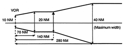
(iv) From a non-directional beacon (NDB), similarly, the corridor width is defined as a borderline starting 5 NM either side of the NDB diverging 7 until a width of 20 NM is reached 40 NM out, thence paralleling the centreline until 80 NM out, thence again diverging 7 until a maximum width of 60 NM is reached 245 NM out. Thereafter, the width remains constant (see Figure 2).
Figure 2
Corridor width from an NDB
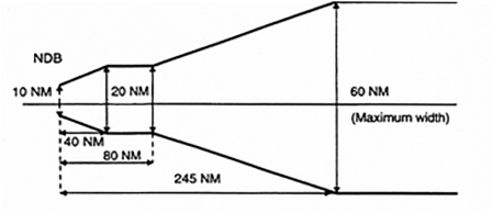
(v) MOCA does not cover any overlapping of the corridor.
(2) Minimum off-route altitude (MORA). MORA is calculated for an area bounded by each or every second LAT/LONG square on the route facility chart (RFC)/terminal approach chart (TAC) and is based on a terrain clearance as follows:
(i) terrain with elevation up to 6 000 ft (2 000 m) – 1 000 ft above the highest terrain and obstructions;
(ii) terrain with elevation above 6 000 ft (2 000 m) – 2 000 ft above the highest terrain and obstructions.
(c) Jeppesen formula (see Figure 3)
(1) MORA is a minimum flight altitude computed by Jeppesen from current operational navigation charts (ONCs) or world aeronautical charts (WACs). Two types of MORAs are charted which are:
(i) route MORAs e.g. 9800a; and
(ii) grid MORAs e.g. 98.
(2) Route MORA values are computed on the basis of an area extending 10 NM to either side of route centreline and including a 10 NM radius beyond the radio fix/reporting point or mileage break defining the route segment.
(3) MORA values clear all terrain and man-made obstacles by 1 000 ft in areas where the highest terrain elevation or obstacles are up to 5 000 ft. A clearance of 2 000 ft is provided above all terrain or obstacles that are 5 001 ft and above.
(4) A grid MORA is an altitude computed by Jeppesen and the values are shown within each grid formed by charted lines of latitude and longitude. Figures are shown in thousands and hundreds of feet (omitting the last two digits so as to avoid chart congestion). Values followed by ± are believed not to exceed the altitudes shown. The same clearance criteria as explained in (c)(3) apply.
Figure 3
Jeppesen formula
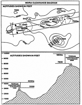
(d) ATLAS formula
(1) Minimum en-route altitude (MEA). Calculation of the MEA is based on the elevation of the highest point along the route segment concerned (extending from navigational aid to navigational aid) within a distance on either side of track as specified in Table 1 below:
Table 1
Minimum safe en-route altitude
|
Segment length |
Distance either side of track |
|
Up to 100 NM |
10 NM * |
|
More than 100 NM |
10 % of segment length up to a maximum of 60 NM ** |
*: This distance may be reduced to 5 NM within terminal control areas (TMAs) where, due to the number and type of available navigational aids, a high degree of navigational accuracy is warranted.
**: In exceptional cases, where this calculation results in an operationally impracticable value, an additional special MEA may be calculated based on a distance of not less than 10 NM either side of track. Such special MEA will be shown together with an indication of the actual width of protected airspace.
(2) The MEA is calculated by adding an increment to the elevation specified above as appropriate, following Table 2 below. The resulting value is adjusted to the nearest 100 ft.
Table 2:
Increment added to the elevation *
|
Elevation of highest point |
Increment |
|
Not above 5 000 ft |
1 500 ft |
|
Above 5 000 ft but not above 10 000 ft |
2 000 ft |
|
Above 10 000 ft |
10 % of elevation plus 1 000 ft |
*: For the last route segment ending over the initial approach fix, a reduction to 1 000 ft is permissible within TMAs where, due to the number and type of available navigation aids, a high degree of navigational accuracy is warranted.
(3) Minimum safe grid altitude (MGA). Calculation of the MGA is based on the elevation of the highest point within the respective grid area.
The MGA is calculated by adding an increment to the elevation specified above as appropriate, following Table 3 below. The resulting value is adjusted to the nearest 100 ft.
Table 3
Minimum safe grid altitude
|
Elevation of highest point |
Increment |
|
Not above 5 000 ft |
1 500 ft |
|
Above 5 000 ft but not above 10 000 ft |
2 000 ft |
|
Above 10 000 ft |
10 % of elevation plus 1 000 ft |
(e) Lido formula
(1) Minimum terrain clearance altitude (MTCA)
The MTCA represents an altitude providing terrain and obstacle clearance for all airways/ATS routes, all standard terminal arrival route (STAR) segments up to IAF or equivalent end point and for selected standard instrument departures (SIDs).
The MTCA is calculated by Lido and covers terrain and obstacle clearance relevant for air navigation with the following buffers:
(i) Horizontal:
(A) for SID and STAR procedures 5 NM either side of centre line; and
(B) for airways/ATS routes 10 NM either side of centre line.
(ii) Vertical:
(A) 1 000 ft up to 6 000 ft; and
(B) 2 000 ft above 6 000 ft.
MTCAs are always shown in feet. The lowest indicated MTCA is 3 100 ft.
(2) Minimum grid altitude (MGA)
MGA represents the lowest safe altitude which can be flown off-track. The MGA is calculated by rounding up the elevation of the highest obstruction within the respective grid area to the next 100 ft and adding an increment of
(i) 1 000 ft for terrain or obstructions up to 6 000 ft; and
(ii) 2 000 ft for terrain or obstructions above 6 000 ft.
MGA is shown in hundreds of feet. The lowest indicated MGA is 2 000 ft. This value is also provided for terrain and obstacles that would result in an MGA below 2 000 ft. An exception is over water areas where the MGA can be omitted.
CAT.OP.MPA.155 Carriage of special categories of passengers (SCPs)
Regulation (EU) No 965/2012
(a) Persons requiring special conditions, assistance and/or devices when carried on a flight shall be considered as SCPs including at least:
(1) persons with reduced mobility (PRMs) who, without prejudice to Regulation (EC) No 1107/2006, are understood to be any person whose mobility is reduced due to any physical disability, sensory or locomotory, permanent or temporary, intellectual disability or impairment, any other cause of disability, or age;
(2) infants and unaccompanied children; and
(3) deportees, inadmissible passengers or prisoners in custody.
(b) SCPs shall be carried under conditions that ensure the safety of the aircraft and its occupants according to procedures established by the operator.
(c) SCPs shall not be allocated, nor occupy, seats that permit direct access to emergency exits or where their presence could:
(1) impede crew members in their duties;
(2) obstruct access to emergency equipment; or
(3) impede the emergency evacuation of the aircraft.
(d) The commander shall be notified in advance when SCPs are to be carried on board.
PROCEDURES
When establishing the procedures for the carriage of SCPs, the operator should take into account the following factors:
(a) the aircraft type and cabin configuration;
(b) the total number of passengers carried on board;
(c) the number and categories of SCPs, which should not exceed the number of passengers capable of assisting them in case of an emergency; and
(d) any other factor(s) or circumstances possibly impacting on the application of emergency procedures by the operating crew members.
PROCEDURES TO PROVIDE INFORMATION TO SCP
The operator procedures on information provided to the SCP should specify the timing and methods on how and when the information can be provided.
CONDITIONS OF SAFE CARRIAGE FOR UNACCOMPANIED CHILDREN
(a) When carrying an unaccompanied child that is not self-reliant, the operator should assess the safety risks to ensure that the child is assisted in case of an emergency situation.
(b) A child under the age of 12 years, separated from the accompanying adult, who is travelling in another cabin class, should be considered as an unaccompanied child in order to ensure that the child is assisted in case of an emergency situation.
PROCEDURES TO PROVIDE INFORMATION TO SCP
Providing information only at the time of booking might not be sufficient to ensure that the SCP is aware of the information at the time of the flight.
INFORMATION PROVIDED TO SCPs
When establishing procedures on the information to be provided to an SCP, the operator should consider informing the SCP that cabin crew can only assist the SCP once the cabin has been evacuated. The following table contains additional information by SCP category:
|
SCP category |
Type of information |
|
Unaccompanied child |
Inform the unaccompanied child on the following: (a) which adult will assist with the operation of the seat belt and the fitting of the oxygen mask if the situation requires it; (b) the content of the passenger safety briefing card; and (c) in case of evacuation, to seek the assistance of adult passenger(s) in contacting a crew member. Inform the passenger sitting next to the unaccompanied child to assist with: (a) providing the child with an oxygen mask in case of decompression after fitting one’s own mask; (b) securing/releasing the child’s seat belt, if necessary; and (c) calling a cabin crew member in all other in-flight situations. When a child and the accompanying adult travel in a different class of cabin, information should be provided to the child and adult that, in the event of an emergency, they should follow the instructions of the cabin crew and not try to reunite inside the cabin as this would slow down the overall evacuation. |
|
Adult travelling with an infant |
Information on brace position for adult with lap-held infant. Information on the use of the loop belt, in case of a lap-held infant. Information to fit own oxygen mask before fitting the infant’s oxygen mask. Information on how to evacuate when carrying an infant: (a) On land, see EASA SIB 2013-06 on evacuation of infants on aircraft equipped with inflatable slides or hatch-type overwing exits; and (b) In case of ditching, how to fit and when to inflate infant flotation aid (e.g. life jacket, flotation device). |
|
Physically disabled passenger (aided walking) |
Inform the SCP to leave mobility aid behind in an emergency evacuation. |
|
Passenger with disability of upper limbs |
Inform the accompanying passenger to: (a) fit the life jacket on the SCP, in case of a ditching evacuation; (b) first put on their own oxygen mask before fitting the SCP’s oxygen mask, in case of decompression; and (c) secure/release the SCP’s seat belt, if necessary. |
|
Passenger with disability of lower limbs |
Inform the SCP: (a) on the location of the nearest suitable exit; and (b) that mobility aids might not be accessible in an emergency evacuation. |
|
Passenger with disability of both upper and lower limbs |
Inform accompanying passenger to secure/release the SCP’s seat belt. Inform the SCP: (a) in case of an evacuation, on the location of the nearest suitable exit; (b) in case of a ditching evacuation, that the accompanying passenger should fit the life jacket on the SCP; and (c) in case of a decompression, that the accompanying passenger should first put on his/her own oxygen mask before fitting the SCP’s oxygen mask. |
|
Visually impaired passenger |
Depending on the level of impairment, inform the visually impaired passenger on the following: (a) seat and seat belt operation; (b) location of the nearest exit (e.g. number of seat rows to the nearest exit); (c) oxygen mask deployment; (d) location of life jacket; (e) brace position; and (f) location of cabin crew call button. If available, take the aircraft demonstration equipment to the passenger for tactile assistance. |
|
Passenger travelling with a recognised assistance dog in the cabin |
Advise how to evacuate guide dog by holding the dog and sliding. |
|
Stretcher occupant |
Inform the stretcher occupant and the accompanying passenger that in case of an evacuation: (a) the stretcher occupant should be evacuated when the cabin area surrounding the stretcher is clear; (b) to evacuate the stretcher occupant without the stretcher, if possible; (c) to be seated when sliding, holding the stretcher occupant in front; and (d) in the event of a ditching evacuation, to fit the life jacket on the stretcher occupant. |
PROCEDURES
A passenger capable of assisting in case of an emergency means a passenger who is not an SCP and has no other role or private responsibility that would prevent him/her from assisting the SCP. For example, an adult travelling alone has no other role or private responsibility, unlike a family travelling together with younger children.
BRIEFING PROCEDURE IN A PLANNED EMERGENCY
In a planned emergency, if time permits, passengers identified by the cabin crew as capable of assisting an SCP should be briefed on the assistance they can provide.
SEATING PROCEDURES
When establishing SCP seating procedures, the operator should take into account the following factors:
(a) If the SCP travels with an accompanying passenger, the accompanying passenger should be seated next to the SCP.
(b) If the SCP is unable to negotiate stairs within the cabin unaided, he/she should not be seated on the upper deck of a multi-deck aircraft if the exits are not certified for emergency evacuation on both land and water.
SEATING ALLOCATION OF SCP WITH A DISABILITY AND/OR RESTRAINT AID
(a) A disability and/or restraint aid that requires to be secured around the back of the seat should not be used if there is a person seated behind unless the seating configuration is approved for the use of such devices. This is to avoid the changed dynamic seat reactions with the disability and/or restraint aid, which may lead to head injury of the passenger seated behind.
(b) If the seat design or installation would prevent head contact of the person seated behind, then no further consideration is necessary.
GROUP SEATING
(a) Taking into account access to exits, groups of non-ambulatory SCPs should be seated throughout the cabin to ensure that each SCP is surrounded by the maximum number of passengers capable of assisting in case of an emergency.
(b) If non-ambulatory SCPs cannot be evenly distributed throughout the cabin, the operator should establish procedures to mitigate the increased safety risk such as seating of passengers capable of assisting in case of an emergency in the vicinity, additional information or training of cabin crew.
(c) A group of passengers whose physical size would possibly prevent them from moving quickly or reaching and passing through an emergency exit, should not occupy the same seat row segment to avoid overloading the structure of the seat.
SEATING ALLOCATION
When establishing the procedure on seating of an SCP, seats should be allocated taking into account the following:
|
SCP category |
Seating allocation procedure |
|
Unaccompanied child |
The seating allocation of an unaccompanied child should allow for visual or audible communication during all phases of the flight with cabin crew. Groups of unaccompanied children should be seated in mix of ages, with the tallest child seated to allow assistance with fitting drop-down oxygen mask to smaller children in case of a decompression. Where possible, one adult should occupy the seat across the aisle next to each row of unaccompanied children. |
|
Passenger travelling with a child of less than 12 years of age |
If a child travels with an accompanying adult in the same class of cabin, the child should be seated in the same seat row segment as the accompanying adult. Where this is not possible, the child should be seated no more than one seat row or aisle away. |
|
Passenger whose physical size would possibly prevent him/her from passing through an emergency exit |
A passenger whose physical size would possibly prevent him/her from passing through an emergency exit (e.g. Type III or Type IV exit), should be seated in the vicinity of a suitable exit, taking into account the size of the exit. Seating of more than one of such passengers in the same seat row segment should be avoided. |
|
Passenger with physical disability of the upper limbs |
A passenger with a physical disability of the upper limbs travelling without an accompanying passenger should be allocated seats during all phases of the flight so that visual and audible communication can be established with the cabin crew. |
|
Passenger with disability of lower limbs |
A passenger with a disability of the lower limbs should be seated in a location providing easy access to floor level exits. |
|
Passenger with disability of both upper and lower limbs |
A passenger with a disability of both upper and lower limbs should be seated in a location providing easy access to floor level exits. |
|
Mentally impaired passenger |
A mentally impaired passenger, who travels without an accompanying passenger, should be allocated seats during all phases of the flight so that visual and audible communication can be established with the cabin crew. |
|
Passenger travelling with recognised assistance dog in the cabin |
Suitable arrangements should be made between the passenger and the operator in advance of a flight where a recognised assistance dog is to be accommodated. A suitable restraint harness should be provided by the owner to secure and restrain the dog during taxi, take-off, landing and turbulence. In cruise, it is acceptable for the dog to be subject to less restraint. |
|
Stretcher occupant |
Where possible, the stretcher should be installed behind a cabin monument. Alternatively, the stretcher could be installed where it can demonstrate compliance with the appropriate certification basis (CS.25.561 and CS.25.562(b), (c)(7), (8)). Stretcher installation should be as close to the floor level non-overwing exits as practical; preferably close to a required cabin crew station with an adjacent seat for the designated accompanying passenger. |
CAT.OP.MPA.160 Stowage of baggage and cargo
Regulation (EU) No 965/2012
The operator shall establish procedures to ensure that:
(a) only hand baggage that can be adequately and securely stowed is taken into the passenger compartment; and
(b) all baggage and cargo on board that might cause injury or damage, or obstruct aisles and exits if displaced, is stowed so as to prevent movement.
STOWAGE PROCEDURES
Procedures established by the operator to ensure that hand baggage and cargo are adequately and securely stowed should take account of the following:
(a) each item carried in a cabin should be stowed only in a location that is capable of restraining it;
(b) weight limitations placarded on or adjacent to stowages should not be exceeded;
(c) under seat stowages should not be used unless the seat is equipped with a restraint bar and the baggage is of such size that it may adequately be restrained by this equipment;
(d) items should not be stowed in lavatories or against bulkheads that are incapable of restraining articles against movement forwards, sideways or upwards and unless the bulkheads carry a placard specifying the greatest mass that may be placed there;
(e) baggage and cargo placed in lockers should not be of such size that they prevent latched doors from being closed securely;
(f) baggage and cargo should not be placed where it can impede access to emergency equipment; and
(g) checks should be made before take-off, before landing and whenever the ‘fasten seat belts’ signs are illuminated or it is otherwise so ordered to ensure that baggage is stowed where it cannot impede evacuation from the aircraft or cause injury by falling (or other movement), as may be appropriate to the phase of flight.
CARRIAGE OF CARGO IN THE PASSENGER COMPARTMENT
The following should be observed before carrying cargo in the passenger compartment:
(a) for aeroplanes:
(1) dangerous goods should not be allowed; and
(2) a mix of passengers and live animals should only be allowed for pets weighing not more than 8 kg and guide dogs;
(b) for aeroplanes and helicopters:
(1) the mass of cargo should not exceed the structural loading limits of the floor or seats;
(2) the number/type of restraint devices and their attachment points should be capable of restraining the cargo in accordance with applicable Certification Specifications; and
(3) the location of the cargo should be such that, in the event of an emergency evacuation, it will not hinder egress nor impair the crew’s view.
CAT.OP.MPA.165 Passenger seating
Regulation (EU) No 965/2012
The operator shall establish procedures to ensure that passengers are seated where, in the event that an emergency evacuation is required, they are able to assist and not hinder evacuation of the aircraft.
EMERGENCY EXIT SEATING
The operator should make provisions so that:
(a) a passenger occupies a seat at least on each side in a seat row with direct access to an emergency exit (not staffed by a cabin crew member) during taxiing, take-off and landing unless this would be impracticable due to a low number of passengers or might negatively impact the mass and balance limitations.
(b) those passengers who are allocated seats that permit direct access to emergency exits appear to be reasonably fit, strong, and be able and willing to assist the rapid evacuation of the aircraft in an emergency after an appropriate briefing by the crew;
(c) in all cases, passengers who, because of their condition, might hinder other passengers during an evacuation or who might impede the crew in carrying out their duties, should not be allocated seats that permit direct access to emergency exits. If procedures cannot be reasonably implemented at the time of passenger ‘check-in’, the operator should establish an alternative procedure which ensures that the correct seat allocations will, in due course, be made.
ACCESS TO EMERGENCY EXITS
The following categories of passengers are among those who should not be allocated to, or directed to, seats that permit direct access to emergency exits:
(a) passengers suffering from obvious physical or mental disability to the extent that they would have difficulty in moving quickly if asked to do so;
(b) passengers who are either substantially blind or substantially deaf to the extent that they might not readily assimilate printed or verbal instructions given;
(c) passengers who because of age or sickness are so frail that they have difficulty in moving quickly;
(d) passengers who are so obese that they would have difficulty in moving quickly or reaching and passing through the adjacent emergency exit;
(e) children (whether accompanied or not) and infants;
(f) deportees, inadmissible passengers or persons in custody; and
(g) passengers with animals.
DIRECT ACCESS
‘Direct access’ means a seat from which a passenger can proceed directly to the exit without entering an aisle or passing around an obstruction.
EMERGENCY EXIT SEATING
When allocating a seat in a seat row with direct access to an emergency exit, the operator should consider at least the following:
(a) providing the passenger with the applicable emergency exit seating restrictions prior to boarding, or upon assigning a passenger to a seat, e.g. at the stage of booking, or check-in, or at the airport;
(b) utilising, as far as practicable, cabin crew members that are additional to the minimum required cabin crew complement, or positioning crew members, if available on board.
CAT.OP.MPA.170 Passenger briefing
Regulation (EU) 2019/1384
The operator shall ensure that passengers are:
(a) given briefings and demonstrations relating to safety in a form that facilitates the application of the procedures applicable in the event of an emergency; and
(b) provided with a safety briefing card on which picture-type instructions indicate the operation of safety and emergency equipment and emergency exits likely to be used by passengers.
PASSENGER BRIEFING
Passenger briefings should contain the following:
(a) Before take-off
(1) Passengers should be briefed on the following items, if applicable:
(i) any cabin secured aspects, e.g. required position of seatbacks, tray tables, footrests, window blinds, etc. as applicable;
(ii) emergency lighting (floor proximity escape path markings, exit signs);
(iii) correct stowage of hand baggage and the importance of leaving hand baggage behind in case of evacuation;
(iv) the use and stowage of portable electronic devices, including in-flight entertainment (IFE) systems;
(v) the location and presentation of the safety briefing card, the importance of its contents and the need for passengers to review it prior to take-off; and
(vi) compliance with ordinance signs, pictograms or placards, and crew member instructions; and
(2) Passengers should receive a demonstration of the following:
(i) the use of safety belts or restraint systems, including how to fasten and unfasten the safety belts or restraint systems;
(ii) the location of emergency exits;
(iii) the location and use of oxygen equipment, if required. Passengers should also be briefed to extinguish all smoking materials when oxygen is being used; and
(iv) the location and use of life-jackets if required.
(3) Passengers occupying seats with direct access to emergency exits not staffed by cabin crew members should receive an additional briefing on the operation and use of the exit.
(b) After take-off
(1) Passengers should be reminded of the following, if applicable:
(i) use of safety belts or restraint systems including the safety benefits of having safety belts fastened when seated irrespective of seat belt sign illumination; and
(ii) caution when opening overhead compartments.
(c) Before landing
(1) Passengers should be reminded of the following, if applicable:
(i) use of safety belts or restraint systems;
(ii) any cabin secured aspects, e.g. required position of seatbacks, tray tables, footrests, window blinds, etc. as applicable;
(iii) correct stowage of hand baggage and the importance of leaving hand baggage behind in case of evacuation;
(iv) the use and stowage of portable electronic devices; and
(v) the location of the safety briefing card, the importance of its contents and its review.
(d) After landing
(1) Passengers should be reminded of the following:
(i) use of safety belts or restraint systems;
(ii) the use and stowage of portable electronic devices; and
(iii) caution when opening overhead compartments.
(1) Passengers should be instructed as appropriate to the circumstances.
(f) Smoking regulations
(1) The operator should determine the frequency of briefings or reminding passengers about the smoking regulations.
PASSENGER BRIEFING
(a) The operator may replace the briefing/demonstration as set out in AMC1 CAT.OP.MPA.170 with a passenger training programme covering all safety and emergency procedures for a given type of aircraft.
(b) Only passengers who have been trained according to this programme and have flown on the aircraft type within the last 90 days may be carried on board without receiving a briefing/demonstration.
SINGLE-PILOT OPERATIONS WITHOUT CABIN CREW
For single-pilot operations without cabin crew, the commander should provide safety briefings to passengers except during critical phases of flight and taxiing.
AMC3 CAT.OP.MPA.170 Passenger briefing
ED Decision 2019/019/R
IN-FLIGHT ENTERTAINMENT (IFE) SYSTEMS
When IFE systems are available by means of equipment that can be handled by passengers, including portable electronic devices (PEDs), provided by the operator for the purpose of IFE, appropriate information containing at least the following should be made available to passengers:
(a) instructions on how to safely operate the IFE system for personal use in normal conditions;
(b) restrictions, including stowage of retractable or loose items of equipment (e.g. screens or remote controls) during taxiing, take-off and landing, and in abnormal or emergency conditions; and
(c) the instruction to alert cabin crew members in case of IFE system malfunction in accordance with point (f)(9) of GM2 CAT.OP.MPA.170.
BRIEFING OF PASSENGERS OCCUPYING SEATS WITH DIRECT ACCESS TO EMERGENCY EXITS NOT STAFFED BY CABIN CREW MEMBERS
(a) The emergency exit briefing should contain instructions on the operation of the exit, assessment of surrounding conditions for the safe use of the exit, and recognition of emergency commands given by the crew.
(b) Cabin crew should verify that the passenger(s) is (are) able and willing to assist the crew in case of an emergency and that the passenger(s) has (have) understood the instructions.
SAFETY BRIEFING MATERIAL
(a) Safety briefing material may include but is not limited to an audio-visual presentation, such as a safety video or a safety briefing card. Information in the safety briefing material should be relevant to the aircraft type and the installed equipment and should be consistent with the operator’s procedures. Information in the safety briefing material should be presented in a clear and unambiguous manner and in a form easily understandable to passengers.
(b) For those passengers occupying seats with direct access to emergency exits, the operator should consider providing a separate briefing card, which contains a summary of the exit briefing information.
(c) The safety briefing card should be designed, and the information should be provided, in a size easily visible to the passenger. The safety briefing card should be stowed in a location from where it is easily visible and reachable to the seated passenger and from where it cannot easily fall out. Information should be presented in a pictographic form and should be consistent with the placards used in the aircraft. Written information should be kept to the necessary minimum. The safety briefing card should only contain information relevant to safety.
(d) The operator conducting an operation with no cabin crew should consider including expanded information, such as location and use of fire extinguisher, oxygen system if different from the drop-down system, etc.
(e) The safety video should be structured in a pace that allows a continuous ability to follow the information presented. The operator may consider including sign language or subtitles to simultaneously complement the soundtrack.
(f) The operator should consider including the following information in its safety briefing material:
(1) hand baggage:
(i) correct versus forbidden stowage locations (e.g. exits, aisles, etc.);
(2) safety belts and other restraint systems:
(i) when and how to use safety belts and other restraint systems;
(ii) restraint of infants and children;
(iii) additional installed systems, e.g. airbag;
(3) drop-down oxygen system:
(i) location;
(ii) activation;
(iii) indication of active oxygen supply;
(iv) correct and timely donning of oxygen mask;
(v) assisting others;
(4) flotation devices:
(i) stowage locations (including if different in various cabin sections);
(ii) use for adult, child and infant;
(iii) features, e.g. straps, toggles, tubes, signalling light, whistle;
(iv) when and where to inflate a life jacket;
(v) flotation devices for infants;
(5) emergency exits:
(i) number and location;
(ii) method of operation, including alternative operation in case of ditching;
(iii) surrounding conditions prior to opening (e.g. fire, smoke, water level, etc.);
(iv) unusable exit;
(v) alternative egress routes in case of unusable exit(s);
(vi) leaving hand baggage behind;
(vii) method of egress through exit including with infants and children;
(viii) awareness of exit height;
(ix) awareness of propellers;
(6) escape routes: depiction of routes:
(i) to the exits (inside the aircraft);
(ii) movement on a double-deck aircraft;
(iii) via the wing to the ground;
(iv) on the ground away from the aircraft;
(7) assisting evacuation means:
(i) location of available equipment (e.g. life raft, installed slide/raft, etc.);
(ii) awareness of the evacuation equipment’s features;
(iii) operation of the available equipment (activation, detachment, etc.);
(iv) method of boarding the device including with infants and children;
(v) use of shoes;
(vi) method of evacuation through exits with no assisting evacuation means;
(8) brace position:
(i) appropriate method to the applicable facing direction;
(ii) alternative brace positions for e.g. expectant mothers, passengers with lap-held infants, tall or large individuals, children, etc.;
(9) portable electronic devices, including spare batteries:
(i) allowed versus forbidden devices;
(ii) use in various flight phases including during safety briefing;
(iii) stowage;
(iv) danger of fire in case the device is damaged;
(v) the need to call for immediate assistance in case a device is damaged, hot, produces smoke, is lost, or falls into the seat structure (including advice to refrain from manipulating the seat);
(vi) the need to monitor devices during charging;
(10) cabin secured aspects:
(i) required position of seatbacks, headrests, tray tables, footrests, window blinds, in-seat video screens and their control gadgets, etc.;
(ii) caution when opening overhead compartments;
(11) smoking regulations (e.g. phase of flight, electronic smoking devices, pipes, etc.) including smoking in the lavatory;
(12) floor proximity escape path marking:
(i) location;
(ii) purpose in case of darkness or smoke;
(13) actions in case of an emergency (e.g. remove sharp objects, fasten seat belt, open window blind, etc.);
(14) any other safety aspects.
CAT.OP.MPA.175 Flight preparation
Regulation (EU) 2021/1296
(a) An operational flight plan shall be completed for each intended flight based on considerations of aircraft performance, other operating limitations and relevant expected conditions on the route to be followed and at the aerodromes/operating sites concerned.
(b) The flight shall not be commenced unless the commander is satisfied that:
(1) all items stipulated in 2.a.3 of Annex IV to Regulation (EC) No 216/2008 concerning the airworthiness and registration of the aircraft, instrument and equipment, mass and centre of gravity (CG) location, baggage and cargo and aircraft operating limitations can be complied with;
(2) the aircraft is not operated contrary to the provisions of the configuration deviation list (CDL);
(3) the parts of the operations manual that are required for the conduct of the flight are available;
(4) the documents, additional information and forms required to be available by CAT.GEN.MPA.180 are on board;
(5) current maps, charts and associated documentation or equivalent data are available to cover the intended operation of the aircraft including any diversion that may reasonably be expected;
(6) space-based facilities, ground facilities and services that are required for the planned flight are available and adequate;
(7) the provisions specified in the operations manual in respect of fuel/energy, oil, oxygen, minimum safe altitudes, aerodrome operating minima and availability of alternate aerodromes, where required, can be complied with for the planned flight;
(7a) any navigational database required for performance-based navigation is suitable and current; and
(8) any additional operational limitation can be complied with.
(c) Notwithstanding (a), an operational flight plan is not required for operations under VFR of:
(1) other-than complex motor-powered aeroplane taking off and landing at the same aerodrome or operating site; or
(2) helicopters with an MCTOM of 3 175 kg or less, by day and over routes navigated by reference to visual landmarks in a local area as specified in the operations manual.
FLIGHT PREPARATION FOR PBN OPERATIONS
(a) The flight crew should ensure that RNAV 1, RNAV 2, RNP 1 RNP 2, and RNP APCH routes or procedures to be used for the intended flight, including for any alternate aerodromes, are selectable from the navigation database and are not prohibited by NOTAM.
(b) The flight crew should take account of any NOTAMs or operator briefing material that could adversely affect the aircraft system operation along its flight plan including any alternate aerodromes.
(c) When PBN relies on GNSS systems for which RAIM is required for integrity, its availability should be verified during the preflight planning. In the event of a predicted continuous loss of fault detection of more than five minutes, the flight planning should be revised to reflect the lack of full PBN capability for that period.
(d) For RNP 4 operations with only GNSS sensors, a fault detection and exclusion (FDE) check should be performed. The maximum allowable time for which FDE capability is projected to be unavailable on any one event is 25 minutes. If predictions indicate that the maximum allowable FDE outage will be exceeded, the operation should be rescheduled to a time when FDE is available.
(e) For RNAV 10 operations, the flight crew should take account of the RNAV 10 time limit declared for the inertial system, if applicable, considering also the effect of weather conditions that could affect flight duration in RNAV 10 airspace. Where an extension to the time limit is permitted, the flight crew will need to ensure that en route radio facilities are serviceable before departure, and to apply radio updates in accordance with any AFM limitation.
DATABASE SUITABILITY
(a) The flight crew should check that any navigational database required for PBN operations includes the routes and procedures required for the flight.
(b) The database validity (current AIRAC cycle) should be checked before the flight.
(c) Navigation databases should be current for the duration of the flight. If the AIRAC cycle is due to change during flight, the flight crew should follow procedures established by the operator to ensure the accuracy of navigation data, including the suitability of navigation facilities used to define the routes and procedures for the flight.
(d) An expired database may only be used if the following conditions are satisfied:
(1) the operator has confirmed that the parts of the database which are intended to be used during the flight and any contingencies that are reasonable to expect are not changed in the current version;
(2) any NOTAMs associated with the navigational data are taken into account;
(3) maps and charts corresponding to those parts of the flight are current and have not been amended since the last cycle;
(4) any MEL limitations are observed; and
(5) the database has expired by no more than 28 days.
OPERATIONAL FLIGHT PLAN — COMPLEX MOTOR-POWERED AIRCRAFT
(a) The operational flight plan used and the entries made during flight should contain the following items:
(1) aircraft registration;
(2) aircraft type and variant;
(3) date of flight;
(4) flight identification;
(5) names of flight crew members;
(6) duty assignment of flight crew members;
(7) place of departure;
(8) time of departure (actual off-block time, take-off time);
(9) place of arrival (planned and actual);
(10) time of arrival (actual landing and on-block time);
(11) type of operation (ETOPS, VFR, ferry flight, etc.);
(12) route and route segments with checkpoints/waypoints, distances, time and tracks;
(13) planned cruising speed and flying times between check-points/waypoints (estimated, revised, and actual times overhead);
(14) safe altitudes and minimum levels;
(15) planned altitudes and flight levels;
(16) fuel calculations (records of in-flight fuel checks);
(17) fuel on board when starting engines;
(18) alternate(s) for destination, including the information required in (a)(12) to (15), as well as destination 2 and destination 2 alternate aerodromes in case of a reduced contingency fuel (RCF) procedure;
(19) where applicable, a take-off alternate and fuel ERA aerodrome(s);
(20) initial ATS flight plan clearance and subsequent reclearance;
(21) in-flight replanning calculations; and
(22) meteorological information, as specified in point (a) of point MET.TR.215 of Part-MET.
(b) Items that are readily available in other documentation or from another acceptable source or are irrelevant to the type of operation may be omitted from the operational flight plan.
(c) The operational flight plan and its use should be described in the operations manual.
(d) All entries on the operational flight plan should be made concurrently and be permanent in nature.
OPERATIONAL FLIGHT PLAN — OTHER-THAN-COMPLEX MOTOR-POWERED AIRCRAFT OPERATIONS AND LOCAL OPERATIONS
(e) An operational flight plan may be established in a simplified form relevant to the type of operation for operations with other-than-complex motor-powered aircraft as well as local operations with any aircraft. Local operations should be defined in the OM.
(f) No entries should be made in the operational flight plan during the flight.
OPERATIONAL FLIGHT PLAN PRODUCED BY A COMPUTERISED FLIGHT-PLANNING SYSTEM
(g) When the operator uses a computerised flight-planning system to produce an operational flight plan, the functionality of this system should be described in the OM.
(h) If the computerised flight-planning system is used in conjunction with a basic fuel scheme with variations or an individual fuel scheme, the operator should ensure that the quality and the proper functionality of the software are tested after each upgrade. The test should verify that the changes to the software do not affect the final output.
CONVERSION TABLES
The documentation should include any conversion tables necessary to support operations where metric heights, altitudes and flight levels are used.
CAT.OP.MPA.177 Submission of the ATS flight plan
Regulation (EU) 2021/1296
(a) If an air traffic services (ATS) flight plan is not submitted because it is not required by the rules of the air, adequate information shall be deposited in order to permit alerting services to be activated if required.
(b) When operating from a site where it is impossible to submit an ATS flight plan, the ATS flight plan shall be transmitted as soon as possible after take-off by the commander or the operator.
AMC1 CAT.OP.MPA.177 Submission of the ATS flight plan
ED Decision 2022/005/R
FLIGHTS WITHOUT AN ATS FLIGHT PLAN
(a) When unable to submit or close the ATS flight plan due to lack of ATS facilities or of any other means of communications to ATS, the operator should establish procedures, instructions, and a list of nominated persons to be responsible for alerting search and rescue (SAR) services.
(b) To ensure that each flight is located at all times, these instructions should:
(1) provide the nominated person with at least the information required to be included in a VFR flight plan, and the location, date, and estimated time for re-establishing communications;
(2) if an aircraft is overdue or missing, ensure that the appropriate ATS or SAR service is notified; and
(3) ensure that the information will be retained at a designated place until the completion of the flight.
CAT.OP.MPA.180 Fuel/energy scheme – aeroplanes
Regulation (EU) 2021/1296
(a) The operator shall establish, implement, and maintain a fuel/energy scheme that:
(1) is appropriate for the type(s) of operation performed;
(2) corresponds to the capability of the operator to support its implementation; and
(3) is either:
(i) a basic fuel/energy scheme, which shall form the basis for a basic fuel/energy scheme with variations and an individual fuel/energy scheme; the basic fuel/energy scheme derives from a large-scale analysis of safety and operational data from previous performance and experience of the industry, applying scientific principles; the basic fuel/energy scheme shall ensure, in this order, a safe, effective, and efficient operation of the aircraft; or
(ii) a basic fuel/energy scheme with variations, which is a basic fuel/energy scheme where the analysis referred to in point (i) is used to establish a variation to the basic fuel/energy scheme that ensures, in this order, a safe, effective, and efficient operation of the aircraft; or
(iii) an individual fuel/energy scheme, which derives from a comparative analysis of the operator’s safety and operational data, applying scientific principles; the analysis is used to establish a fuel/energy scheme with a higher or equivalent level of safety to that of the basic fuel/energy scheme that ensures, in this order, a safe, effective, and efficient operation of the aircraft.
(b) All fuel/energy schemes shall comprise:
(1) a fuel/energy planning and in-flight re-planning policy;
(2) an aerodrome selection policy; and
(3) an in-flight fuel/energy management policy.
(c) The fuel/energy scheme and any change to it shall require prior approval by the competent authority.
(d) When the operator intends to apply for an individual fuel/energy scheme, it shall:
(1) establish a baseline safety performance of its current fuel/energy scheme;
(2) demonstrate its capability to support the implementation of the proposed individual fuel/energy scheme, including the capability to exercise adequate operational control and to ensure exchange of the relevant safety information between the operational control personnel and the flight crew; and
(3) make a safety risk assessment that demonstrates how an equivalent level of safety to that of the current fuel/energy scheme is achieved.
AMC1 CAT.OP.MPA.180 Fuel/energy scheme — aeroplanes
ED Decision 2022/005/R
INDIVIDUAL FUEL SCHEME
(a) Prior to submitting an individual fuel scheme for approval, the operator should perform all the following actions to establish a baseline safety performance:
(1) measure the baseline safety performance of its operation with the current fuel scheme by:
(i) selecting safety performance indicators (SPIs) and targets that are agreed with the competent authority; and
(ii) collecting statistically relevant data for a period of at least 2 years of continuous operation (note: the number of flights should be sufficient to provide data to support the intended deviation);
(2) identify the hazards associated with the individual fuel scheme and carry out a safety risk assessment of these hazards; and
(3) based on this safety risk assessment, establish a mechanism for risk monitoring and risk control to ensure an equivalent level of safety to that of the current fuel scheme.
(b) In order to ensure the approval of the competent authority and its continuous oversight, the operator should establish an effective continuous reporting system to the competent authority on the safety performance and regulatory compliance of the individual fuel scheme.
(c) When determining the extent of the deviation from the current fuel scheme, the operator should take into account at least the following elements for the relevant area of operation:
(1) the available aerodrome technologies, capabilities, and infrastructure;
(2) the reliability of meteorological and aerodrome information;
(3) the reliability of the aeroplane systems, especially the time-limited ones; and
(4) the type of ATS provided and, where applicable, characteristics and procedures of the air traffic flow management and of the airspace management.
(d) An operator wishing to apply for the approval of an individual fuel scheme should be able to demonstrate that it exercises sufficient organisational control over internal processes and the use of resources. The operator should adapt its management system to ensure that:
(1) processes and procedures are established to support the individual fuel scheme;
(2) involved flight crew and personnel are trained and competent to perform their tasks; and
(3) the implementation and effectiveness of such processes, procedures, and training are monitored.
(e) The operator should have as a minimum the following operational capabilities that support the implementation of an individual fuel scheme:
(1) use a suitable computerised flight-planning system;
(2) ensure that the planning of flights is based upon current aircraft-specific data that is derived from a fuel consumption monitoring system and reliable meteorological data;
(3) have airborne fuel prediction systems;
(4) be able to operate in required navigation performance (RNP) 4 oceanic and remote continental airspace and in area navigation (RNAV) 1 continental en-route airspace, as applicable;
(5) be able to perform APCHs that require an LVO approval and RNP APCHs down to VNAV minima; and
(6) update the available landing options by establishing an operational control system with the following capabilities:
(i) flight monitoring or flight watch;
(ii) collection and continuous monitoring of reliable meteorological, aerodrome, and traffic information;
(iii) two independent airborne communications systems to achieve rapid and reliable exchange of relevant safety information between flight operations personnel and flight crew during the entire flight; and
(iv) monitoring of the status of aircraft systems that affect fuel consumption and of ground and aircraft systems that affect landing capabilities.
(f) After receiving the approval, the operator should:
(1) continually measure and monitor the outcome of each SPI; and
(2) in case of degradation of any SPI:
(i) assess the root cause of the degradation;
(ii) identify remedial actions to restore the baseline safety performance; and
(iii) when the associated safety performance target is not met, inform the authority as soon as practicable.
GM1 CAT.OP.MPA.180 Fuel/energy scheme — aeroplanes
ED Decision 2022/005/R
FUEL SCHEMES
An operator can choose between three different fuel schemes. For the development of each fuel scheme, the following AMC are applicable:
(a) Basic fuel scheme: all the AMC that apply to the basic fuel scheme.
(b) Basic fuel scheme with variations: when an operator decides to deviate fully or partly from the basic fuel schemes, the AMC for basic fuel schemes with variations apply to the specific deviation.
(c) Individual fuel scheme: when an operator wishes to apply an individual fuel scheme, the AMC for the individual fuel scheme apply; for the part of the scheme where the operator still follows the basic fuel scheme, the operator should apply the AMC referred to in (a) and (b).
GM2 CAT.OP.MPA.180 Fuel/energy scheme — aeroplanes
ED Decision 2022/005/R
INDIVIDUAL FUEL SCHEMES — BASELINE SAFETY PERFORMANCE INDICATORS (SPIs) AND EQUIVALENT LEVEL OF SAFETY
(a) Establishing the baseline safety performance of a current fuel scheme involves collecting historical statistical data for the selected SPIs over a defined period of time, e.g. a minimum of 2 years. The safety performance of the operator’s processes is then measured against this baseline safety performance before and after implementation of the individual fuel scheme.
(b) Agreed SPIs should be commensurate with the complexity of the operational context, the extent of the deviations of the individual fuel scheme from the current fuel scheme, and the availability of resources to address those SPIs.
(c) The following is a non-exhaustive list of SPIs that are used to measure the baseline safety performance:
(1) flights with 100 % consumption of the contingency fuel;
(2) flights with a percentage consumption of the contingency fuel (e.g. 85 %), as agreed by the operator and the competent authority;
(3) difference between planned and actual trip fuel;
(4) landings with less than the final reserve fuel (FRF) remaining;
(5) flights landing with less than minutes of fuel remaining (e.g. 45 minutes), as agreed by the operator and the competent authority;
(6) ‘MINIMUM FUEL’ declarations;
(7) ‘MAYDAY MAYDAY MAYDAY FUEL’ declarations;
(8) in-flight re-planning to the planned destination due to fuel shortage, including committing to land at the destination by cancelling the planned destination alternate;
(9) diversion to an en route alternate (ERA) aerodrome to protect the FRF;
(10) diversion to the destination alternate aerodrome; and
(11) any other indicator with the potential of demonstrating the suitability or unsuitability of the alternate aerodrome and fuel planning policy.
Note: Although the above-list includes quantitative SPIs, for certain non-data-based monitoring SPIs, alert and target levels may be qualitative in nature.
(d) Equivalent level of safety: SPIs and associated targets that are achieved after the introduction of an individual fuel scheme ‘should be equivalent to’ or ‘exceed’ the SPIs and associated targets that were used in the previously approved fuel scheme. To determine if such equivalence is achieved, the operator should carefully compare with one another the safety performance of operational activities before and after the application of the individual fuel scheme. For example, the operator should ensure that the average number of landings with less than the FRF does not increase after the introduction of the individual fuel scheme.
(e) The applicability of the individual fuel scheme may be limited to a specific aircraft fleet or type/variant of aircraft or area of operations. Different policies may be established as long as the procedures clearly specify the boundaries of each policy so that the flight crew is aware of the policy being applied: for example, the operator may wish to deviate from the basic 5 % contingency fuel policy only in certain areas of operations or only for a specific aircraft fleet or type/variant of aircraft. The safety performance of the fuel scheme may be measured according to the relevant area of operation or aircraft fleet or type/variant of aircraft so that any degradation of the safety performance can be isolated and mitigated separately. In that case, the approval for a deviation may be suspended for the affected area of operations and/or type/variant of aircraft until the required safety performance is achieved.
Note: ICAO Doc 9976 Flight Planning and Fuel Management (FPFM) Manual (1st Edition, 2015) and the EASA Fuel Manual provide further guidance.
GM3 CAT.OP.MPA.180 Fuel/energy scheme — aeroplanes
ED Decision 2022/005/R
INDIVIDUAL FUEL SCHEMES — OPERATOR CAPABILITIES — COMMUNICATIONS SYSTEMS
(a) In the context of point (e)(6) of AMC1 CAT.OP.MPA.180, the availability of two independent communications systems at dispatch is particularly relevant for flights over oceanic and remote areas (e.g. when flying over the ocean without VHF coverage, operators need either HF or satellite communications (SATCOM)).
(b) Consideration should also be given to the operational control system associated with the use of the aircraft communications addressing and reporting system (ACARS). Two communications systems (e.g. VHF and SATCOM) should be used to support the ACARS functionality to ensure the required degree of independence unless the operator has established contingency procedures for reverting to voice communication only.
(c) Additional means of communications may be required by other regulations that are not linked to fuel schemes.
Note: For further information, see ICAO Doc 9976 Flight Planning and Fuel Management (FPFM) Manual, Appendix 7 to Chapter 5 A performance-based approach job-aid for an approving authority (1st Edition, 2015).
CAT.OP.MPA.181 Fuel/energy scheme – fuel/energy planning and in-flight re-planning policy – aeroplanes
Regulation (EU) 2021/1296
(a) The operator shall:
(1) establish a fuel/energy planning and in-flight re-planning policy as part of the fuel/energy scheme;
(2) ensure that the aeroplane carries a sufficient amount of usable fuel/energy to safely complete the planned flight and to allow for deviations from the planned operation;
(3) develop procedures for the fuel/energy planning and in-flight re-planning policy that shall be contained in the operations manual.
(4) ensure that the fuel/energy planning of the flight is based on:
(i) current aircraft-specific data derived from a fuel/energy consumption monitoring system or, if not available;
(ii) data provided by the aeroplane manufacturer.
(b) The operator shall ensure that the planning of flights includes the operating conditions under which the flight is to be conducted; the operating conditions shall include at least:
(1) aircraft fuel/energy consumption data;
(2) anticipated masses;
(3) anticipated meteorological conditions;
(4) the effects of deferred maintenance items and/or of configuration deviations;
(5) the expected departure and arrival routing and runways; and
(6) anticipated delays.
(c) The operator shall ensure that the pre-flight calculation of the usable fuel/energy that is required for a flight includes:
(1) taxi fuel/energy that shall not be less than the amount expected to be used prior to take‑off;
(2) trip fuel/energy that shall be the amount of fuel/energy that is required to enable the aeroplane to fly from take-off, or from the point of in-flight re-planning, to landing at the destination aerodrome;
(3) contingency fuel/energy that shall be the amount of fuel/energy required to compensate for unforeseen factors;
(4) destination alternate fuel/energy:
(i) when a flight is operated with at least one destination alternate aerodrome, it shall be the amount of fuel/energy required to fly from the destination aerodrome to the destination alternate aerodrome; or
(ii) when a flight is operated with no destination alternate aerodrome, it shall be the amount of fuel/energy required to hold at the destination aerodrome, while enabling the aeroplane to perform a safe landing, and to allow for deviations from the planned operation; as a minimum, this amount shall be 15-minute fuel/energy at holding speed at 1 500ft (450 m) above the aerodrome elevation in standard conditions, calculated according to the estimated aeroplane mass on arrival at the destination aerodrome;
(5) final reserve fuel/energy that shall be the amount of fuel/energy that is calculated at holding speed at 1 500ft (450 m) above the aerodrome elevation in standard conditions according to the aeroplane estimated mass on arrival at the destination alternate aerodrome, or destination aerodrome when no destination alternate aerodrome is required, and shall not be less than:
(i) for aeroplanes with reciprocating engines, the fuel/energy to fly for 45 minutes; or
(ii) for turbine-engined aeroplanes, the fuel/energy to fly for 30 minutes;
(6) additional fuel/energy, if required by the type of operation; it shall be the amount of fuel/energy to enable the aeroplane to land at a fuel/energy en route alternate aerodrome (fuel/energy ERA aerodrome critical scenario) in the event of an aircraft failure that significantly increases the fuel/energy consumption at the most critical point along the route; this additional fuel/energy is required only if the minimum amount of fuel/energy that is calculated according to points (c)(2) to (c)(5) is not sufficient for such an event;
(7) extra fuel/energy to take into account anticipated delays or specific operational constraints; and
(8) discretionary fuel/energy, if required by the commander.
(d) The operator shall ensure that in-flight re-planning procedures for calculating the usable fuel/energy that is required when a flight proceeds along a route or to a destination aerodrome other than the ones originally planned include points (c)(2) to (c)(7).
AMC1 CAT.OP.MPA.181 Fuel/energy scheme — fuel/energy planning and in-flight re-planning policy — aeroplanes
ED Decision 2022/005/R
BASIC FUEL SCHEME — PRE-FLIGHT CALCULATION OF USABLE FUEL FOR PERFORMANCE CLASS A AEROPLANES
For the pre-flight calculation of the usable fuel in accordance with point CAT.OP.MPA.181, the operator should:
(a) for taxi fuel, take into account the local conditions at the departure aerodrome and the APU consumption;
(b) for trip fuel, include:
(1) fuel for take-off and climb from the aerodrome elevation to the initial cruising level/altitude, taking into account the expected departure routing;
(2) fuel from the top of climb to the top of descent, including any step climb/descent;
(3) fuel from the top of descent to the point where the approach procedure is initiated, taking into account the expected arrival routing; and
(4) fuel for making an approach and landing at the destination aerodrome;
(c) for contingency fuel, calculate for unforeseen factors either:
(1) 5 % of the planned trip fuel or, in the event of in-flight re-planning, 5 % of the trip fuel for the remainder of the flight; or
(2) an amount to fly for 5 minutes at holding speed at 1 500 ft (450 m) above the destination aerodrome in standard conditions,
whichever is the higher;
(d) for destination alternate fuel, include:
(1) when the aircraft is operated with one destination alternate aerodrome:
(i) fuel for a missed approach from the applicable DA/H or MDA/H at the destination aerodrome to the missed-approach altitude, taking into account the complete missed-approach procedure;
(ii) fuel for climb from the missed-approach altitude to the cruising level/altitude, taking into account the expected departure routing;
(iii) fuel for cruising from the top of climb to the top of descent, taking into account the expected routing;
(iv) fuel for descent from the top of descent to the point where the approach is initiated, taking into account the expected arrival routing; and
(v) fuel for making an approach and landing at the destination alternate aerodrome; and
(2) when the aircraft is operated with two destination alternate aerodromes, the amount of fuel that is calculated in accordance with point (d)(1), based on the destination alternate aerodrome that requires the greater amount of fuel;
(e) for FRF, comply with point CAT.OP.MPA.181(c);
(f) for additional fuel, include an amount of fuel that allows the aeroplane to proceed, in the event of an engine failure or loss of pressurisation, from the most critical point along the route to a fuel en route alternate (fuel ERA) aerodrome in the relevant aircraft configuration, hold there for 15 minutes at 1 500 ft (450 m) above the aerodrome elevation in standard conditions, make an approach, and land;
(g) for extra fuel, include anticipated delays or specific operational constraints that can be predicted; and
(h) for discretionary fuel, include a quantity at the sole discretion of the commander.
AMC2 CAT.OP.MPA.181 Fuel/energy scheme — fuel/energy planning and in-flight re-planning policy — aeroplanes
ED Decision 2022/005/R
BASIC FUEL SCHEME — PRE-FLIGHT CALCULATION OF USABLE FUEL FOR PERFORMANCE CLASS B and C AEROPLANES
The pre-flight calculation of required usable fuel should include:
(a) taxi fuel, if significant;
(b) trip fuel;
(c) contingency fuel that is not less than 5 % of the planned trip fuel, or in the event of in-flight re‑planning, 5 % of the trip fuel for the remainder of the flight;
(d) alternate fuel to reach the destination alternate aerodrome via the destination if a destination alternate aerodrome is required;
(e) FRF to comply with point CAT.OP.MPA.181(c);
(f) extra fuel if there are anticipated delays or specific operational constraints; and
(g) discretionary fuel, if required by the commander.
The operating conditions may include rounded-up figures of fuel for all flights.
AMC3 CAT.OP.MPA.181 Fuel/energy scheme — fuel/energy planning and in-flight re-planning policy — aeroplanes
ED Decision 2022/005/R
BASIC FUEL SCHEME — PRE-FLIGHT CALCULATION OF USABLE FUEL FOR ELA2 AEROPLANES
For operations, take-off, and landing at the same aerodrome or operating site under VFR by day, operators should specify the minimum FRF in the OM. This FRF should not be less than the amount needed to fly for a period of 45 minutes. The operating conditions may be rounded up to a single figure of fuel for all flights. For the pre-flight calculation of the required usable fuel, a single rounded‑up figure for the particular flight is needed, which includes trip fuel, contingency fuel, extra fuel, discretionary fuel, and alternate fuel, to reach a destination alternate aerodrome if such an aerodrome is required.
AMC4 CAT.OP.MPA.181 Fuel/energy scheme — Fuel/energy planning and in-flight re-planning policy — aeroplanes
ED Decision 2022/005/R
BASIC FUEL SCHEME — PRE-FLIGHT CALCULATION OF USABLE FUEL
The additional fuel required by the type of operation in the event of an aircraft failure that significantly increases fuel consumption at the most critical point along the route should be calculated according to the engine failure or loss of pressurisation, whichever requires a greater amount of fuel.
AMC5 CAT.OP.MPA.181 Fuel/energy scheme — fuel/energy planning and in-flight re-planning policy — aeroplanes
ED Decision 2022/005/R
BASIC FUEL SCHEME WITH VARIATIONS — TAXI FUEL
To calculate taxi fuel for a basic fuel scheme with variations, the operator may use statistical taxi fuel.
AMC6 CAT.OP.MPA.181 Fuel/energy scheme — fuel/energy planning and in-flight re-planning policy — aeroplanes
ED Decision 2022/005/R
BASIC FUEL SCHEME WITH VARIATIONS — CONTINGENCY FUEL
(a) Contingency fuel variations are methods of reducing the basic amount of contingency fuel based on established mitigating measures.
(b) If the operator establishes and maintains a fuel consumption monitoring system for individual aeroplanes, and uses valid data for fuel calculation based on such a system, the operator may use any of the requirements in point (c) or (d) of this AMC to calculate the contingency fuel.
(c) The contingency fuel should be the fuel described in points (c)(1) or (c)(2) of this AMC, whichever is higher:
(1) an amount of fuel that should be either:
(i) not less than 3 % of the planned trip fuel, or in the event of in-flight re-planning, 3 % of the trip fuel for the remainder of the flight provided that a fuel en route alternate (fuel ERA) aerodrome is available; or
(ii) an amount of fuel sufficient for 20-minute flying time based upon the planned trip fuel consumption; or
(iii) an amount of fuel based on a statistical fuel method that ensures an appropriate statistical coverage of the deviation from the planned to the actual trip fuel; prior to implementing a statistical fuel method, a continuous 2-year operation is required during which statistical contingency fuel (SCF) data is recorded — note: to use SCF on a particular city pair/aeroplane combination, sufficient data is required to be statistically significant; the operator should use this method to monitor the fuel consumption on each city pair/aeroplane combination, and to carry out a statistical analysis to calculate the required contingency fuel for that city pair/aeroplane combination;
or
(2) an amount of fuel to fly for 5 minutes at holding speed at 1 500 ft (450 m) above the destination aerodrome in standard conditions.
(d) RCF procedure: if the operator’s fuel policy includes pre-flight planning to a destination 1 aerodrome (commercial destination with an RCF procedure using a decision point along the route) and a destination 2 aerodrome (optional refuelling destination), the amount in the pre‑flight calculation of the required usable fuel should be greater than the sum in points (d)(1) or (d)(2):
(1) the sum of:
(i) taxi fuel;
(ii) trip fuel to the destination 1 aerodrome via the decision point;
(iii) contingency fuel equal to not less than 5 % of the fuel that is estimated to be consumed from the decision point to the destination 1 aerodrome;
(iv) the amount of fuel specified in AMC2 CAT.OP.MPA.182: destination 1 alternate fuel or no alternate fuel if the remaining flying time from the decision point to destination 1 aerodrome is less than 6 hours;
(v) FRF;
(vi) additional fuel;
(vii) extra fuel if there are anticipated delays or specific operational constraints; and
(viii) discretionary fuel, if required by the commander; or
(2) the sum of:
(i) taxi fuel;
(ii) trip fuel to the destination 2 aerodrome via the decision point;
(iii) contingency fuel equal to not less than the amount that is calculated in accordance with point (c) of this AMC, from the departure aerodrome to the destination 2 aerodrome;
(iv) alternate fuel if a destination 2 alternate aerodrome is required;
(v) FRF;
(vi) additional fuel;
(vii) extra fuel if there are anticipated delays or specific operational constraints; and
(viii) discretionary fuel, if required by the commander.
AMC7 CAT.OP.MPA.181 Fuel/energy scheme — fuel/energy planning and in-flight re-planning policy — aeroplanes
ED Decision 2022/005/R
BASIC FUEL SCHEME WITH VARIATIONS — LOCATION OF THE FUEL EN ROUTE ALTERNATE AERODROME TO REDUCE CONTINGENCY FUEL TO 3 %
The fuel en route alternate (fuel ERA) aerodrome should be located within a circle with a radius equal to 20 % of the total flight plan distance; the centre of this circle lies on the planned route at a distance from the destination aerodrome equal to 25 % of the total flight plan distance, or at least 20 % of the total flight plan distance plus 50 NM, whichever is greater. All distances should be calculated in still‑air conditions (see Figure 1). The fuel ERA aerodrome should be nominated in the operational flight plan.
Figure 1 — Location of the fuel ERA aerodrome to reduce contingency fuel to 3 %
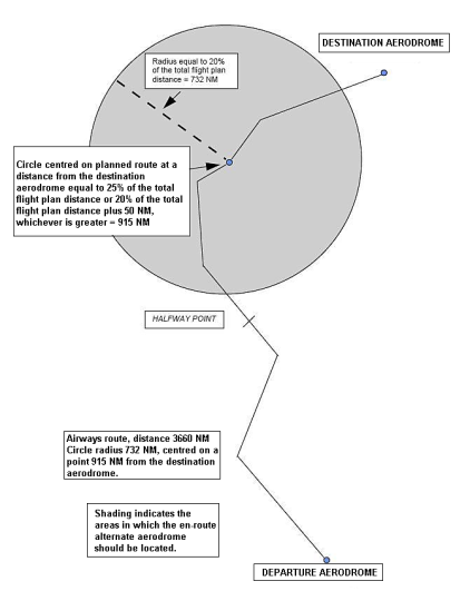
AMC8 CAT.OP.MPA.181 Fuel/energy scheme — fuel/energy planning and in-flight re-planning policy — aeroplanes
ED Decision 2022/005/R
INDIVIDUAL FUEL SCHEME — FUEL CONSUMPTION MONITORING SYSTEM
A fuel consumption monitoring system should be data driven, and should include the following:
(a) a fuel performance monitoring system;
(b) a database that contains statistically significant data of at least 2 years;
(c) statistics and data normalisation; and
(d) data transparency and verification.
GM1 CAT.OP.MPA.181 Fuel/energy scheme — fuel/energy planning and in-flight re-planning policy — aeroplanes
BASIC FUEL SCHEME
TAXI FUEL — LOCAL CONDITIONS
(a) Local conditions, as referred to in point (a) of AMC1 CAT.OP.MPA.181, include NOTAMs, meteorological conditions (e.g. winter operations), ATS procedures (e.g. LVP, collaborative decision-making (CDM)), and any anticipated delay(s).
PLANNING OF FLIGHTS
(b) A flight should be planned by using the most accurate information available. If aircraft-specific data that is derived from a fuel consumption monitoring system is available, this data is used in preference to data that is provided by the aircraft manufacturer. Data that is provided by the aircraft manufacturer should be used only in specific cases, e.g. when introducing a new aircraft type into service.
FUEL CONSUMPTION MONITORING SYSTEM
(c) Extensive guidance on a fuel consumption monitoring system is provided in ICAO Doc 9976 Flight Planning and Fuel Management (FPFM) Manual, Appendix 5 to Chapter 5 Example of a fuel consumption monitoring (FCM) programme (1st Edition, 2015). As a basic requirement, the fuel consumption monitoring system (commonly referred to as ‘hull-specific fuel bias’) is a process of comparing an aeroplane’s achieved in-flight performance to an aeroplane’s predicted performance. Variations between the achieved performance and the predicted performance result in a variation of the fuel consumption rate, which should be accounted for by the operator during flight planning and in-flight re-planning.
The fuel consumption monitoring system is used to determine an individual aeroplane’s performance in comparison with its predicted one. In no case, should data that is collected from one aeroplane be used as a basis for varying another aeroplane’s performance figures away from the predicted values.
The data that is collected and used to determine an aeroplane’s actual performance should be collected in a manner acceptable to the competent authority. The operator should demonstrate that the data collected during in-service operation of the aeroplane is accurate. Where possible, the data should be collected automatically; however, manual recording of data does not preclude an operator from participating in a fuel consumption monitoring system.
ANTICIPATED MASSES — LAST-MINUTE CHANGES
(d) Where appropriate, the operating procedures should include means to revise the fuel quantity and define limits to zero fuel weight (ZFW) changes, beyond which a new operational flight plan should be calculated.
TRIP FUEL — ARRIVAL ROUTING
(e) POINT MERGE PATTERN
When planning for a STAR to point merge, fuel for the direct STAR to the point merge should be included in the trip fuel. The fuel required to account for the probability that part of or the entire point merge route needs to be flown may be included in the contingency fuel unless there is an anticipated delay, in which case, the fuel required for the route should be included in the extra fuel.
(f) POINT TROMBONE PATTERN
When planning for a STAR or transition including a trombone pattern, fuel for the reasonably expected route should be included in the trip fuel. The fuel required to account for the probability that an extended part of or the entire trombone pattern route needs to be flown may be included in the contingency fuel unless there is an anticipated delay, in which case, the fuel required for the trombone pattern route should be included in the extra fuel.
UNFORESEEN FACTORS
(g) According to its definition, contingency fuel is the amount of fuel required to compensate for unforeseen factors.
Unforeseen factors are those that could have an influence on the fuel consumption to the destination aerodrome, such as deviations of an individual aeroplane from the expected fuel consumption data, deviations from forecast meteorological conditions, extended unexpected delays in flight, extended unexpected taxi times, and deviations from planned routings and/or cruising levels.
Unforeseen factors may differ based on the type of fuel scheme adopted by each operator; the higher the capability of the operator, the fewer unforeseen factors there may be.
For example, operators that have a fuel consumption monitoring system should calculate the trip fuel based on the individual fuel consumption. Extended unexpected delays or deviations from forecast meteorological conditions are mitigated by means of statistical data.
DESTINATION ALTERNATE AERODROME
(h) The departure aerodrome may be selected as the destination alternate aerodrome.
FINAL RESERVE FUEL
(i) The operator may determine conservative (rounded-up) FRF values for each type and variant of aeroplane that is used in operations. The intent of this recommendation is:
(1) to provide a reference value for comparing to pre-flight fuel planning computations, and for the purpose of a ‘gross error’ check; and
(2) to provide flight crews with easily referenced and recallable FRF figures to support in‑flight fuel monitoring and decision-making activities.
ANTICIPATED DELAYS
(j) In the context of fuel schemes, an anticipated delay is defined as one that can be predicted based on the information that is provided by the State of the aerodrome and/or ATS provider before the flight commences. For example, restrictions due to scheduled maintenance work on a runway are likely to cause a delay to the normal flow of inbound traffic. That delay may be promulgated either through NOTAMs or via the aeronautical information publication (AIP), including a specific time and/or date.
Another example is an ATS procedure that requires an operator to fly longer routes, e.g. due to curfew during night-time.
DISCRETIONARY FUEL
(k) Discretionary fuel is defined as ‘fuel at the sole discretion of the commander’ (PIC). The commander’s discretion over the amount of fuel to be carried is independent and cannot be encouraged or discouraged.
IN-FLIGHT RE-PLANNING
(l) In the context of fuel policy, in-flight re-planning means voluntarily changing the destination aerodrome, any alternate aerodrome, or the remainder of the route after the flight commences, even when the flight can be completed as originally planned. In-flight re-planning has a broader sense than being obliged to change the intended course of action due to safety issues (remaining fuel, failures, bad weather conditions, etc.). In-flight re-planning allows the operator to modify the filed flight plan after flight commencement for commercial or other reasons. However, the modified flight plan should fulfil all requirements of a new flight plan. The use of en route alternate (ERA) aerodromes to save fuel should comply with the in-flight re-planning requirements.
In-flight re-planning should not apply when the aircraft no longer continues via the flight plan route to the intended destination for reasons that could not be anticipated. In such cases, the in-flight fuel management policy dictates the commander’s course of action.
GM2 CAT.OP.MPA.181 Fuel/energy scheme — fuel/energy planning and in-flight re-planning policy — aeroplanes
ED Decision 2022/005/R
BASIC FUEL SCHEME WITH VARIATIONS — STATISTICAL CONTINGENCY FUEL METHOD
As an example of statistical contingency fuel, the following statistical values of the deviation from the planned to the actual trip fuel provide appropriate statistical coverage:
(a) 99 % coverage plus 3 % of the trip fuel if the calculated flight time:
(1) is less than 2 hours; or
(2) is more than 2 hours and no fuel ERA aerodrome is available;
(b) 99 % coverage if the calculated flight time is more than 2 hours and a fuel ERA aerodrome is available; and
(c) 90 % coverage if:
(1) the calculated flight time is more than 2 hours;
(2) a fuel ERA aerodrome is available; and
(3) at the destination aerodrome, two separate runways are available and usable, one of which is suitable for type B instrument approach operations, and the meteorological conditions are in accordance with point CAT.OP.MPA.182(e).
GM3 CAT.OP.MPA.181 Fuel/energy scheme — fuel/energy planning and in-flight re-planning policy — aeroplanes
ED Decision 2022/005/R
INDIVIDUAL FUEL SCHEME — FUEL CONSUMPTION MONITORING SYSTEM
More information can be found in ICAO Doc 9976 Flight Planning and Fuel Management (FPFM) Manual, Appendix 5 to Chapter 5.
GM4 CAT.OP.MPA.181 Fuel/energy scheme — fuel/energy planning and in-flight re-planning policy — aeroplanes
ED Decision 2022/005/R
INDIVIDUAL FUEL SCHEME — ANTICIPATED METEOROLOGICAL CONDITIONS
When determining the extent of the deviation in the area of operation, the operator should monitor the reliability of the meteorological forecast reports. The competent authority should consider restricting or even not allowing a deviation when reliable meteorological information is not available. To this end, tools to predict and improve the reliability of the meteorological forecast reports may be explored to allow for the intended deviation.
CAT.OP.MPA.182 Fuel/energy scheme – aerodrome selection policy – aeroplanes
Regulation (EU) 2021/1296
(a) At the planning stage, the operator shall ensure that once the flight has commenced, there is reasonable certainty that an aerodrome where a safe landing can be made will be available at the estimated time of use of that aerodrome.
(b) At the planning stage, to allow for a safe landing in case of an abnormal or emergency situation after take-off, the operator shall select and specify in the operational flight plan a take-off alternate aerodrome if either:
(1) the meteorological conditions at the aerodrome of departure are below the operator’s established aerodrome landing minima for that operation; or
(2) it would be impossible to return to the aerodrome of departure for other reasons.
(c) The take-off alternate aerodrome shall be located within a distance from the departure aerodrome that minimises the risk of exposure to potential abnormal or emergency situations. In selecting the take-off alternate aerodrome, the operator shall consider at least the following:
(1) actual and forecast meteorological conditions;
(2) availability and quality of the aerodrome infrastructure;
(3) navigation and landing capabilities of the aircraft in abnormal or emergency conditions, taking into account the redundancy of critical systems; and
(4) approvals held (e.g. extended range operations with two-engined aeroplanes (ETOPS), low visibility operation (LVO), etc.).
(d) At the planning stage, for each instrument flight rules (IFR) flight, the operator shall select and specify in the operational and air traffic services (ATS) flight plans one or more aerodromes so that two safe-landing options are available during normal operation when:
(1) reaching the destination aerodrome; or
(2) reaching the point of no return, to any available fuel/energy ERA aerodrome during isolated aerodrome operations; a flight to an isolated aerodrome shall not be continued past the point of no return unless a current assessment of meteorological conditions, traffic, and other operational conditions indicates that a safe landing can be made at the destination aerodrome at the estimated time of use.
The operator shall obtain prior approval from the competent authority for the use of an isolated aerodrome as destination aerodrome.
(e) The operator shall provide appropriate safety margins to flight planning to take into account a possible deterioration of the available forecast meteorological conditions at the estimated time of landing.
(f) For each IFR flight, the operator shall ensure that sufficient means are available to navigate to and land at the destination aerodrome or at any destination alternate aerodrome in the event of loss of capability for the intended approach and landing operation.
BASIC FUEL SCHEME — TAKE-OFF ALTERNATE AERODROME
The take-off alternate aerodrome should not be farther from the departure aerodrome than:
(a) for two-engined aeroplanes:
(1) 1-hour flight time at an one-engine-inoperative (OEI) cruising speed according to the AFM in ISA and still-air conditions using the actual take-off mass; or
(2) the extended-range twin operations (ETOPS) diversion time that is approved in accordance with Subpart F of Annex V (Part-SPA) to Regulation (EU) No 965/2012, subject to any minimum equipment list (MEL) restriction, up to a maximum of 2-hour flight time at OEI cruising speed according to the AFM in ISA and still-air conditions using the actual take-off mass; and
(b) for three- or four-engined aeroplanes, 2-hour flight time at an all-engines-operating cruising speed according to the AFM in ISA and still-air conditions using the actual take-off mass;
(c) for operations approved in accordance with Annex V (Part-SPA), Subpart L SINGLE-ENGINED TURBINE AEROPLANE OPERATIONS AT NIGHT OR IN IMC (SET-IMC), 30 minutes flying time at normal cruising speed in still-air conditions, based on the actual take-off mass;
(d) in the case of multi-engined aeroplanes, if the AFM does not contain an OEI cruising speed, the speed to be used for calculation shall be that which is achieved with the remaining engine(s) set at maximum continuous power.
AMC2 CAT.OP.MPA.182 Fuel/energy scheme — aerodrome selection policy — aeroplanes
ED Decision 2023/007/R
BASIC FUEL SCHEME — DESTINATION ALTERNATE AERODROME
(a) For each IFR flight, the operator should select and specify in the operational and ATS flight plans at least one destination alternate aerodrome.
(b) For each IFR flight, the operator should select and specify in the operational and ATS flight plans two destination alternate aerodromes when for the selected destination aerodrome, the safety margins for meteorological conditions of AMC5 CAT.OP.MPA.182, and the planning minima of AMC6 CAT.OP.MPA.182 cannot be met, or when no meteorological information is available.
BASIC FUEL SCHEME WITH VARIATIONS — NO DESTINATION ALTERNATE AERODROME
(c) The operator may operate with no destination alternate aerodrome when the destination aerodrome is an isolated aerodrome or when the following two conditions are met:
(1) the duration of the planned flight from take-off to landing does not exceed 6 hours or, in the event of in-flight re-planning, in accordance with point CAT.OP.MPA.181(d), the remaining flying time to destination does not exceed 4 hours; and
(2) two separate runways are usable at the destination aerodrome and the appropriate weather reports and/or weather forecasts indicate that for the period from 1 hour before to 1 hour after the expected time of arrival, the ceiling is at least 2 000 ft (600 m) or the circling height + 500 ft (150 m), whichever is greater, and ground visibility is at least 5 km.
AMC3 CAT.OP.MPA.182 Fuel/energy scheme — aerodrome selection policy — aeroplanes
ED Decision 2022/005/R
BASIC FUEL SCHEME — AERODROME FORECAST METEOROLOGICAL CONDITIONS
Table 1 — Aerodrome forecasts (TAFs) and landing forecasts (TRENDs) to be used for pre-flight planning
|
APPLICATION OF AERODROME FORECASTS (TAF AND TREND) TO PRE-FLIGHT PLANNING |
|||||||
|
(a) APPLICATION OF INITIAL PART OF TAF (1) Application period: from the start of the TAF validity period to the time of applicability of the first subsequent ‘FM…*’ or ‘BECMG’, or if no ‘FM…’ or ‘BECMG’ is given, to the end of the validity period of the TAF. (2) Application of forecast: the forecast of the prevailing weather conditions in the initial part of the TAF should be fully applied, with the exception of mean wind and gusts that should be applied in accordance with the policy under column ‘BECMG AT and FM…’ in the table below. However, this may be temporarily superseded by a ‘TEMPO’ or ‘PROB**’, if applicable according to the table below. |
|||||||
|
(b) APPLICATION OF FORECAST FOLLOWING CHANGE INDICATION IN THE TAF AND TREND |
|||||||
|
TAF or TREND for AERODROME PLANNED AS: |
FM… (alone) and BECMG AT: |
BECMG (alone), BECMG FM, BECMG TL, BECMG FM… TL, in case of: |
TEMPO (alone), TEMPO FM, TEMPO FM… TL, PROB 30/40 (alone) |
PROB TEMPO |
|||
|
Deterioration and improvement |
Deterioration |
Improvement |
Deterioration |
Improvement |
Deterioration and improvement |
||
|
|
|
|
Transient/shower conditions in connection with short‑lived weather phenomena, e.g. thunderstorms, showers |
Persistent conditions in connection with e.g. haze, mist, fog, dust storm/sandstorm, continuous precipitations |
In any case |
|
|
|
DESTINATION at ESTIMATED TIME OF ARRIVAL (ETA) ± 1 HR
TAKE-OFF ALTERNATE at ETA ± 1 HR
DESTINATION ALTERNATE at ETA ± 1 HR
FUEL ERA at ETA ± 1 HR
|
Applicable from the start of change
Mean wind should be within required limits
Gusts exceeding crosswind limits should be fully applied |
Applicable from the start of change
Mean wind should be within required limits
Gusts exceeding crosswind limits should be fully applied |
Applicable from the end of change
Mean wind should be within required limits
Gusts exceeding crosswind limits should be fully applied |
Not applicable
Mean wind and gusts exceeding required limits may be disregarded |
Applicable |
Should be disregarded |
Deterioration may be disregarded. Improvement should be disregarded including mean wind and gusts. |
|
Mean wind should be within required limits |
|||||||
|
Gusts exceeding crosswind limits should be fully applied |
|||||||
|
|
|||||||
|
ETOPS ERA From earliest ETA to ETA + 1 HR |
Applicable from the start of |
Applicable from the start of change |
Applicable from the end of change |
Applicable if below applicable landing minima |
Applicable if below applicable landing minima |
||
|
Mean wind should be within required limits |
Mean wind should be within required limits |
Mean wind should be within required limits |
Mean wind should be within required limits |
Mean wind should be within required limits |
|||
|
Gusts exceeding crosswind limits should be fully applied |
Gusts exceeding crosswind limits should be fully applied |
Gusts exceeding crosswind limits should be fully applied |
Gusts exceeding limits crosswind should be fully applied |
Gusts exceeding limits crosswind should be fully applied |
|||
|
* The space following ‘FM’ should always include a time group, e.g. FM1030. Note 1: ‘required limits’ are those contained in the OM. Note 2: if promulgated aerodrome forecasts do not comply with the provisions of ICAO Annex 3, operators should ensure that guidance on the application of these reports is provided. Note 3: for the definitions of the meteorological terms used in this table, see ICAO Annex 3. |
|||||||
AMC4 CAT.OP.MPA.182 Fuel/energy scheme — aerodrome selection policy — aeroplanes
ED Decision 2022/005/R
BASIC FUEL SCHEME — REACHING THE DESTINATION AERODROME
In the context of the basic fuel scheme and basic fuel scheme with variations, ‘reaching the destination’ means the point at which the aircraft has reached the applicable DA/H or MDA/H at the destination aerodrome.
AMC5 CAT.OP.MPA.182 Fuel/energy scheme — aerodrome selection policy — aeroplanes
ED Decision 2022/005/R
BASIC FUEL SCHEME — SAFETY MARGINS FOR METEOROLOGICAL CONDITIONS
(a) The operator should only select an aerodrome as:
(1) take-off alternate aerodrome; or
(2) destination aerodrome
when the appropriate weather reports and/or forecasts indicate that during a period commencing 1 hour before and ending 1 hour after the estimated time of arrival at the aerodrome, the weather conditions will be at or above the applicable landing minima as follows:
(i) RVR or VIS specified in accordance with point CAT.OP.MPA.110; and
(ii) for a type A or a circling operation, ceiling at or above MDH.
(b) The operator should only select an aerodrome as:
(1) destination alternate aerodrome;
(2) fuel ERA aerodrome; or
(3) isolated destination aerodrome
when the appropriate weather reports and/or forecasts indicate that during a period commencing 1 hour before and ending 1 hour after the estimated time of arrival at the aerodrome, the weather conditions will be at or above the planning minima.
(c) For the take-off alternate aerodrome and isolated destination aerodrome, any limitations related to OEI operations should be taken into account.
AMC6 CAT.OP.MPA.182 Fuel/energy scheme — aerodrome selection policy — aeroplanes
ED Decision 2022/005/R
BASIC FUEL SCHEME— PLANNING MINIMA
The operator should select an aerodrome as:
(a) destination alternate aerodrome;
(b) fuel ERA aerodrome; or
(c) isolated destination aerodrome
only when the appropriate weather reports and/or forecasts indicate that the weather conditions will be at or above the planning minima of Table 2 below (any limitations related to OEI operations are also taken into account):
Table 2 — Basic fuel scheme — planning minima — aeroplanes
Destination alternate aerodrome, fuel ERA aerodrome, isolated destination aerodrome
|
Type of approach operation |
Aerodrome ceiling (cloud base or vertical visibility) |
RVR/VIS |
|
Type B instrument approach operations |
DA/H + 200 ft |
RVR/VIS + 800 m |
|
Type A instrument approach operations |
DA/H or MDA/H + 400 ft |
RVR/VIS + 1 500 m |
|
Circling approach operations |
MDA/H + 400 ft |
VIS + 1 500 m |
|
Crosswind planning minima: see Table 1 of AMC3 CAT.OP.MPA.182 |
||
|
Wind limitations should be applied taking into account the runway condition (dry, wet, contaminated). |
||
AMC7 CAT.OP.MPA.182 Fuel/energy scheme — aerodrome selection policy — aeroplanes
ED Decision 2022/005/R
BASIC FUEL SCHEMES WITH VARIATIONS — ISOLATED AERODROME — POINT OF NO RETURN
(a) Unless destination alternate fuel is carried, the operator should use a destination aerodrome as an isolated aerodrome if the alternate fuel plus the FRF that is required to reach the nearest adequate destination alternate aerodrome is more than:
(1) for aeroplanes with reciprocating engines, the amount of fuel required to fly either for 45 minutes plus 15 % of the flying time planned for cruising, including FRF or for 2 hours, whichever is less; or
(2) for turbine-engined aeroplanes, the amount of fuel required to fly for 2 hours with normal cruise consumption above the destination aerodrome, including the FRF.
(b) If the operator’s fuel planning policy includes an isolated aerodrome, a PNR should be determined by a computerised flight-planning system and specified in the operational flight plan. The required usable fuel for pre-flight calculation should be as indicated in points (b)(1) or (b)(2), whichever is greater:
(1) the sum of:
(i) taxi fuel;
(ii) trip fuel from the departure aerodrome to the isolated aerodrome via the PNR;
(iii) contingency fuel that is calculated in accordance with the operator’s current fuel scheme;
(iv) additional fuel, if required, but not less than:
(A) for aeroplanes with reciprocating engines, the fuel to fly either for 45 minutes plus 15 % of the flight time planned for cruising or for 2 hours, whichever is less; or
(B) for turbine-engined aeroplanes, the fuel to fly for 2 hours with normal cruise consumption above the destination aerodrome, including the FRF;
(v) extra fuel if there are anticipated delays or specific operational constraints; and
(vi) discretionary fuel, if required by the commander; or
(2) the sum of:
(i) taxi fuel;
(ii) trip fuel from the departure aerodrome to the fuel ERA PNR aerodrome via the PNR;
(iii) contingency fuel that is calculated in accordance with the operator’s current fuel scheme;
(iv) additional fuel, if required, but not less than:
(A) for aeroplanes with reciprocating engines, fuel to fly for 45 minutes; or
(B) for turbine-engined aeroplanes, fuel to fly for 30 minutes at holding speed at 1 500 ft (450 m) above the fuel ERA aerodrome elevation in standard conditions, which should not be less than the FRF;
(v) extra fuel if there are anticipated delays or specific operational constraints; and
(vi) discretionary fuel, if required by the commander.
AMC8 CAT.OP.MPA.182 Fuel/energy scheme — aerodrome selection policy — aeroplanes
ED Decision 2023/007/R
BASIC FUEL SCHEME WITH VARIATIONS — PLANNING MINIMA
(a) Variations to the basic fuel schemes in the selection of aerodromes in regard to the planning minima are methods to reduce the meteorological margins based on the established mitigating measures.
(b) As a minimum, the operator should:
(1) use a suitable computerised flight-planning system; and
(2) have established an operational control system that includes flight monitoring.
(c) In addition:
(1) the duration of the planned flight from take-off to landing does not exceed 6 hours or, in the event of in-flight re-planning, in accordance with point CAT.OP.MPA.181(d), the remaining flying time to destination does not exceed 4 hours; and
(2) the planned flight should have a minimum flight crew of two pilots.
(d) Additionally, the operator should select an aerodrome as:
(1) a destination alternate aerodrome, or
(2) a fuel ERA aerodrome,
only when the appropriate weather reports and/or forecasts indicate that the weather conditions will be at or above the planning minima of Table 3 below.
Table 3 — Basic fuel scheme with variations — planning minima — aeroplanes
Destination alternate aerodrome, fuel ERA aerodrome
|
Row |
Type of approach operation |
Aerodrome ceiling (cloud base or vertical visibility) |
RVR/VIS |
|
1 |
Type B instrument approach operations |
DA/H + 200 ft |
RVR/VIS + 550 m |
|
2 |
3D Type A instrument approach operations, based on a facility with a system minimum of 200 ft or less |
DA/H+ 200 ft |
RVR/VIS+ 800 m |
|
3 |
Two or more usable type A instrument approach operations***, each based on a separate navigation aid |
DA/H or MDA/H* + 200 ft |
RVR/VIS** + 1 000 m |
|
4 |
Other type A instrument approach operations |
DA/H or MDA/H + 400 ft |
RVR/VIS + 1 500 m |
|
5 |
Circling approach operations |
MDA/H + 400 ft |
VIS + 1 500 m |
|
Crosswind planning minima: see Table 1 of AMC3 CAT.OP.MPA.182 |
|||
|
Wind limitations should be applied taking into account the runway condition (dry, wet, contaminated). |
|||
* The higher of the usable DA/H or MDA/H.
** The higher of the usable RVR or VIS.
*** Compliance with point CAT.OP.MPA.182(f) should be ensured.
Note: The operator may select the most convenient planning minima row. For example, aerodrome with two type A approaches: one ILS CAT I (DA 350 ft/DH250 ft/550 m) another VOR/DME (MDA 650 ft/1 500 m). The operator may use Row 2 instead of Row 3.
AMC9 CAT.OP.MPA.182 Fuel/energy scheme — aerodrome selection policy — aeroplanes
ED Decision 2023/007/R
BASIC FUEL SCHEME WITH VARIATIONS — PLANNING MINIMA
(a) Variations to the basic fuel schemes in the selection of aerodromes in regard to the planning minima are methods to reduce the meteorological margins based on the established mitigating measures.
(b) As a minimum, the operator should:
(1) use a suitable computerised flight-planning system;
(2) hold an approval for low-visibility approach operations for that fleet; and
(3) have established an operational control system that includes flight monitoring.
(c) Additionally, the operator should select an aerodrome as:
(1) destination alternate aerodrome;
(2) fuel ERA aerodrome; or
(3) isolated destination aerodrome
only when the appropriate weather reports and/or forecasts indicate that the weather conditions will be at or above the planning minima of Table 4 below.
Table 4 — Basic fuel scheme with variations — planning minima
Destination alternate aerodrome, fuel ERA aerodrome, isolated destination aerodrome
|
Row |
Type of approach |
Aerodrome ceiling (cloud base or vertical VIS) |
RVR/VIS |
|
1 |
Two or more usable type B instrument approach operations to two separate runways*** |
DA/H* + 100 ft |
RVR** + 300 m |
|
2 |
One usable type B instrument approach operation |
DA/H + 150 ft |
RVR + 450 m |
|
3 |
DA/H + 200 ft |
RVR/VIS + 800 m |
|
|
4 |
Two or more usable type A instrument approach operations ***, each based on a separate navigation aid |
DA/H or MDA/H* + 200 ft |
RVR/VIS** + 1 000 m |
|
5 |
One usable type A instrument approach operation |
DA/H or MDA/H + 400 ft |
RVR/VIS + 1 500 m |
|
6 |
Circling approach operations |
MDA/H + 400 ft |
VIS + 1 500 m |
|
Crosswind planning minima: see Table 1 of AMC3 CAT.OP.MPA.182 |
|||
|
Wind limitations should be applied taking into account the runway condition (dry, wet, contaminated). |
|||
* The higher of the usable DA/H or MDA/H.
** The higher of the usable RVR or VIS.
*** Compliance with point CAT.OP.MPA.182(f) should be ensured.
Note: The operator may select the most convenient planning minima row. For example, aerodrome with two type B approaches: one CAT3 (0 ft/75 m) another CAT1 (200 ft/550 m). The operator may use Row 2 and use CAT3 (0 + 150 ft/75 + 450 m) instead of Row 1 CAT1 (200 + 100 ft/550 + 300 m).
GM1 CAT.OP.MPA.182 Fuel/energy scheme — aerodrome selection policy — aeroplanes
ED Decision 2022/005/R
BASIC FUEL SCHEME
SAFE-LANDING OPTIONS
(a) Point CAT.OP.MPA.182 sets out the safety objectives of the selection of aerodromes policy. This GM expands on the intent of that provision.
ONE SAFE-LANDING OPTION
(b) Point CAT.OP.MPA.182(a) requires the fuel planning and in-flight re-planning policy to ensure that the aircraft can always proceed to at least one aerodrome where landing is possible, even in abnormal operational conditions. This may require additional fuel (point CAT.OP.MPA.181(c)(6)) to reach an en route alternate (ERA) aerodrome in case of engine or pressurisation failure.
ONE OR MORE AERODROMES
(c) Point CAT.OP.MPA.182(d) requires the operator to select one or more aerodromes at the planning stage; the operator may select only one aerodrome, i.e. the destination aerodrome, in compliance with point CAT.OP.MPA.181(c)(4)(ii).
TWO SAFE-LANDING OPTIONS
(d) Point CAT.OP.MPA.182(d) requires that when planning the flight, two safe-landing options are expected to remain available until the flight reaches its destination, where a decision will be made to commit to land or divert. This will typically be a runway at the destination aerodrome itself and a runway at a destination alternate aerodrome.
The requirement may also be satisfied by two landing runways at the destination aerodrome, provided that the risk of a single event (such as an aircraft accident) or meteorological deterioration at that single aerodrome will not eliminate both options.
(e) Point CAT.OP.MPA.182(d) may also be satisfied by two destination alternate aerodromes when the destination aerodrome is not a weather-permissible aerodrome or when there is insufficient weather information at the time of planning.
(f) In the case of an isolated aerodrome, only one safe-landing option exists beyond the point of no return (PNR), therefore, an exception is set out in point CAT.OP.MPA.182(d)(2), where the conditions to proceed beyond the PNR are laid down, and further explained in AMC7 CAT.OP.MPA.182 and in point (b) of AMC2 CAT.OP.MPA.185(a).
SAFETY MARGINS
(f) Point CAT.OP.MPA.182(e) requires operators to apply safety margins to the aerodrome operating minima to mitigate the risk that the destination alternate aerodromes, isolated aerodromes, or fuel ERA aerodromes fall below aerodrome operating minima due to minor unforeseen weather deteriorations.
BASIC FUEL SCHEME WITH VARIATIONS — NORMAL CRUISE CONSUMPTION
In the context of AMC7 CAT.OP.MPA.182 on isolated aerodromes, normal cruise consumption is the consumption of fuel for 2 hours above the isolated aerodrome. These two hours include 30-minute FRF, leaving enough fuel for an approximately 90-minute hold over the destination.
More information is provided in ICAO Doc 9976 Flight Planning and Fuel Management (FPFM) Manual (1st Edition, 2015).
GM3 CAT.OP.MPA.182 Fuel/energy scheme — aerodrome selection policy — aeroplanes
ED Decision 2022/005/R
BASIC FUEL SCHEME WITH VARIATIONS — FACILITIES WITH A SYSTEM MINIMUM OF 200 FT OR LESS
(a) Table 3 in AMC8 CAT.OP.MPA.182 and Table 4 in AMC9 CAT.OP.MPA.182 refer to type A instrument approach operations based on a facility with a system minimum of 200 ft or less. Such facilities include ILS/MLS, GBAS landing system (GLS) and GNSS/SBAS (LPV). The system minima for various facilities are contained in AMC3 CAT.OP.MPA.110, Table 3.
(b) In regard to system minima and type of instrument approach operation (type A or B), the following should be noted:
(1) System minimum is the lowest height to which a facility can be used without visual references. This value is not related to a particular runway or obstacle environment.
(2) The type of instrument approach operations is related to each individual runway with its obstacle environment.
(c) Amongst other things the lowest DH for an instrument approach operation is determined by the system minima for the facility and the obstacle clearance height (OCH). The resulting DH determines the type of approach operation (type A or B). If the DH is 250 ft or more, it will be a type A approach operation; if the DH is less than 250 ft, it will be a type B approach operation. So, while ILS approaches to most runways may be conducted as type B approach operations, difficult obstacle situations, driving up the DH to 250 ft or higher, will result in type A approach operations.
(d) For example, Row 2 of Table 3 in AMC8 CAT.OP.MPA.182 refers to a case where the obstacle situation and associated OCH result in a DH of 250 ft or more, even though the facility involved supports a DH of 200 ft or less.
(e) This GM refers only to DH (not MDH) since facilities with a system minimum of 200 ft or less are only operated with a DH (or DA), not an MDH.
GM4 CAT.OP.MPA.182 Fuel/energy scheme — aerodrome selection policy — aeroplanes
ED Decision 2022/005/R
FUEL SCHEMES — PLANNING MINIMA — INSTRUMENT APPROACH OPERATIONS
An instrument approach operation is considered usable for planning minima (e.g. Tables 2, 3 and 4 in AMC6 CAT.OP.MPA.182, AMC8 CAT.OP.MPA.182 and AMC9 CAT.OP.MPA.182 respectively) when the approach facilities are available, the aircraft is equipped to perform such an approach, the flight crew is accordingly trained, and the runway is available for landing.
GM1 CAT.OP.MPA.182(d)(1) Fuel/energy scheme — aerodrome selection policy — aeroplanes
ED Decision 2022/005/R
INDIVIDUAL FUEL SCHEME — REACHING THE DESTINATION AERODROME
In the context of individual fuel schemes, ‘reaching the destination’ means being as close as possible to the destination, but not necessarily overhead the destination, and no farther than IAF of the planned instrument approach procedure for the destination aerodrome.
AMC1 CAT.OP.MPA.182(f) Fuel/energy scheme — aerodrome selection policy — aeroplanes
ED Decision 2022/012/R
BASIC FUEL SCHEME — DESTINATION AERODROMES — PBN OPERATIONS
(a) To comply with point CAT.OP.MPA.182(f), when the operator intends to use PBN, the operator should select an aerodrome as destination alternate aerodrome only if an instrument approach procedure that does not rely on a GNSS is available either at that aerodrome or at the destination aerodrome.
BASIC FUEL SCHEME — DESTINATION AERODROMES — OPERATIONAL CREDITS
(b) To comply with point CAT.OP.MPA.182(f), when the operator intends to use ‘operational credits’ (e.g. EFVS, SA CAT I, etc.), the operator should select an aerodrome as destination alternate aerodrome only if an approach procedure that does not rely on the same ‘operational credit’ is available either at that aerodrome or at the destination aerodrome.
GM1 CAT.OP.MPA.182(f) Fuel/energy scheme — aerodrome selection policy — aeroplanes
ED Decision 2022/005/R
BASIC FUEL SCHEME — DESTINATION AERODROMES — PBN OPERATIONS
(a) Point (a) of AMC1 CAT.OP.MPA.182(f) applies only to destination alternate aerodromes in flights that require a destination alternate aerodrome. A take-off or an ERA aerodrome with instrument approach procedures that rely on a GNSS may be planned without restrictions. A destination aerodrome with all instrument approach procedures that rely solely on a GNSS may be used without a destination alternate aerodrome if the conditions for a flight without a destination alternate aerodrome are met.
(b) The term ‘sufficient means are available to navigate to and land at’ means that the procedure can be used in the planning stage and should comply with planning minima requirements.
CAT.OP.MPA.185 Fuel/energy scheme – in-flight fuel/energy management policy – aeroplanes
Regulation (EU) 2021/1296
(a) The operator shall establish procedures for in-flight fuel/energy management that ensure:
(1) continual validation of the assumptions made during the planning stage (pre-flight or in‑flight re-planning, or both);
(2) re-analysis and adjustment, if necessary;
(3) that the amount of usable fuel/energy remaining on board is protected and not less than the fuel/energy that is required to proceed to an aerodrome where a safe landing can be made; and
(4) relevant fuel/energy data for the purpose of points (1), (2), and (3) shall be recorded.
(b) The operator shall have procedures in place to require the commander to obtain delay information from a reliable source when unforeseen circumstances may result in landing at the destination aerodrome with less than the final reserve fuel/energy plus any:
(1) fuel/energy to proceed to an alternate aerodrome, if required; or
(2) fuel/energy required to proceed to an isolated aerodrome.
(c) The commander shall advise air traffic control (ATC) of a ‘minimum fuel/energy’ state by declaring ‘MINIMUM FUEL’ when the commander has:
(1) committed to land at a specific aerodrome; and
(2) calculated that any change to the existing clearance to that aerodrome may result in landing with less than the planned final reserve fuel/energy.
(d) The commander shall declare a situation of ‘fuel/energy emergency’ by broadcasting ‘MAYDAY MAYDAY MAYDAY FUEL’ when the usable fuel/energy that is calculated to be available upon landing at the nearest aerodrome where a safe landing can be made is less than the planned final reserve fuel/energy.
GM1 CAT.OP.MPA.185 Fuel/energy scheme — in-flight fuel/energy management policy — aeroplanes
ED Decision 2023/007/R
BASIC FUEL SCHEME
RELEVANT FUEL DATA TO BE RECORDED
(a) The operator may decide at which regular intervals the relevant fuel data should be recorded.
An example of such intervals could be every 30 minutes for short-range flights and every 60 minutes for longer flights.
(b) The operator should record at least the following relevant fuel-related data:
(1) off-block fuel;
(2) take-off fuel if this data can be recorded automatically;
(3) ‘MINIMUM FUEL’ declarations;
(4) ‘MAYDAY MAYDAY MAYDAY FUEL’ declarations;
(5) fuel after touchdown if this data can be recorded automatically; and
(6) on-block fuel.
When an aircraft communications addressing and reporting system (ACARS) is available, the pilot does not need to be the one recording this data.
RELIABLE SOURCE TO OBTAIN DELAY INFORMATION
(c) A reliable source to obtain delay information may be derived from data provided by an air navigation services provider (ANSP) and should have the following characteristics ranked in order of priority:
(1) integrity: provide timely warnings to users when the delay information should not be used;
(2) availability: the time during which the delay information is accessible to the crew;
(3) accuracy: the degree of conformity between the estimated delay and the true delay; the delay information should be communicated with its corresponding gap error, e.g. delay of 15 ± 2 minutes; the gap error should be added to the base value; and
(4) continuity: the capability of the service to provide the delay information without unscheduled interruptions during the intended operation.
‘MINIMUM FUEL’ DECLARATION
(d) The ‘MINIMUM FUEL’ declaration informs the ATC that all planned aerodrome options have been reduced to a specific aerodrome of intended landing. It also informs the ATC that any change to the existing clearance may result in landing with less than the planned FRF. This is not an emergency situation but an indication that an emergency situation is possible, should any additional delay occur.
(e) When committed to land at a specific aerodrome, the commander should take into account any operational factor that may cause a delay to landing, and thus determine whether the aircraft will land with less than the planned FRF, even after receiving clearance from ATC. A change that may cause a delay to landing could be other than the ATC, e.g. a change of weather conditions, etc. If any such factor is likely to result in landing with less than the planned FRF, the commander should declare ‘MINIMUM FUEL’ to ATC.
(f) The pilot should not expect any form of priority handling as a result of a ‘MINIMUM FUEL’ declaration. However, the ATC should advise the flight crew of any additional expected delays, as well as coordinate with other ATC units when transferring the control of the aeroplane, to ensure that the other ATC units are aware of the flight’s fuel state.
(g) Example 1: The aircraft is on the final approach to the destination aerodrome with a single runway, with just the destination alternate fuel plus FRF available. The aircraft ahead has a tyre burst upon landing and has stopped on the runway. The ATC orders the aircraft on final approach to execute a go-around as the destination aerodrome is closed due to a blocked runway. After completing the go-around, the flight crew decides to divert to the destination alternate aerodrome. After the ATC gives clearance for the destination alternate aerodrome and if the calculated fuel upon landing is close to the FRF, the flight crew should declare ‘MINIMUM FUEL’. The flight crew has now committed to land at the destination alternate aerodrome, and any change to the clearance may result in landing there with less than the planned FRF.
(h) Example 2: The aircraft is approaching the clearance limit point, which has a holding pattern operating at this point in time. The ATC gives the aircraft an expected arrival time that would result in a delay of 25 minutes, and the aircraft enters the holding zone. On receiving this information and prior to entering the holding pattern, the remaining fuel is 7-minute contingency fuel plus 25-minute destination alternate fuel plus 30-minute FRF. The weather conditions and aircraft serviceability are such that the flight crew can convert the destination alternate fuel into holding time over the destination aerodrome. When the remaining fuel no longer allows a diversion from the holding pattern, then the flight crew should declare ‘MINIMUM FUEL’. The flight crew has committed to land at the destination aerodrome, and any change to the clearance may result in landing with less than the planned FRF.
(i) Example 3: The aircraft reaches FL 350, which is the cruising flight level on its 5-hour flight. The weather forecast information that was obtained before departure was favourable and, therefore, the commander did not order any discretionary fuel. The destination alternate fuel is sufficient for 25-minute flight time and the destination alternate aerodrome is located beyond the destination aerodrome. For some reason (unexpected severe turbulence, cockpit window crack, etc.), the aircraft has to descend and continue the flight at FL 230, where fuel consumption is higher. In-flight fuel checks and fuel management now show that the destination aerodrome can still be reached but only if in-flight re-planning is done without the destination alternate aerodrome (the destination aerodrome has two runways and good weather, and it is less than 4-hour flight time away, thus meeting the conditions for not requiring an alternate aerodrome). By doing so, the aircraft will arrive at destination for a straight-in approach with exactly the FRF plus 15-minute flight time. During the next 3,5 hours, an ERA aerodrome is available, and the situation is under control. When approaching the destination, the aircraft has to commit to land at the destination aerodrome as there is no other destination alternate aerodrome within 15 minutes of reaching the destination aerodrome. The ATC now informs the pilots that there is a change of landing runway resulting in a 12-minute trip fuel increase. It is time to declare ‘MINIMUM FUEL’.
(j) Several scenarios illustrating circumstances that could lead to a ‘MINIMUM FUEL’ declaration are provided in ICAO Doc 9976 Flight Planning and Fuel Management (FPFM) Manual (1st Edition, 2015) and the EASA Fuel Manual.
ENSURING A SAFE LANDING — FINAL RESERVE FUEL PROTECTION
(k) The objective of the FRF protection is to ensure that a safe landing is made at any aerodrome when unforeseen circumstances may not allow to safely complete the flight, as originally planned.
The commander should always consider first planning a safe-landing option and estimating whether this landing can be performed with more than the FRF. When this estimation indicates that the FRF can no longer be protected, then a fuel emergency should be declared and any landing option explored (e.g. aerodromes not assessed by operators, military aerodromes, closed runways), including deviating from rules, operational procedures, and methods in the interest of safety (as per point CAT.GEN.MPA.105(b)). ICAO Doc 9976 and the EASA Fuel Manual provide further detailed guidance on the development of a comprehensive in-flight fuel management policy and related procedures.
Note: See Annex I (Definitions) to Regulation (EU) No 965/2012 for the definition of ‘safe landing’.
FURTHER GUIDANCE ON PROCEDURES FOR IN-FLIGHT FUEL MANAGEMENT
(l) ICAO Doc 9976 and the EASA Fuel Manual provide guidance on procedures for in-flight fuel management including reanalysis, adjustment, and/or re-planning considerations when a flight begins
AMC1 CAT.OP.MPA.185(a) Fuel/energy scheme — in-flight fuel/energy management policy — aeroplanes
ED Decision 2022/005/R
BASIC FUEL SCHEME — PROCEDURES FOR IN-FLIGHT FUEL MANAGEMENT
(a) In-flight fuel checks
(1) The operator should establish a procedure to ensure that in-flight fuel checks are carried out at regular intervals or at specified points indicated in the operational flight plan (one check at least every 60 minutes).
(2) The remaining usable fuel should be evaluated to:
(i) compare the actual consumption with the planned consumption;
(ii) check that the remaining usable fuel is sufficient to complete the flight, in accordance with point (b); and
(iii) determine the usable fuel that is expected to remain upon landing at the destination aerodrome.
(3) In relation to the recording of relevant data, the operator should:
(i) agree with the competent authority on what constitutes relevant data for the purpose of recoding;
(ii) use the relevant data as safety performance indicators (SPIs) of the current fuel scheme; and
(iii) ensure that the recorded data is stored for at least 2 years.
The operator should establish a procedure for the data to be de-identified to a level that ensures the implementation of a ‘just culture’.
(b) In-flight fuel management
(1) The flight should be conducted to ensure that the usable fuel expected to remain upon landing at the destination aerodrome is not less than:
(i) the required alternate fuel plus the FRF; or
(ii) the FRF if no alternate aerodrome is required.
(2) If an in-flight fuel check shows that the usable fuel expected to remain upon landing at the destination aerodrome is less than:
(i) the required alternate fuel plus the FRF, the commander should request delay information from the ATC, and take into account the prevailing traffic and operational conditions at the destination aerodrome, at the destination alternate aerodrome, and at any other adequate aerodrome, to decide whether to proceed to the destination aerodrome or to divert in order to perform a safe landing with not less than the FRF; or
(ii) the FRF, if no destination alternate aerodrome is required, the commander should take appropriate action and proceed to an aerodrome where a safe landing can be made with not less than the FRF.
(c) The use of fuel after flight commencement for objectives other than the ones originally intended during pre-flight planning should require reanalysis and, if applicable, adjustment of the planned operation.
AMC2 CAT.OP.MPA.185(a) Fuel/energy scheme — in-flight fuel/energy management policy — aeroplanes
ED Decision 2022/005/R
BASIC FUEL SCHEME WITH VARIATIONS — PROCEDURES FOR IN-FLIGHT FUEL MANAGEMENT
(a) In addition to AMC1 CAT.OP.MPA.185(a) and in the context of point (d) of AMC6 CAT.OP.MPA.181, if the RCF procedure is used on a flight to proceed to destination 1 aerodrome, the commander should ensure that the remaining usable fuel at the decision point is at least the total of the following:
(1) trip fuel from the decision point to destination 1 aerodrome;
(2) contingency fuel that is equal to 5 % of the trip fuel from the decision point to destination 1 aerodrome;
(3) destination 1 aerodrome alternate fuel if a destination 1 alternate aerodrome is required;
(4) additional fuel, if required; and
(5) FRF.
(b) In addition to AMC1 CAT.OP.MPA.185(a), on a flight to an isolated aerodrome, the commander should ensure that the remaining usable fuel at the actual PNR is at least the total of the following:
(1) trip fuel from the PNR to the destination isolated aerodrome;
(2) contingency fuel from the PNR to the destination isolated aerodrome; and
(3) the additional fuel required for isolated aerodromes, as described in AMC7 CAT.OP.MPA.182.
AMC3 CAT.OP.MPA.185(a) Fuel/energy scheme — in-flight fuel/energy management policy — aeroplanes
ED Decision 2022/005/R
INDIVIDUAL FUEL SCHEME — COMMITTING TO LAND AT A SPECIFIC AERODROME
The operator should provide relevant safety information to the commander before the commander decides to commit to land at a specific aerodrome.
CAT.OP.MPA.190 Fuel/energy scheme – helicopters
Regulation (EU) 2021/1296
(a) The operator shall establish, implement, and maintain a fuel/energy scheme that comprises:
(1) a fuel/energy planning and in-flight re-planning policy; and
(2) an in-flight fuel/energy management policy.
(b) The fuel/energy scheme shall:
(1) be appropriate for the type(s) of operation performed; and
(2) correspond to the capability of the operator to support its implementation.
(c) The fuel/energy scheme and any change to it shall require prior approval by the competent authority.
CAT.OP.MPA.191 Fuel/energy scheme – Fuel/energy planning and in-flight re-planning policy – helicopters
Regulation (EU) 2021/1296
(a) As part of the fuel/energy scheme, the operator shall establish a fuel/energy planning and in‑flight re-planning policy to ensure that the aircraft carries a sufficient amount of usable fuel/energy to safely complete the planned flight and to allow for deviations from the planned operation.
(b) The operator shall ensure that the fuel/energy planning of flights is based upon at least the following elements:
(1) procedures contained in the operations manual as well as:
(i) current aircraft-specific data derived from a fuel/energy consumption monitoring system; or
(ii) data provided by the aircraft manufacturer; and
(2) the operating conditions under which the flight is to be conducted including:
(i) aircraft fuel/energy consumption data;
(ii) anticipated masses;
(iii) anticipated meteorological conditions;
(iv) the effects of deferred maintenance items or of configuration deviations, or both; and
(v) procedures and restrictions introduced by air navigation service providers.
(c) The operator shall ensure that the pre-flight calculation of the usable fuel/energy that is required for a flight includes:
(1) taxi fuel/energy, which shall not be less than the amount expected to be used prior to take-off;
(2) trip fuel/energy;
(3) contingency fuel/energy;
(4) destination alternate fuel/energy if a destination alternate aerodrome is required;
(5) final reserve fuel/energy, which shall not be less than:
(i) if flying under visual flight rules (VFR) and navigating by day with reference to visual landmarks, 20-minute fuel/energy at best-range speed; or
(ii) if flying under VFR and navigating by means other than by reference to visual landmarks or at night, 30-minute fuel/energy at best-range speed; or
(iii) if flying under instrument flight rules (IFR), 30-minute fuel/energy at holding speed at 1 500 ft (450m) above the aerodrome elevation in standard conditions, calculated according to the helicopter estimated mass on arrival at the destination alternate aerodrome or at the destination aerodrome when no destination alternate aerodrome is required;
(6) extra fuel/energy, to take into account anticipated delays or specific operational constraints; and
(7) discretionary fuel/energy, if required by the commander.
(d) The operator shall ensure that if a flight has to proceed along a route or to a destination aerodrome other than the ones originally planned, in-flight re-planning procedures for calculating the required usable fuel/energy include:
(1) trip fuel/energy for the remainder of the flight;
(2) reserve fuel/energy consisting of:
(i) contingency fuel/energy;
(ii) alternate fuel/energy if a destination alternate aerodrome is required;
(iii) final reserve fuel/energy; and
(iv) additional fuel/energy, if required by the type of operation;
(3) extra fuel/energy, to take into account anticipated delays or specific operational constraints; and
(4) discretionary fuel/energy, if required by the commander.
(e) As an alternative to points (b) to (d), for helicopters with a maximum certified take-off mass (MCTOM) of 3 175 kg or less, flying by day and over routes navigated by reference to visual landmarks, or for local helicopter operations (LHO), the fuel/energy policy shall ensure that on completion of the flight, or series of flights, the final reserve fuel/energy is sufficient for:
(1) 30-minute flying time at best-range speed; or
(2) 20-minute flying time at best-range speed, if operating within an area providing continuous and suitable operating sites.
AMC1 CAT.OP.MPA.191(b)&(c) Fuel/energy scheme — fuel/energy planning and in-flight re-planning policy —helicopters
ED Decision 2022/005/R
PLANNING CRITERIA
(a) The pre-flight calculation of the required usable fuel to be carried on board should include the following:
(1) taxi fuel, which should take into account local conditions at the departure site and the APU consumption;
(2) trip fuel, which should include fuel:
(i) for take-off and climb from the departure site elevation to the initial cruising level/altitude, taking into account the expected departure routing;
(ii) from the top of climb to the top of descent, including any step climb/descent;
(iii) from the top of descent to the point where the approach procedure is initiated, taking into account the expected arrival procedure; and
(iv) for the approach and landing at the destination site;
(3) contingency fuel, which should be:
(i) for IFR flights, or for VFR flights in a hostile environment, 10 % of the planned trip fuel; or
(ii) for VFR flights in a non-hostile environment, 5 % of the planned trip fuel;
(4) alternate fuel, which should be:
(i) fuel for a missed approach from the applicable DA/H or MDA/H at the destination to the missed-approach altitude, taking into account the complete missed approach procedure;
(ii) fuel for climb from the missed approach altitude to the cruising level/altitude;
(iii) fuel for the cruise from the top of climb to the top of descent;
(iv) fuel for descent from the top of descent to the point where the approach is initiated, taking into account the expected arrival procedure;
(v) fuel for the approach and landing at the destination alternate that is selected in accordance with point CAT.OP.MPA.192; and
(vi) for helicopters operating to or from helidecks that are located in a hostile environment, 10 % of points (a)(4)(i) to (a)(4)(v);
(5) FRF;
(6) extra fuel if there are anticipated delays or specific operational constraints; and
(7) discretionary fuel, which should be at the sole discretion of the commander.
(b) Reduced contingency fuel (RCF) IFR procedure
If the operator’s fuel scheme includes pre-flight planning to a destination 1 aerodrome (commercial destination) with an RCF procedure using a decision point along the route and a destination 2 aerodrome (optional refuelling destination), the pre-flight calculation of the required usable fuel should be according to points (b)(1) or (b)(2), whichever is greater:
(1) the sum of:
(i) taxi fuel;
(ii) trip fuel to the destination 1 aerodrome via the decision point;
(iii) contingency fuel equal to not less than 10 % of the estimated fuel consumption from the decision point to the destination 1 aerodrome;
(iv) alternate fuel;
(v) FRF;
(vi) extra fuel if there are anticipated delays or specific operational constraints; and
(vii) discretionary fuel, which should be at the sole discretion of the commander; or
(2) the sum of:
(i) taxi fuel;
(ii) trip fuel to the destination 2 aerodrome via the decision point;
(iii) contingency fuel equal to not less than 10 % of the estimated fuel consumption from the decision point to the destination 2 aerodrome;
(iv) alternate fuel, if a destination 2 alternate aerodrome is required;
(v) FRF;
(vi) extra fuel if there are anticipated delays or specific operational constraints; and
(vii) discretionary fuel, which should be at the sole discretion of the commander.
(c) Isolated aerodrome IFR procedure
If the operator’s fuel policy includes planning to fly to an isolated aerodrome under IFR or under VFR over routes not navigated by reference to visual landmarks, for which a destination alternate does not exist, the pre-flight calculation of the required usable fuel should include:
(1) taxi fuel;
(2) trip fuel;
(3) contingency fuel calculated in accordance with point (a)(3);
(4) additional fuel to fly for 2 hours at holding speed, including FRF; and
(5) extra fuel if there are anticipated delays or specific operational constraints; and
(6) discretionary fuel, which should be at the sole discretion of the commander.
(d) Sufficient fuel should be carried at all times to ensure that following the failure of an engine that occurs at the most critical point along the route, the helicopter is able to:
(1) descend as necessary and proceed to an adequate aerodrome;
(2) hold for 15 minutes at 1 500 ft (450 m) above aerodrome elevation in standard conditions; and
(3) make an approach and land.
CAT.OP.MPA.192 Selection of aerodromes and operating sites – helicopters
Regulation (EU) 2021/1296
(a) For flights under instrument meteorological conditions (IMC), the operator shall select a take‑off alternate aerodrome within one-hour flying time at normal cruising speed if it is not possible to return to the site of departure for meteorological reasons.
(b) At the planning stage, for each instrument flight rules (IFR) flight, the operator shall select and specify in the operational and air traffic services (ATS) flight plans one or more aerodromes or operating sites so that two safe-landing options are available during normal operation, except as provided for under point SPA.HOFO.120(b).
(c) The operator shall apply appropriate safety margins to flight planning to take into account a possible deterioration of the available forecast meteorological conditions at the estimated time of landing.
(d) For each IFR flight, the operator shall ensure that sufficient means are available to navigate to and land at the destination aerodrome or at any destination alternate aerodrome in the event of loss of capability for the intended approach and landing operation.
AMC1 CAT.OP.MPA.192 Selection of aerodromes and operating sites — helicopters
ED Decision 2022/005/R
PLANNING MINIMA AND SAFETY MARGINS FOR A DESTINATION AERODROME AND SELECTION OF ALTERNATE AERODROMES
(a) When selecting the destination aerodrome, the operator should ensure that one of the following conditions is met:
(1) for a land destination, the duration of the flight and the prevailing meteorological conditions are such that during a period commencing 1 hour before and ending 1 hour after the estimated time of arrival at the aerodrome or operating site, an approach and landing is possible under VMC from the minimum safe altitude at the IAF or before;
(2) for a land destination:
(i) the available current meteorological information indicates that the following meteorological conditions at the destination aerodrome will exist from 2 hours before to 2 hours after the estimated time of arrival, or from the actual time of departure to 2 hours after the estimated time of arrival, whichever is shorter:
(A) a ceiling of at least 120 m (400 ft) above the DA/H or MDA/H of the instrument approach procedure; and
(B) visibility of at least 3 000 m;
(ii) a runway and two published instrument approaches with independent navigation aids are available at the aerodrome of intended landing; and
(iii) fuel planning is based upon the approach procedure that requires the most fuel, and 15-minute fuel is added to the trip fuel;
(3) one destination alternate aerodrome is selected, and the appropriate weather reports and/or forecasts indicate that during a period commencing 1 hour before and ending 1 hour after the estimated time of arrival at the destination, the weather conditions at the destination will be at or above the applicable planning minima as follows:
(i) RVR or VIS specified in accordance with point CAT.OP.MPA.110; and
(ii) for type A instrument approach operations, ceiling at or above (M)DH;
(4) one destination alternate aerodrome is selected, and based on the meteorological information that is obtained in accordance with the procedures of the operations manual (OM), there is a reasonable probability of landing at the destination;
(5) two destination alternate aerodromes are selected; or
(6) the destination aerodrome is isolated, and the appropriate weather reports and/or forecasts indicate that during a period commencing 1 hour before and ending 1 hour after the estimated time of arrival at the destination, the weather conditions at the destination will be at or above the applicable planning minima defined in Table 1.
(b) The operator should specify any alternate aerodrome(s) in the operational flight plan.
(c) If the site of intended landing is isolated and no alternate aerodrome is available, a PNR should be determined.
PLANNING MINIMA FOR DESTINATION ALTERNATE AERODROMES AND ISOLATED AERODROMES
(d) The operator should select the destination alternate aerodrome(s) only if the appropriate weather reports and/or forecasts indicate that during a period commencing 1 hour before and ending 1 hour after the estimated time of arrival at the aerodrome or operating site, the weather conditions will be at or above the applicable planning minima as follows:
(1) if the destination aerodrome is selected by meeting the conditions in points (a)(3) or (a)(5), the planning minima for the destination alternate aerodrome(s) and an isolated aerodrome are as shown in Table 1:
Table 1 — Planning minima for a destination alternate aerodrome and an isolated aerodrome
|
Type of approach |
Planning minima |
|
Type A or type B |
RVR/VIS + 400 m Ceiling at or above (M)DH + 200 ft |
|
VFR or visual approach |
VFR from a position on the instrument flight path to the destination alternate aerodrome |
or
(2) if the destination aerodrome is selected by meeting the condition in point (a)(4), the planning minima for the destination alternate aerodrome(s) are as shown in Table 2:
Table 2 — Planning minima for a destination alternate aerodrome with a reasonable probability of landing at the destination
|
Type of approach |
Planning minima |
|
Type A or type B |
RVR/VIS + 800 m (M)DH + 400 ft |
|
VFR or visual approach |
VFR from a position on the instrument flight path to the destination alternate aerodrome |
DETERMINATION OF THE METEOROLOGICAL CONDITIONS FOR A SAFE LANDING AT THE DESTINATION
(e) To assess the probability of landing at the destination, when flying under IFR to heliports/operating sites without the meteorological information from a certified service provider, the operator should use supplemental meteorological information, or the operator should select two destination alternates. Such meteorological information is usually available at aerodromes. In Europe, the certification of service providers is based on Annex V (Part-MET) to Regulation (EU) 2017/373. In addition, all the following conditions should be met:
(1) The operator should establish a system for observing and assessing the weather, as well as for distributing meteorological information.
(2) The operator should describe in the OM the system defined in point (1).
(3) The operator should assess the weather at the destination aerodrome, and if different, also at the location of the instrument approach. The assessment should be based on the following:
(i) an appropriate weather forecast at an aerodrome where it is reasonable to expect that the local conditions are not significantly different from the conditions at the destination and the location of the instrument approach;
(ii) if the aerodrome described in point (e)(3)(i) is farther than 15 NM away from the location of the approach and the destination, the following conditions should be met:
(A) supplemental meteorological information should be available and confirm that the current weather conditions at destination and at the location of the instrument approach are expected to remain similar to the conditions at the aerodrome described in point (e)(3)(i); and
(B) low-level area forecasts should confirm that the weather is expected to remain similar at destination and at the aerodrome used for the weather assessment, at the expected time of landing; and
(iii) any risk of adverse local weather condition forecast in the low-level area forecasts and relevant to the destination and the location of the instrument approach.
(4) The following should qualify as supplemental meteorological information:
(i) a reliable, timestamped image from a serviceable digital camera of known location, bearing, and altitude, which shows the weather conditions in the approach path at destination;
(ii) a meteorological observation from a properly trained observer; and
(iii) a report from non-certified automatic weather observation systems to which the operator should apply relevant margins based on the reliability and precision of the system.
(5) The operator should establish that there is a reasonable probability of landing at the destination only if the flight time to the destination and then to the alternate aerodrome is less than 3 hours, and if according to the assessment described in point (e)(3), during a period commencing 1 hour before and ending 1 hour after the estimated time of arrival at the location of the approach, the following conditions are met:
(i) the weather conditions will be at or above the planning minima for the approach; and
(ii) if the location of the approach is different from that of the destination aerodrome, the weather conditions will allow to continue the flight to the destination.
(6) Weather observations from the aerodrome described in point (e)(3)(i), or the supplemental meteorological information that is described in point (e)(4), should be available, be no more than 30 minutes old, and be used to assess approach and landing conditions in accordance with point CAT.OP.MPA.300.
(7) The weather observations or information that are described in point (e)(6) may be transmitted to the flight crew using installed equipment, a T-PED, radio communication with trained personnel, or any equivalent means.
(8) The operator should store the weather assessments established in point (e)(3) and the weather observations referred to in point (e)(6) for a period of 3 months.
(9) In case a landing at the destination is not possible due to the weather, even though it was assessed that it would be, the operator should investigate and take all necessary measures to improve future weather assessments.
AMC1 CAT.OP.MPA.192(a) Selection of aerodromes and operating sites — helicopters
ED Decision 2022/005/R
PLANNING MINIMA FOR TAKE-OFF ALTERNATE AERODROMES
The operator should select an aerodrome or landing site as a take-off alternate aerodrome or landing site only when the appropriate weather reports and/or forecasts indicate that during a period commencing 1 hour before and ending 1 hour after the estimated time of arrival at the take-off alternate aerodrome or landing site, the weather conditions will be at or above the applicable landing minima specified in accordance with point CAT.OP.MPA.110. The ceiling should be taken into account when the only available approach operations are type A. Any limitations related to OEI operations should be also taken into account.
GM1 CAT.OP.MPA.192(c)&(d) Selection of aerodromes and operating sites — helicopters
ED Decision 2022/005/R
METEOROLOGICAL INFORMATION
(a) Meteorological data conforms to ICAO Annex 3 and to Annex V (Part-MET) to Regulation (EU) 2017/373. As the following meteorological data is point specific, caution should be exercised when associating it with nearby aerodromes (or helidecks).
(b) METARs
(1) Routine and special meteorological observations at offshore installations should be made during periods and at a frequency agreed between the competent authority of the meteorological services provider and the operator concerned. They should conform to points MET.TR.200 and MET.TR.205 of Part-MET, including the desirable accuracy of observations, which is specified in GM2 MET.TR.210.
(2) Routine and selected special reports are exchanged between meteorological offices in the METAR (aerodrome routine meteorological report) or SPECI (aerodrome special meteorological report) code forms that are prescribed by the World Meteorological Organization.
(c) Aerodrome forecasts (TAFs)
(1) The aerodrome forecast consists of a concise statement of the expected meteorological conditions at an aerodrome and any significant changes expected to occur during a specified period of validity, which is usually not less than 9 hours, and not more than 30 hours. The forecast includes surface wind, visibility, weather and cloud, and expected changes of one or more of these elements during the period. Additional elements may be included as agreed between the meteorological authority and the operators concerned. Where these forecasts relate to offshore installations, barometric pressure and temperature should be included to facilitate the planning of helicopter landing and take-off performance.
(2) Aerodrome forecasts are most commonly exchanged in the TAF code form, and the detailed description of an aerodrome forecast is promulgated in point MET.TR.220 of Part-MET, together with the operationally desirable accuracy elements that are specified in GM3 MET.TR.220.
(d) Landing forecasts (TRENDS)
(1) The landing forecast consists of a concise statement that indicates any significant changes expected to occur at an aerodrome during the 2-hour period immediately following the time of the observation to which it is appended. It contains one or more of the following meteorological elements: surface wind, visibility, weather phenomena, clouds, and other significant information, such as barometric pressure and temperature, as may be agreed between the meteorological authority and the operators concerned.
(2) The detailed description of the landing forecast is promulgated in point MET.TR.225 of Part-MET, together with the operationally desirable accuracy of the forecast elements. In particular, the value of the observed cloud height and visibility elements should remain within ± 30 % of the forecast values in 90 % of the cases.
(3) Landing forecasts most commonly take the form of a TREND forecast appended to a local routine report, local special report, METAR, or SPECI.
GM2 CAT.OP.MPA.192(c)&(d) Selection of aerodromes and operating sites — helicopters
ED Decision 2022/005/R
SUPPLEMENTAL METEOROLOGICAL INFORMATION USING DIGITAL IMAGERY
(a) One or more digital images from a digital camera may be considered as supplemental meteorological information if the following criteria are met:
(1) the camera has a known altitude, azimuth, elevation, and field of view; if pan, tilt or zoom functions are available, the image includes the elevation, azimuth, and an indication of how much the image is zoomed;
(2) the camera is robustly fixed to a solid surface and protected from deliberate or accidental interference; it is secured from the effects of wind and precipitation;
(3) the digital image contains date and timestamp information or other means to ensure that the image is up to date; and
(4) the digital image has a clearly specified update frequency.
(b) If the operator uses the digital image to assess ceiling and visibility, the operator should document the height, bearing, and distance of clearly distinguishable features, and provide a reference image taken on a clear day with negligible cloud or mist.
(c) The operator may achieve the purpose of point (b) with a selectable reference image or a selectable data layer to be superposed on the image. Any selectable reference image should clearly indicate that it is a reference image, and not a current image.
(d) If the operator uses night-time digital images, the quality of those images should remain sufficient to be compared to the reference image, and the darkness should not obscure the distinguishable features described in point (b). This may be achieved by adapting the camera to the current luminosity.
(e) If the digital image is stamped with the value of one or more weather parameters, there should be a means to ensure that each parameter is up to date and provided by a reliable and functional sensor; otherwise, that parameter should not be displayed.
(f) If the camera is exposed to local meteorological conditions such as the foehn effect, the operator should document these local conditions, or the supplemental meteorological information should only be valid in the immediate vicinity of the camera.
AMC1 CAT.OP.MPA.192(d) Selection of aerodromes and operating sites — helicopters
ED Decision 2023/007/R
PBN OPERATIONS
(a) To comply with CAT.OP.MPA.192(d), when the operator intends to use PBN, the operator should either:
(1) demonstrate that the GNSS is robust against loss of capability; or
(2) select an aerodrome as a destination alternate aerodrome only if an instrument approach procedure that does not rely on a GNSS is available either at that aerodrome or at the destination aerodrome.
GNSS ROBUSTNESS AGAINST LOSS OF CAPABILITY — HELICOPTERS
(b) The operator may demonstrate robustness against the loss of capability of the GNSS if all of the following criteria are met:
(1) At flight planning stage, SBAS or GBAS are expected to be available and used.
(2) The failure of a single receiver or system should not compromise the navigation capability required for the intended instrument approach.
(3) The temporary jamming of all GNSS frequencies should not compromise the navigation capability required for the intended route. The operator should establish a procedure to deal with such cases unless other sensors are available to continue on the intended route.
(4) The duration of a jamming event should be determined as follows:
(i) Considering the average speed and height of a helicopter flight, the duration of a jamming event may be considered to be less than 2 minutes.
(ii) The time needed for the GNSS system to re-start and provide the aircraft position and navigation guidance should also be considered.
(iii) Based on (i) and (ii) above, the operator should establish the duration of the loss of GNSS navigation data due to jamming. This duration should be no less than 3 minutes, and may be no longer than 4 minutes.
(5) The operator should ensure resilience to jamming for the duration determined in (4) above, as follows:
(i) If the altitude of obstacles on both sides of the flight path is higher than the planned altitude for a given segment of the flight, the operator should ensure no excessive drift on either side by relying on navigation sensors such as an inertial system with performance in accordance with the intended function.
(ii) If (i) does not apply and the operator cannot rely on sensors other than GNSS, the operator should develop a procedure to ensure that a drift from the intended route during the jamming event has no adverse consequences on the safety of the flight. This procedure may involve air traffic services.
(6) The operator should ensure that no space weather event is predicted to disrupt the GNSS reliability and integrity at both the destination and the alternate aerodrome.
(7) The operator should verify the availability of RAIM for all phases of flight based on GNSS, including navigation to the alternate aerodrome.
(8) The operator’s MEL should reflect the elements in points (b)(1) and (b)(2).
OPERATIONAL CREDITS
(c) To comply with point CAT.OP.MPA.192(d), when the operator intends to use ‘operational credits’ (e.g. EFVS, SA CAT I, etc.), the operator should select an aerodrome as destination alternate aerodrome only if an approach procedure that does not rely on the same ‘operational credit’ is available either at that aerodrome or at the destination aerodrome.
GM1 CAT.OP.MPA.192(d) Selection of aerodromes and operating sites — helicopters
ED Decision 2022/005/R
DESTINATION AND DESTINATION ALTERNATE AERODROMES — PBN OPERATIONS
(a) AMC1 CAT.OP.MPA.192(d) applies only to destination alternate aerodromes in flights that require a destination alternate aerodrome. A take-off or ERA aerodrome with instrument approach procedures that rely on a GNSS may be planned without restrictions. A destination aerodrome with all instrument approach procedures that rely solely on a GNSS may be used without a destination alternate aerodrome if the conditions for a flight without a destination alternate aerodrome are met.
(b) The term ‘available’ means that the procedure can be used in the planning stage and should comply with planning minima requirements.
GM2 CAT.OP.MPA.192(d) Selection of aerodromes and operating sites — helicopters
ED Decision 2022/012/R
GNSS ROBUSTNESS AGAINST LOSS OF CAPABILITY — HELICOPTERS
(a) Redundancy of on-board systems ensures that no single on-board equipment failure (e.g. antenna, GNSS receiver, FMS, or navigation display failure) results in the loss of the GNSS capability.
(b) Any shadowing of the GNSS signal or jamming of all GNSS frequencies from the ground is expected to be of a very short duration and affect a very small area. Additional sensors or functions, such as inertial coasting, may be used during jamming events. Jamming should be considered on all segments of the intended route, including the approach.
(c) The availability of GNSS signals can be compromised if space weather events cause ‘loss of lock’ conditions and more than one satellite signal may be lost on a given GNSS frequency. Until space weather forecasts are available, the operator may use ‘nowcasts’ as short-term predictions for helicopter flights of short durations.
(d) SBAS also contributes to the mitigation of space weather effects, by both providing integrity messages and correcting ionosphere-induced errors.
(e) Even though SBAS should be available and used, RAIM should remain available autonomously. In case of loss of SBAS, the route and the approach to the destination or alternate aerodrome should still be flown with an available RAIM function.
(f) When available, GNSS based on more than one constellation and more than one frequency may provide better integrity and redundancy regarding failures in the space segment of GNSS, jamming, and resilience to space weather events.
CAT.OP.MPA.195 Fuel/energy scheme – in-flight fuel/energy management policy – helicopters
Regulation (EU) 2021/1296
(a) The operator shall establish procedures to ensure that in-flight fuel/energy checks and fuel/energy management are performed.
(b) The commander shall monitor the amount of usable fuel/energy remaining on board to ensure that it is protected and not less than the fuel/energy that is required to proceed to an aerodrome or operating site where a safe landing can be made.
(c) The commander shall advise air traffic control (ATC) of a ‘minimum fuel/energy’ state by declaring ‘MINIMUM FUEL’ when the commander has:
(1) committed to land at an aerodrome or operating site; and
(2) calculated that any change to the existing clearance to that aerodrome or operating site, or other air traffic delays, may result in landing with less than the planned final reserve fuel/energy.
(d) The commander shall declare a situation of ‘fuel/energy emergency’ by broadcasting ‘MAYDAY MAYDAY MAYDAY FUEL’ when the usable fuel/energy estimated to be available upon landing at the nearest aerodrome or operating site where a safe landing can be made is less than the planned final reserve fuel/energy.
ENSURING A SAFE LANDING FOR COMPLEX MOTOR-POWERED HELICOPTERS IN OTHER THAN LOCAL OPERATIONS
The operator should base in-flight fuel management procedures on the following criteria:
(a) in-flight fuel checks:
(1) the commander should establish a procedure to ensure that in-flight fuel checks are carried out at regular intervals; the remaining usable fuel should be recorded and evaluated to:
(i) compare the actual consumption with the planned consumption;
(ii) check that the remaining usable fuel is sufficient to complete the flight; and
(iii) determine the usable fuel that is expected to remain upon landing at the destination; and
(2) the relevant fuel data should be recorded;
(b) in-flight fuel management:
(1) if an in-flight fuel check shows that the usable fuel that is expected to remain upon landing at the destination is less than the required alternate fuel plus the FRF, the commander should:
(i) divert; or
(ii) replan the flight in accordance with point SPA.HOFO.120(b)(1) unless the commander considers it safer to proceed to the destination; and
(2) at an onshore destination, when two suitable, separate touchdown and lift-off areas are available at the destination, and the expected weather conditions at the destination are as specified for planning in point CAT.OP.MPA.245(a)(2), the commander may permit alternate fuel to be used before landing at the destination; and
(c) if an in-flight fuel check on a flight to an isolated destination shows that the usable fuel expected to remain at the point of the last possible diversion is less than the sum of the following:
(1) trip fuel from the point of the last possible diversion to the destination isolated aerodrome;
(2) contingency fuel; and
(3) FRF, or the additional fuel required for isolated aerodromes,
the commander should either divert or proceed to the destination, provided that at onshore destinations, two suitable, separate touchdown and lift-off areas are available at the destination, and the expected weather conditions at the destination are as specified for planning in point CAT.OP.MPA.245(a).
GM1 CAT.OP.MPA.195 Fuel/energy scheme — in-flight fuel/energy management policy — helicopters
ED Decision 2022/005/R
‘MINIMUM FUEL’ DECLARATION
(a) The ‘MINIMUM FUEL’ declaration informs the ATC that all planned landing-site options have been reduced to a specific aerodrome or operating site of intended landing. It also informs the ATC that no other operating site is available, and that any change to the existing clearance, or air traffic delays, may result in landing with less than the planned FRF. This is not an emergency situation but an indication that an emergency situation is possible, should any additional delay occur.
SAFE LANDING — final reserve fuel PROTECTION
(b) The protection of the FRF is intended to ensure that a safe landing is made at any aerodrome or operating site when unforeseen circumstances may not allow to safely complete the operation, as originally planned.
(c) When the FRF can no longer be protected, then a fuel emergency needs to be declared, as per point CAT.OP.MPA.195(d), and any landing option explored, including deviating from rules, operational procedures, and methods in the interest of safety (as per point CAT.GEN.MPA.105(b)).
(d) The ‘MAYDAY MAYDAY MAYDAY FUEL’ declaration informs the ATC that all available landing options have been reduced to a specific landing site, and that an FRF portion may be consumed prior to landing.
CAT.OP.MPA.200 Special refuelling or defuelling of the aircraft
Regulation (EU) 2021/1296
(a) Special refuelling or defuelling shall only be conducted if the operator:
(1) has performed a risk assessment;
(2) has developed procedures; and
(3) has established a training programme for its personnel involved in such operations.
(b) Special refuelling or defuelling applies to:
(1) refuelling with an engine running or rotors turning;
(2) refuelling/defuelling with passengers embarking, on board, or disembarking; and
(3) refuelling/defuelling with wide-cut fuel.
(c) For aeroplanes, any special refuelling or defuelling procedures and any change to them shall require prior approval by the competent authority.
(d) For helicopters, refuelling procedures with rotors turning and any change to them shall require prior approval by the competent authority.
AMC1 CAT.OP.MPA.200 Special refuelling or defueling of the aircraft
ED Decision 2022/005/R
REFUELLING WITH AN ENGINE RUNNING — AEROPLANES
(a) Refuelling with an engine running should only be conducted:
(1) when there are no other sources of electrical or pneumatic power to start the engine if shut down;
(2) in accordance with the specific procedures established by the type certificate (TC) holder of the aeroplane;
(3) with aeroplanes that use JET A, JET A-1 or TS-1 fuel types or any other fuel type that has a flash point above 38 °C and is approved by the operators’ competent authority;
(4) with no passengers embarking, on board, or disembarking;
(5) with permission from the aerodrome operator; and
(6) in the presence of the aerodrome rescue and firefighting services (RFFSs).
(b) The operator should assess the risks associated with refuelling with an engine running and establish appropriate procedures to be followed by all involved personnel, such as flight crew, cabin crew, and ground operations personnel. These procedures should be specified in the OM.
AMC2 CAT.OP.MPA.200 Special refuelling or defueling of the aircraft
ED Decision 2022/005/R
OPERATIONAL PROCEDURES for REFUELLING WITH AN ENGINE RUNNING — AEROPLANES
(a) To reduce the likelihood of conducting refuelling with an engine running, the operator should include in the MEL an operational procedure for dispatch criteria in case of an unserviceable APU, if applicable, to prevent a flight from being dispatched to an aerodrome where no suitable ground support equipment is available.
(b) Appropriate training should be provided to flight crew and maintenance/ground operations personnel that are involved in refuelling with one engine running, as well as to cabin crew, if present on board.
AMC3 CAT.OP.MPA.200 Special refuelling or defueling of the aircraft
ED Decision 2022/005/R
REFUELLING WITH THE ENGINE(S) RUNNING AND/OR ROTORS TURNING — HELICOPTERS
(a) Refuelling with the engine(s) running and/or rotors turning should only be conducted:
(1) with no passengers or technical-crew members embarking or disembarking;
(2) if the operator of the aerodrome/operating site allows such operations;
(3) in accordance with any specific procedures and limitations in the AFM;
(4) using JET A or JET A-1 fuel types; and
(5) in the presence of the appropriate rescue and firefighting (RFF) facilities or equipment.
(b) In addition, operational procedures in the OM should specify that at least the following precautions are taken:
(1) all necessary information should be exchanged in advance with the aerodrome operator, operating-site operator, and refuelling operator;
(2) the procedures to be used by crew members should be defined;
(3) the procedures to be used by the operator’s ground operations personnel that may be in charge of refuelling or assisting in emergency evacuations should be described;
(4) the operator’s training programmes for crew members and for the operator’s ground operations personnel should be described;
(5) the minimum distance between the helicopter turning parts and the refuelling vehicle or installations should be defined when the refuelling takes place outside an aerodrome or at an aerodrome where there are no such limitations;
(6) besides any RFFSs that are required to be available by aerodrome regulations, an additional handheld fire extinguisher with the equivalent of 5 kg of dry powder should be immediately available and ready for use;
(7) a means for a two-way communication between the crew and the person in charge of refuelling should be defined and established;
(8) if fuel vapour is detected inside the helicopter, or any other hazard arises, refuelling/defuelling should be stopped immediately;
(9) one pilot should stay at the controls, constantly monitor the refuelling, and be ready to shut off the engines and evacuate at all times; and
(10) any additional precautions should be taken, as determined by the risk assessment.
AMC4 CAT.OP.MPA.200 Special refuelling or defueling of the aircraft
ED Decision 2022/005/R
OPERATIONAL PROCEDURES — PASSENGERS ON BOARD for REFUELLING WITH THE ENGINE(S) RUNNING AND/OR ROTORS TURNING — HELICOPTERS
In addition to AMC3 CAT.OP.MPA.200, for refuelling with passengers on board, operational procedures in the OM should specify that at least the following precautions are taken:
(a) the positioning of the helicopter and the corresponding helicopter evacuation strategy should be defined taking into account the wind as well as the refuelling facilities or vehicles;
(b) on a heliport, the ground area beneath the exits that are intended for emergency evacuation should be kept clear;
(c) an additional passenger briefing as well as instructions should be defined, and the ‘No smoking’ signs should be on unless ‘No smoking’ placards are installed;
(d) interior lighting should be set to enable identification of emergency exits;
(e) the use of doors during refuelling should be defined: doors on the refuelling side should remain closed, while doors on the opposite side should remain unlocked or, weather permitting, open, unless otherwise specified in the AFM;
(f) at least one suitable person capable of implementing emergency procedures for firefighting, communications, as well as for initiating and directing an evacuation, should remain at a specified location; this person should not be the qualified pilot at the controls or the person performing the refuelling; and
(g) unless passengers are regularly trained in emergency evacuation procedures, an additional crew member or ground crew member should be assigned to assist in the rapid evacuation of the passengers.
AMC5 CAT.OP.MPA.200 Special refuelling or defueling of the aircraft
ED Decision 2022/005/R
REFUELLING OR DEFUELLING WITH PASSENGERS EMBARKING, ON BOARD OR DISEMBARKING
(a) When passengers are embarking, on board, or disembarking, an aircraft should not be refuelled/defuelled with avgas (aviation gasoline) or wide-cut type fuel or a mixture of these types of fuel.
(b) For all other types of fuel, the necessary precautions should be taken, and the aircraft should be properly manned by qualified personnel that should be ready to initiate and direct an evacuation of the aircraft by the most practical and expeditious means available.
AMC6 CAT.OP.MPA.200 Special refuelling or defueling of the aircraft
ED Decision 2022/005/R
OPERATIONAL PROCEDURES WITH PASSENGERS EMBARKING, ON BOARD OR DISEMBARKING — AEROPLANES
(a) When refuelling/defuelling with passengers on board, ground servicing activities and work inside the aeroplane, such as catering and cleaning, should be conducted in such a manner that they do not create a hazard and allow emergency evacuation through those aisles and exits that are intended for emergency evacuation.
(b) The deployment of integral aeroplane stairs or the opening of emergency exits are not necessarily a prerequisite to refuelling.
(c) Operational procedures should specify that at least the following precautions are taken:
(1) one qualified person should remain at a specified location during refuelling/defuelling operations with passengers on board, and be capable of using emergency procedures for fire protection and firefighting, communications, as well as for initiating and directing an evacuation;
(2) two-way communication should be established and remain available through the aeroplane’s intercommunications system, or other suitable means, between the ground crew that supervises the refuelling and the qualified personnel on board the aeroplane; all involved personnel should remain within easy reach of the intercommunications system;
(3) crew, personnel, and passengers should be warned that refuelling/defuelling will take place;
(4) the ‘FASTEN SEAT BELT’ signs should be off;
(5) ‘NO SMOKING’ signs should be on, together with interior lighting to allow the identification of emergency exits;
(6) passengers should be instructed to unfasten their seat belts and refrain from smoking;
(7) the minimum required number of cabin crew should be on board and prepared for an immediate emergency evacuation;
(8) if fuel vapour is detected inside the aeroplane, or any other hazard arises, refuelling/defuelling should be stopped immediately;
(9) the ground area beneath the exits that are intended for emergency evacuation, as well as slide deployment areas, should be kept clear where stairs are not in position for use in the event of evacuation; and
(10) provision is made for a safe and rapid evacuation.
AMC7 CAT.OP.MPA.200 Special refuelling or defueling of the aircraft
ED Decision 2022/005/R
OPERATIONAL PROCEDURES FOR REFUELLING WITH PASSENGERS DISEMBARKING OR EMBARKING — HELICOPTERS WITH THE ENGINE(S) AND ROTORS STOPPED
When the helicopter engine(s) and rotors are stopped, the efficiency and speed of passengers disembarking from and re-embarking on board helicopters should be such that disembarking before refuelling and re-embarking after refuelling is the general practice, except for HEMS or air ambulance operations. However, if such operations are needed, the operator should refer to AMC3 CAT.OP.MPA.200 and AMC4 CAT.OP.MPA.200. Operational procedures to be described in the OM should specify that at least the relevant precautions referred to in the aforementioned AMC are taken.
AMC8 CAT.OP.MPA.200 Special refuelling or defueling of the aircraft
ED Decision 2022/005/R
REFUELLING OR DEFUELLING WITH WIDE-CUT FUEL
Refuelling/defuelling with wide-cut fuel should be conducted only if the operator has established appropriate procedures, taking into account the high risk of using wide-cut fuel types.
GM1 CAT.OP.MPA.200 Special refuelling or defueling of the aircraft
ED Decision 2022/005/R
OPERATIONAL PROCEDURES for REFUELLING WITH AN ENGINE RUNNING — AEROPLANES
For the purpose of refuelling with an engine running, the operator’s procedures need to be aligned with the specific procedures laid down in the AFM. In case there are no specific procedures for refuelling with an engine running available in the AFM, the operator and the manufacturer may wish to cooperate to establish such procedures.
GM2 CAT.OP.MPA.200 Special refuelling or defueling of the aircraft
ED Decision 2022/005/R
RISK ASSESSMENT for REFUELLING WITH THE ENGINE(S) RUNNING AND/OR ROTORS TURNING — HELICOPTERS
The risk assessment should explain why it is not practical to refuel with the engine(s) and rotors stopped, identify any additional hazards, and describe how the additional risks are controlled. Helicopter emergency medical services (HEMS) and helicopter offshore operations (HOFO) are typical operations where the benefits should outweigh the risks if mitigation measures are taken.
Guidance on safe refuelling practices is contained in ICAO Doc 9137 Airport Services Manual, Parts 1 and 8.
The operators’ risk assessment may include, but not be limited to, the following risks, hazards and mitigation measures:
(a) risk related to refuelling with rotors turning;
(b) risk related to the shutting down of the engines, including the risk of failures during start-up;
(c) environmental conditions, such as wind limitations, displacement of exhaust gases, and blade sailing;
(d) risk related to human factors and fatigue management, especially for single-pilot operations for long periods of time;
(e) risk mitigation, such as the safety features of the fuel installation, RFF capability, number of personnel members available, ease of emergency evacuation of the helicopter, etc.;
(f) assessment of the use of radio transmitting equipment;
(g) determination of the use of passenger seat belts;
(h) review of the portable electronic device (PED) policy; and
(i) if passengers are to disembark, consideration of their disembarking before rather than after the refuelling; and
(j) if passengers are to embark, consideration of their embarking after rather than before the refuelling.
PROCEDURES FOR REFUELLING/DEFUELLING WITH WIDE-CUT FUEL
(a) ‘Wide-cut fuel’ (designated JET B, JP-4 or AVTAG) is an aviation turbine fuel that falls between gasoline and kerosene in the distillation range and consequently, compared to kerosene (JET A or JET A1), it has the properties of higher volatility (vapour pressure), lower flash point and lower freezing point.
(b) Wherever possible, the operator should avoid the use of wide-cut fuel types. If a situation arises such that only wide-cut fuels are available for refuelling/defuelling, operators should be aware that mixtures of wide-cut fuels and kerosene turbine fuels can result in the air/fuel mixture in the tank being in the combustible range at ambient temperatures. The extra precautions set out below are advisable to avoid arcing in the tank due to electrostatic discharge. The risk of this type of arcing can be minimised by the use of a static dissipation additive in the fuel. When this additive is present in the proportions stated in the fuel specification, the normal fuelling precautions set out below are considered adequate.
(c) Wide-cut fuel is considered to be ‘involved’ when it is being supplied or when it is already present in aircraft fuel tanks.
(d) When wide-cut fuel has been used, this should be recorded in the technical log. The next two uplifts of fuel should be treated as though they too involved the use of wide-cut fuel.
(e) When refuelling/defuelling with turbine fuels not containing a static dissipator, and where wide-cut fuels are involved, a substantial reduction on fuelling flow rate is advisable. Reduced flow rate, as recommended by fuel suppliers and/or aeroplane manufacturers, has the following benefits:
(1) it allows more time for any static charge build-up in the fuelling equipment to dissipate before the fuel enters the tank;
(2) it reduces any charge which may build up due to splashing; and
(3) until the fuel inlet point is immersed, it reduces misting in the tank and consequently the extension of the flammable range of the fuel.
(f) The flow rate reduction necessary is dependent upon the fuelling equipment in use and the type of filtration employed on the aeroplane fuelling distribution system. It is difficult, therefore, to quote precise flow rates. Reduction in flow rate is advisable whether pressure fuelling or over-wing fuelling is employed.
(g) With over-wing fuelling, splashing should be avoided by making sure that the delivery nozzle extends as far as practicable into the tank. Caution should be exercised to avoid damaging bag tanks with the nozzle.
CAT.OP.MPA.205 Push back and towing — aeroplanes
Regulation (EU) No 965/2012
Push back and towing procedures specified by the operator shall be conducted in accordance with established aviation standards and procedures.
BARLESS TOWING
(a) Barless towing should be based on the applicable SAE ARP (Aerospace Recommended Practices), i.e. 4852B/4853B/5283/5284/5285 (as amended).
(b) Pre- or post-taxi positioning of the aeroplanes should only be executed by barless towing if one of the following conditions are met:
(1) an aeroplane is protected by its own design from damage to the nose wheel steering system;
(2) a system/procedure is provided to alert the flight crew that damage referred to in (b)(1) may have or has occurred;
(3) the towing vehicle is designed to prevent damage to the aeroplane type; or
(4) the aeroplane manufacturer has published procedures and these are included in the operations manual.
CAT.OP.MPA.210 Crew members at stations
Regulation (EU) No 965/2012
(a) Flight crew members
(1) During take-off and landing each flight crew member required to be on duty in the flight crew compartment shall be at the assigned station.
(2) During all other phases of flight each flight crew member required to be on duty in the flight crew compartment shall remain at the assigned station, unless absence is necessary for the performance of duties in connection with the operation or for physiological needs, provided at least one suitably qualified pilot remains at the controls of the aircraft at all times.
(3) During all phases of flight each flight crew member required to be on duty in the flight crew compartment shall remain alert. If a lack of alertness is encountered, appropriate countermeasures shall be used. If unexpected fatigue is experienced, a controlled rest procedure, organised by the commander, may be used if workload permits. Controlled rest taken in this way shall not be considered to be part of a rest period for purposes of calculating flight time limitations nor used to justify any extension of the duty period.
(b) Cabin crew members
During critical phases of flight, each cabin crew member shall be seated at the assigned station and shall not perform any activities other than those required for the safe operation of the aircraft.
CABIN CREW SEATING POSITIONS
(a) When determining cabin crew seating positions, the operator should ensure that they are:
(1) close to a floor level door/exit;
(2) provided with a good view of the area(s) of the passenger cabin for which the cabin crew member is responsible; and
(3) evenly distributed throughout the cabin, in the above order of priority.
(b) Item (a) should not be taken as implying that, in the event of there being more cabin crew stations than required cabin crew, the number of cabin crew members should be increased.
MITIGATING MEASURES — CONTROLLED REST
(a) This GM addresses controlled rest taken by the minimum certified flight crew. It is not related to planned in-flight rest by members of an augmented crew.
(b) Although flight crew members should stay alert at all times during flight, unexpected fatigue can occur as a result of sleep disturbance and circadian disruption. To cover for this unexpected fatigue, and to regain a high level of alertness, a controlled rest procedure in the flight crew compartment, organised by the commander may be used, if workload permits and a controlled rest procedure is described in the operations manual. ‘Controlled rest’ means a period of time ‘off task’ that may include actual sleep. The use of controlled rest has been shown to significantly increase the levels of alertness during the later phases of flight, particularly after the top of descent, and is considered to be good use of crew resource management (CRM) principles. Controlled rest should be used in conjunction with other on-board fatigue management countermeasures such as physical exercise, bright cockpit illumination at appropriate times, balanced eating and drinking, and intellectual activity.
(c) Controlled rest taken in this way should not be considered to be part of a rest period for the purposes of calculating flight time limitations, nor used to justify any duty period. Controlled rest may be used to manage both sudden unexpected fatigue and fatigue that is expected to become more severe during higher workload periods later in the flight. Controlled rest is not related to fatigue management, which is planned before flight.
(d) Controlled rest periods should be agreed according to individual needs and the accepted principles of CRM; where the involvement of the cabin crew is required, consideration should be given to their workload.
(e) When applying controlled rest procedures, the commander should ensure that:
(1) the other flight crew member(s) is (are) adequately briefed to carry out the duties of the resting flight crew member;
(2) one flight crew member is fully able to exercise control of the aircraft at all times; and
(3) any system intervention that would normally require a cross-check according to multi-crew principles is avoided until the resting flight crew member resumes his/her duties.
(f) Controlled rest procedures should satisfy all of the following criteria:
(1) Only one flight crew member at a time should take rest at his/her station; the restraint device should be used and the seat positioned to minimise unintentional interference with the controls.
(2) The rest period should be no longer than 45 minutes (in order to limit any actual sleep to approximately 30 minutes) to limit deep sleep and associated long recovery time (sleep inertia).
(3) After this 45-minute period, there should be a recovery period of 20 minutes to overcome sleep inertia during which control of the aircraft should not be entrusted to the flight crew member. At the end of this recovery period, an appropriate briefing should be given.
(4) In the case of two-crew operations, means should be established to ensure that the non-resting flight crew member remains alert. This may include:
(i) appropriate alarm systems;
(ii) on-board systems to monitor flight crew activity; and
(iii) frequent cabin crew checks. In this case, the commander should inform the senior cabin crew member of the intention of the flight crew member to take controlled rest, and of the time of the end of that rest; frequent contact should be established between the non-resting flight crew member and the cabin crew by communication means, and the cabin crew should check that the resting flight crew member is awake at the end of the period.
(5) There should be a minimum of 20 minutes between two subsequent controlled rest periods in order to overcome the effects of sleep inertia and allow for adequate briefing.
(6) If necessary, a flight crew member may take more than one rest period, if time permits, on longer sectors, subject to the restrictions above.
(7) Controlled rest periods should terminate at least 30 minutes before the top of descent.
CAT.OP.MPA.215 Use of headset — aeroplanes
Regulation (EU) No 965/2012
(a) Each flight crew member required to be on duty in the flight crew compartment shall wear a headset with boom microphone or equivalent. The headset shall be used as the primary device for voice communications with ATS:
(1) when on the ground:
(i) when receiving the ATC departure clearance via voice communication; and
(ii) when engines are running;
(2) when in flight:
(i) below transition altitude; or
(ii) 10 000 ft, whichever is higher;
and
(3) whenever deemed necessary by the commander.
(b) In the conditions of (a), the boom microphone or equivalent shall be in a position that permits its use for two-way radio communications.
CAT.OP.MPA.216 Use of headset — helicopters
Regulation (EU) No 965/2012
Each flight crew member required to be on duty in the flight crew compartment shall wear a headset with boom microphone, or equivalent, and use it as the primary device to communicate with ATS.
CAT.OP.MPA.220 Assisting means for emergency evacuation
Regulation (EU) No 965/2012
The operator shall establish procedures to ensure that before taxiing, take-off and landing and when safe and practicable to do so, all means of assistance for emergency evacuation that deploy automatically are armed.
CAT.OP.MPA.225 Seats, safety belts and restraint systems
Regulation (EU) No 965/2012
(a) Crew members
(1) During take-off and landing, and whenever decided by the commander in the interest of safety, each crew member shall be properly secured by all safety belts and restraint systems provided.
(2) During other phases of the flight, each flight crew member in the flight crew compartment shall keep the assigned station safety belt fastened while at his/her station.
(b) Passengers
(1) Before take-off and landing, and during taxiing, and whenever deemed necessary in the interest of safety, the commander shall be satisfied that each passenger on board occupies a seat or berth with his/her safety belt or restraint system properly secured.
(2) The operator shall make provisions for multiple occupancy of aircraft seats that is only allowed on specified seats. The commander shall be satisfied that multiple occupancy does not occur other than by one adult and one infant who is properly secured by a supplementary loop belt or other restraint device.
CAT.OP.MPA.230 Securing of passenger compartment and galley(s)
Regulation (EU) No 965/2012
(a) The operator shall establish procedures to ensure that before taxiing, take-off and landing all exits and escape paths are unobstructed.
(b) The commander shall ensure that before take-off and landing, and whenever deemed necessary in the interest of safety, all equipment and baggage are properly secured.
CAT.OP.MPA.235 Life-jackets — helicopters
Regulation (EU) No 965/2012
The operator shall establish procedures to ensure that, when operating a helicopter over water in performance class 3, account is taken of the duration of the flight and conditions to be encountered when deciding if life-jackets are to be worn by all occupants.
CAT.OP.MPA.240 Smoking on board
Regulation (EU) No 965/2012
The commander shall not allow smoking on board:
(a) whenever considered necessary in the interest of safety;
(b) during refuelling and defuelling of the aircraft;
(c) while the aircraft is on the surface unless the operator has determined procedures to mitigate the risks during ground operations;
(d) outside designated smoking areas, in the aisle(s) and lavatory(ies);
(e) in cargo compartments and/or other areas where cargo is carried that is not stored in flame-resistant containers or covered by flame-resistant canvas; and
(f) in those areas of the passenger compartment where oxygen is being supplied.
CAT.OP.MPA.245 Meteorological conditions — all aircraft
Regulation (EU) 2021/2237
(a) On IFR flights, the commander shall only:
(1) commence the flight; or
(2) continue beyond the point from which a revised ATS flight plan applies in the event of in‑flight re-planning,
when information is available indicating that the expected meteorological conditions, at the time of arrival, at the destination and/or required alternate aerodrome(s) are at or above the planning minima.
(b) On IFR flights, the commander shall only continue towards the planned destination aerodrome when the latest information available indicates that, at the expected time of arrival, the meteorological conditions at the destination, or at least one destination alternate aerodrome, are at or above the applicable aerodrome operating minima.
(c) On VFR flights, the commander shall only commence the flight when the appropriate meteorological reports and/or forecasts indicate that the meteorological conditions along the part of the route to be flown under VFR will, at the appropriate time, be at or above the VFR limits.
CAT.OP.MPA.246 Meteorological conditions — aeroplanes
In addition to CAT.OP.MPA.245, on IFR flights with aeroplanes, the commander shall only continue beyond:
(a) the decision point when using the reduced contingency fuel/energy (RCF) procedure; or
(b) point of no return when using the isolated aerodrome procedure,
when information is available indicating that the expected meteorological conditions, at the time of arrival, at the destination and/or required alternate aerodrome(s) are at or above the applicable aerodrome operating minima.
CAT.OP.MPA.247 Meteorological conditions — helicopters
Regulation (EU) 2021/2237
In addition to CAT.OP.MPA.245:
(a) On VFR flights overwater out of sight of land with helicopters, the commander shall only commence take-off when the appropriate meteorological reports and/or forecasts indicate that the ceiling will be above 600 ft by day or 1 200 ft by night.
(b) [deleted with Reg. (EU) 2016/1199]
(c) Flight with helicopters to a helideck or elevated FATO shall only be operated when the mean wind speed at the helideck or elevated FATO is reported to be less than 60 kt.
CAT.OP.MPA.250 Ice and other contaminants — ground procedures
Regulation (EU) No 965/2012
(a) The operator shall establish procedures to be followed when ground de-icing and anti-icing and related inspections of the aircraft are necessary to allow the safe operation of the aircraft.
(b) The commander shall only commence take-off if the aircraft is clear of any deposit that might adversely affect the performance or controllability of the aircraft, except as permitted under (a) and in accordance with the AFM.
TERMINOLOGY
Terms used in the context of de-icing/anti-icing have the meaning defined in the following subparagraphs.
(a) ‘Anti-icing’: the process of protecting the aircraft to prevent contamination due to existing or expected weather, typically by applying anti-icing fluids on uncontaminated aircraft surfaces.
(b) ‘Anti-icing fluid’ includes, but is not limited to, the following:
(1) Typically, Type II, III or IV fluid (neat or diluted), normally applied unheated (*);
(2) Type I fluid/water mixture heated to minimum 60°C at the nozzle.
(*) When de-icing and anti-icing in a one-step process, Type II and Type IV fluids are typically applied diluted and heated.
(c) ‘Clear ice’: a coating of ice, generally clear and smooth, but with some air pockets. It forms on exposed objects, the temperatures of which are at, below or slightly above the freezing temperature, by the freezing of super-cooled drizzle, droplets or raindrops. Clear ice is very difficult to be detected visually.
(d) ‘Cold soaked surface frost (CSSF)’: frost developed on cold soaked aircraft surfaces by sublimation of air humidity. This effect can take place at ambient temperatures above 0° C. Cold soaked aircraft surfaces are more common on aircraft that have recently landed. External surfaces of fuel tanks (e.g. wing skins) are typical areas of CSSF formation (known in this case as cold soaked fuel frost (CSFF)), due to the thermal inertia of very cold fuel that remains on the tanks after landing.
(e) ‘Conditions conducive to aircraft icing on the ground’: freezing fog, freezing precipitation, frost, rain or high humidity (on cold soaked wings), hail, ice pellets, snow or mixed rain and snow, etc.
(f) ‘Contamination’: all forms of frozen or semi-frozen deposits on an aircraft, such as frost, snow, slush or ice.
(g) ‘Contamination check’: a check of the aircraft for contamination to establish the need for de-icing.
(h) ‘De-icing’: the process of eliminating frozen contamination from aircraft surfaces, typically by applying de-icing fluids.
(i) ‘De-icing fluid’: such fluid includes, but is not limited to, the following:
(1) Heated water;
(2) Preferably, Type I fluid (neat or diluted (typically));
(3) Type II, III or IV fluid (neat or diluted).
The de-icing fluid is normally applied heated to ensure maximum efficiency and its freezing point should be at the outside air temperature (OAT) or below.
(j) ‘De-icing/anti-icing’: this is the combination of de-icing and anti-icing performed in either one or two steps.
(k) ‘Ground ice detection system (GIDS)’: a system used during aircraft ground operations to inform the personnel involved in the operation and/or the flight crew about the presence of frost, ice, snow or slush on the aircraft surfaces.
(l) ‘Holdover time (HOT)’: the period of time during which an anti-icing fluid provides protection against frozen contamination to the treated aircraft surfaces. It depends among other variables, on the type and intensity of the precipitation, OAT, wind, the particular fluid (or fluid Type) and aircraft design and aircraft configuration during the treatment.
(m) ‘Liquid water equivalent (LWE) system’: an automated weather measurement system that determines the LWE precipitation rate in conditions of frozen or freezing precipitation. The system provides flight crew with continuously updated information on the fluid protection capability under varying weather conditions.
(n) ‘Lowest operational use temperature (LOUT)’: the lowest temperature at which a fluid has been tested and certified as acceptable in accordance with the appropriate aerodynamic acceptance test whilst still maintaining a freezing point buffer of not less than:
(1) 10°C for a Type I fluid; or
(2) 7°C for Type II, III or IV fluids.
(o) ‘Post-treatment check’, ‘Post- de-icing check’ or ‘Post- de-icing/anti-icing check’: an external check of the aircraft after de-icing and/or anti-icing treatment accomplished by qualified staff and from suitably elevated observation points (e.g. from the de-icing/anti-icing equipment itself or other elevated equipment) to ensure that the aircraft is free from frost, ice, snow, or slush.
(p) ‘Pre-take-off check’: The flight crew should continuously monitor the weather conditions after the de-icing/anti-icing treatment to assess whether the applied holdover time is still appropriate. Within the aircraft’s HOT and prior to take-off, the flight crew should check the aircraft’s wings or representative aircraft surfaces for frozen contaminants.
(q) ‘Pre-take-off contamination check’: a check of the treated surfaces for contamination, performed when the HOT has been exceeded or if any doubt exists regarding the continued effectiveness of the applied anti-icing treatment. It is normally accomplished externally, just before commencement of the take-off run.
ANTI-ICING CODES
(r) Upon completion of the anti-icing treatment, a qualified staff provides the anti-icing code to the flight crew as follows: ‘the fluid Type/the fluid name (except for Type I)/concentration (except for Type I)/local time at start of anti-icing/date (optional)/the statement ‘post- de-icing/anti-icing check completed’ (if check completed). Example:
‘TYPE II / MANUFACTURER, BRAND X / 75% / 1335 / 15FEB20 / POST- DE-ICING/ANTI-ICING CHECK COMPLETED’.
(s) When a two-step de-icing/anti-icing operation has been carried out, the anti-icing code should be determined by the second step fluid.
DE-ICING/ANTI-ICING — PROCEDURES
(a) De-icing and/or anti-icing procedures should take into account manufacturer’s recommendations, including those that are type-specific and cover:
(1) contamination checks, including detection of clear ice and under-wing frost; limits on the thickness/area of contamination published in the AFM or other manufacturers’ documentation should be followed;
(2) procedures to be followed if de-icing and/or anti-icing procedures are interrupted or unsuccessful;
(3) post-treatment checks;
(4) pre-take-off checks;
(5) pre-take-off contamination checks;
(6) the recording of any incidents relating to de-icing and/or anti-icing; and
(7) the responsibilities of all personnel involved in de-icing and/or anti-icing.
(b) Operator’s procedures should ensure the following:
(1) When aircraft surfaces are contaminated by ice, frost, slush or snow, they are de-iced prior to take-off according to the prevailing conditions. Removal of contaminants may be performed with mechanical tools, fluids (including hot water), infrared heat or forced air, taking account of aircraft type-specific provisions.
(2) Account is taken of the wing skin temperature versus OAT, as this may affect:
(i) the need to carry out aircraft de-icing and/or anti-icing; and/or
(ii) the performance of the de-icing/anti-icing fluids.
(3) When freezing precipitation occurs or there is a risk of freezing precipitation occurring that would contaminate the surfaces at the time of take-off, aircraft surfaces should be anti-iced. Anti-icing fluids (neat or diluted) should not be applied at OAT below their LOUT. If both de-icing and anti-icing are required, the procedure may be performed in a one- or two-step process, depending upon weather conditions, available equipment, available fluids and the desired HOT. One-step de-icing/anti-icing means that de-icing and anti-icing are carried out at the same time, using a mixture of de-icing/anti-icing fluid and water. Two-step de-icing/anti-icing means that de-icing and anti-icing are carried out in two separate steps. The aircraft is first de-iced using heated water only or a heated mixture of de-icing/anti-icing fluid and water. After completion of the de-icing operation, a layer of a mixture of de-icing/anti-icing fluid and water, or of de-icing /anti-icing fluid only, is sprayed over the aircraft surfaces. The second step will be taken before the first step fluid freezes (typically within 3 minutes but severe conditions may shorten this) and, if necessary, area by area.
(4) When an aircraft is anti-iced and a longer HOT is needed/desired, the use of a less diluted fluid should be considered.
(5) All restrictions relative to OAT and fluid application (including, but not necessarily limited to, temperature and pressure) published by the fluid manufacturer and/or aircraft manufacturer, are followed. and procedures, limitations and recommendations to prevent the formation of fluid residues are followed.
(6) During conditions conducive to aircraft icing on the ground or after de-icing and/or anti-icing, an aircraft is not dispatched for departure unless it has been given a contamination check or a post-treatment check by a trained and qualified person. This check should cover all treated surfaces of the aircraft and be performed from points offering sufficient visibility to these parts. To ensure that there is no clear ice on suspect areas, it may be necessary to make a physical check (e.g. tactile).
(7) The required entry is made in the technical log.
(8) The commander continually monitors the environmental situation after the performed treatment. Prior to take-off, he/she performs a pre-take-off check, which is an assessment of whether the applied HOT is still appropriate. This pre-take-off check includes, but is not limited to, factors such as precipitation, wind and OAT.
(9) If any doubt exists as to whether a deposit may adversely affect the aircraft’s performance and/or controllability characteristics, the commander should arrange for a re-treatment or a pre-take-off contamination check to be performed in order to verify that the aircraft’s surfaces are free of contamination. Special methods and/or equipment may be necessary to perform this check, especially at night time or in extremely adverse weather conditions. If this check cannot be performed just before take-off, re-treatment should be applied.
(10) When re-treatment is necessary, any residue of the previous treatment should be removed, and a completely new de-icing/anti-icing treatment should be applied.
(11) When a ground ice detection system (GIDS) is used to perform an aircraft surfaces check prior to and/or after a treatment, the use of GIDS by suitably trained personnel should be part of the procedure.
(c) Special operational considerations
(1) When using thickened de-icing/anti-icing fluids, the operator should consider a two-step de-icing/anti-icing procedure, the first step preferably with hot water and/or un-thickened fluids.
(2) The use of de-icing/anti-icing fluids should be in accordance with the aircraft manufacturer’s documentation. This is particularly important for thickened fluids to assure sufficient flow-off during take-off. Avoid applying excessive thickened fluid on the horizontal tail of aircraft with unpowered elevator controls.
(3) The operator should comply with any type-specific operational provision(s), such as an aircraft mass decrease and/or a take-off speed increase associated with a fluid application.
(4) The operator should take into account any flight handling procedures (stick force, rotation speed and rate, take-off speed, aircraft attitude etc.) laid down by the aircraft manufacturer when associated with a fluid application.
(5) The limitations or handling procedures resulting from (c)(3) and/or (c)(4) above should be part of the flight crew pre take-off briefing.
(d) Communications
(1) Before aircraft treatment. When the aircraft is to be treated with the flight crew on board, the flight and personnel involved in the operation should confirm the fluid to be used, the extent of treatment required and any aircraft type-specific procedure(s) to be used. Any other information needed to apply the HOT tables should be exchanged.
(2) Anti-icing code. The operator’s procedures should include an anti-icing code, which indicates the treatment the aircraft has received. This code provides the flight crew with the minimum details necessary to estimate a HOT and confirms that the aircraft is free of contamination.
(3) After treatment. Before reconfiguring or moving the aircraft, the flight crew should receive a confirmation from the personnel involved in the operation that all de-icing and/or anti-icing operations are complete and that all personnel and equipment are clear of the aircraft.
(e) Holdover protection & LWE systems
The operator should publish in the OM, when required, the HOTs in the form of a table or a diagram, to account for the various types of ground icing conditions and the different types and concentrations of fluids used. However, the times of protection shown in these tables are to be used as guidelines only and are normally used in conjunction with the pre-take-off check.
An operator may choose to operate using LWE systems instead of HOT tables whenever the required means for using these systems are in place.
(f) Training
The operator’s initial and recurrent de-icing training programmes (including communication training) for flight crew and for other personnel involved in de-icing operations should include additional training if any of the following is introduced:
(1) a new method, procedure and/or technique;
(2) a new type of fluid and/or equipment; or
(3) a new type of aircraft.
(g) Contracting
When the operator contracts de-icing/anti-icing functions, the operator should ensure that the contractor complies with the operator’s training/qualification procedures, together with any specific procedures in respect of:
(1) roles and responsibilities;
(2) de-icing and/or anti-icing methods and procedures;
(3) fluids to be used, including precautions for storage, preparation for use and chemical incompatibilities;
(4) specific aircraft provisions (e.g. no-spray areas, propeller/engine de-icing, APU operation, etc.);
(5) different checks to be conducted; and
(6) procedures for communications with flight crew and any other third party involved.
(h) Special maintenance considerations
(1) General
The operator should take proper account of the possible side-effects of fluid use. Such effects may include, but are not necessarily limited to, dried and/or re-hydrated residues, corrosion and the removal of lubricants.
(2) Special considerations regarding residues of dried fluids
The operator should establish procedures to prevent or detect and remove residues of dried fluid. If necessary, the operator should establish appropriate inspection intervals based on the recommendations of the airframe manufacturers and/or the operator’s own experience:
(i) Dried fluid residues
Dried fluid residues could occur when surfaces have been treated and the aircraft has not subsequently been flown and has not been subject to precipitation. The fluid may then have dried on the surfaces.
(ii) Re-hydrated fluid residues
Repetitive application of thickened de-icing/anti-icing fluids may lead to the subsequent formation/build-up of a dried residue in aerodynamically quiet areas, such as cavities and gaps. This residue may re-hydrate if exposed to high humidity conditions, precipitation, washing, etc., and increase to many times its original size/volume. This residue will freeze if exposed to conditions at or below 0 °C. This may cause moving parts, such as elevators, ailerons, and flap actuating mechanisms to stiffen or jam in-flight. Re-hydrated residues may also form on exterior surfaces, which can reduce lift, increase drag and stall speed. Re-hydrated residues may also collect inside control surface structures and cause clogging of drain holes or imbalances to flight controls. Residues may also collect in hidden areas, such as around flight control hinges, pulleys, grommets, on cables and in gaps.
(iii) Operators are strongly recommended to obtain information about the fluid dry-out and re-hydration characteristics from the fluid manufacturers and to select products with optimised characteristics.
(iv) Additional information should be obtained from fluid manufacturers for handling, storage, application and testing of their products.
DE-ICING/ANTI-ICING BACKGROUND INFORMATION
Further guidance material on this issue is given in the ICAO Manual of Aircraft Ground De-icing/Anti-icing Operations (Doc 9640).
(a) General
(1) Any deposit of frost, ice, snow or slush on the external surfaces of an aircraft may drastically affect its flying qualities because of reduced aerodynamic lift, increased drag, modified stability and control characteristics. Furthermore, freezing deposits may cause moving parts, such as elevators, ailerons, flap actuating mechanism etc., to jam and create a potentially hazardous condition. Propeller/engine/auxiliary power unit (APU)/systems performance may deteriorate due to the presence of frozen contaminants on blades, intakes and components. Also, engine operation may be seriously affected by the ingestion of snow or ice, thereby causing engine stall or compressor damage. In addition, ice/frost may form on certain external surfaces (e.g. wing upper and lower surfaces, etc.) due to the effects of cold fuel/structures, even in ambient temperatures well above 0 °C.
(2) Procedures established by the operator for de-icing and/or anti-icing are intended to ensure that the aircraft is clear of contamination so that degradation of aerodynamic characteristics or mechanical interference will not occur and, following anti-icing, to maintain the airframe in that condition during the appropriate HOT.
(3) Under certain meteorological conditions, de-icing and/or anti-icing procedures may be ineffective in providing sufficient protection for continued operations. Examples of these conditions are freezing rain, ice pellets and hail snow exceeding certain intensities, high wind velocity, and fast-dropping OAT. No HOT guidelines exist for these conditions.
(4) Material for establishing operational procedures can be found, for example, in:
(i) ICAO Annex 3 ‘Meteorological Service for International Air Navigation’;
(ii) ICAO ‘Manual of Aircraft Ground De-icing/Anti-icing Operations’;
(iii) SAE AS6285 ‘Aircraft Ground Deicing/Anti-Icing Processes’;
(iv) SAE AS6286 ‘Aircraft Ground Deicing/Anti-Icing Training and Qualification Program’;
(iv) SAE AS6332 ‘Aircraft Ground Deicing/Anti-icing Quality Management’;
(v) SAE ARP6257 ‘Aircraft Ground De/Anti-Icing Communication Phraseology for Flight and Ground Crews’;
(vi) FAA Holdover Time Guidelines
(vii) FAA 8900.xxx series Notice ‘Revised FAA-Approved Deicing Program Updates, Winter 20xx-20yy’.
(b) Fluids
(1) Type I fluid: Due to its properties, Type I fluid forms a thin, liquid-wetting film on surfaces to which it is applied which, under certain weather conditions, gives a very limited HOT. For anti-icing purposes the fluid/water mixture should have a freezing point of at least 10 °C below OAT; increasing the concentration of fluid in the fluid/water mix does not provide any extension in HOT.
(2) Type II and Type IV fluids contain thickeners which enable the fluid to form a thicker liquid-wetting film on surfaces to which it is applied. Generally, this fluid provides a longer HOT than Type I fluids in similar conditions.
(3) Type III fluid is a thickened fluid especially intended for use on aircraft with low rotation speeds.
(4) Fluids used for de-icing and/or anti-icing should be acceptable to the operator and the aircraft manufacturer. These fluids normally conform to specifications such as SAE AMS1424 (Type I) or SAE AMS1428 (Types II, III and IV). Use of non-conforming fluids is not recommended due to their characteristics being unknown. The anti-icing and aerodynamic properties of thickened fluids may be seriously degraded by, for example, inappropriate storage, treatment, application, application equipment, age and in case they are applied on top of non-chemically compatible de-icing fluids.
(c) Hold-over protection
(1) Hold-over protection is achieved by a layer of anti-icing fluid remaining on and protecting aircraft surfaces for a period of time. With an one-step de-icing/anti-icing procedure, the HOT begins at the commencement of de-icing/anti-icing. With a two-step procedure, the HOT begins at the commencement of the second (anti-icing) step. The hold-over protection runs out:
(i) at the commencement of the take-off roll (due to aerodynamic shedding of fluid); or
(ii) when frozen deposits start to form or accumulate on treated aircraft surfaces, thereby indicating the loss of effectiveness of the fluid.
(2) The duration of hold-over protection may vary depending on the influence of factors other than those specified in the HOT tables. Guidance should be provided by the operator to take account of such factors, which may include:
(i) atmospheric conditions, e.g. exact type and rate of precipitation, wind direction and velocity, relative humidity and solar radiation; and
(ii) the aircraft and its surroundings, such as aircraft component inclination angle, contour and surface roughness, surface temperature, operation in close proximity to other aircraft (jet or propeller blast) and ground equipment and structures.
(3) HOTs are not meant to imply that flight is safe in the prevailing conditions if the specified HOT has not been exceeded. Certain meteorological conditions, such as freezing drizzle or freezing rain, may be beyond the certification envelope of the aircraft.
CAT.OP.MPA.255 Ice and other contaminants – flight procedures
Regulation (EU) No 965/2012
(a) The operator shall establish procedures for flights in expected or actual icing conditions.
(b) The commander shall only commence a flight or intentionally fly into expected or actual icing conditions if the aircraft is certified and equipped to cope with such conditions.
(c) If icing exceeds the intensity of icing for which the aircraft is certified or if an aircraft not certified for flight in known icing conditions encounters icing, the commander shall exit the icing conditions without delay, by a change of level and/or route, if necessary by declaring an emergency to ATC.
FLIGHT IN EXPECTED OR ACTUAL ICING CONDITIONS — AEROPLANES
(a) In accordance with Article 2(a)5. of Annex IV to Regulation (EC) No 216/2008 (Essential requirements for air operations), in case of flight into known or expected icing conditions, the aircraft must be certified, equipped and/or treated to operate safely in such conditions. The procedures to be established by the operator should take account of the design, the equipment, the configuration of the aircraft and the necessary training. For these reasons, different aircraft types operated by the same company may require the development of different procedures. In every case, the relevant limitations are those which are defined in the AFM and other documents produced by the manufacturer.
(b) The operator should ensure that the procedures take account of the following:
(1) the equipment and instruments which must be serviceable for flight in icing conditions;
(2) the limitations on flight in icing conditions for each phase of flight. These limitations may be imposed by the aircraft’s de-icing or anti-icing equipment or the necessary performance corrections that have to be made;
(3) the criteria the flight crew should use to assess the effect of icing on the performance and/or controllability of the aircraft;
(4) the means by which the flight crew detects, by visual cues or the use of the aircraft’s ice detection system, that the flight is entering icing conditions; and
(5) the action to be taken by the flight crew in a deteriorating situation (which may develop rapidly) resulting in an adverse effect on the performance and/or controllability of the aircraft, due to:
(i) the failure of the aircraft’s anti-icing or de-icing equipment to control a build-up of ice; and/or
(ii) ice build-up on unprotected areas.
(c) Training for dispatch and flight in expected or actual icing conditions. The content of the operations manual should reflect the training, both conversion and recurrent, which flight crew, cabin crew and all other relevant operational personnel require in order to comply with the procedures for dispatch and flight in icing conditions:
(1) For the flight crew, the training should include:
(i) instruction on how to recognise, from weather reports or forecasts which are available before flight commences or during flight, the risks of encountering icing conditions along the planned route and on how to modify, as necessary, the departure and in-flight routes or profiles;
(ii) instruction on the operational and performance limitations or margins;
(iii) the use of in-flight ice detection, anti-icing and de-icing systems in both normal and abnormal operation; and
(iv) instruction on the differing intensities and forms of ice accretion and the consequent action which should be taken.
(2) For the cabin crew, the training should include:
(i) awareness of the conditions likely to produce surface contamination; and
(ii) the need to inform the flight crew of significant ice accretion.
FLIGHT IN EXPECTED OR ACTUAL ICING CONDITIONS — HELICOPTERS
(a) The procedures to be established by the operator should take account of the design, the equipment and the configuration of the helicopter and also of the training which is needed. For these reasons, different helicopter types operated by the same company may require the development of different procedures. In every case, the relevant limitations are those that are defined in the AFM and other documents produced by the manufacturer.
(b) For the required entries in the operations manual, the procedural principles that apply to flight in icing conditions are referred to under Subpart MLR of Annex III (ORO.MLR) and should be cross-referenced, where necessary, to supplementary, type-specific data.
(c) Technical content of the procedures
The operator should ensure that the procedures take account of the following:
(1) CAT.IDE.H.165;
(2) the equipment and instruments that should be serviceable for flight in icing conditions;
(3) the limitations on flight in icing conditions for each phase of flight. These limitations may be specified by the helicopter’s de-icing or anti-icing equipment or the necessary performance corrections which have to be made;
(4) the criteria the flight crew should use to assess the effect of icing on the performance and/or controllability of the helicopter;
(5) the means by which the flight crew detects, by visual cues or the use of the helicopter’s ice detection system, that the flight is entering icing conditions; and
(6) the action to be taken by the flight crew in a deteriorating situation (which may develop rapidly) resulting in an adverse effect on the performance and/or controllability of the helicopter, due to either:
(i) the failure of the helicopter’s anti-icing or de-icing equipment to control a build-up of ice; and/or
(ii) ice build-up on unprotected areas.
(d) Training for dispatch and flight in expected or actual icing conditions
The content of the operations manual, Part D, should reflect the training, both conversion and recurrent, which flight crew, and all other relevant operational personnel will require in order to comply with the procedures for dispatch and flight in icing conditions.
(1) For the flight crew, the training should include:
(i) instruction on how to recognise, from weather reports or forecasts that are available before flight commences or during flight, the risks of encountering icing conditions along the planned route and on how to modify, as necessary, the departure and in-flight routes or profiles;
(ii) instruction on the operational and performance limitations or margins;
(iii) the use of in-flight ice detection, anti-icing and de-icing systems in both normal and abnormal operation; and
(iv) instruction on the differing intensities and forms of ice accretion and the consequent action which should be taken.
(2) For crew members other than flight crew, the training should include;
(i) awareness of the conditions likely to produce surface contamination; and
(ii) the need to inform the flight crew of significant ice accretion.
CAT.OP.MPA.260 Fuel/energy and oil supply
Regulation (EU) 2021/1296
The commander shall only commence a flight or continue in the event of in-flight re-planning, when satisfied that the aircraft carries at least the planned amount of usable fuel/energy and oil to safely complete the flight, taking into account the expected operating conditions.
CAT.OP.MPA.265 Take-off conditions
Regulation (EU) 2021/2237
Before commencing take-off, the commander shall be satisfied that:
(a) the meteorological conditions at the aerodrome or operating site and the condition of the runway/FATO intended to be used will not prevent a safe take-off and departure; and
(b) the selected aerodrome operating minima are consistent with all of the following:
(1) the operative ground equipment;
(2) the operative aircraft systems;
(3) the aircraft performance;
(4) flight crew qualifications.
AMC1 CAT.OP.MPA.265(a) Take-off conditions
ED Decision 2022/012/R
METEOROLOGICAL CONDITIONS FOR TAKE-OFF — RUNWAYS
(a) The commander should not commence take-off unless the weather conditions at the aerodrome of departure are equal to or better than the applicable minima for landing at that aerodrome unless a weather-permissible take-off alternate aerodrome is available.
(b) If the reported VIS is below the minimum specified for take-off and RVR is not reported, then take-off should only be commenced if the commander can determine that the visibility along the take-off runway is equal to or better than the required minimum.
CAT.OP.MPA.270 Minimum flight altitudes
Regulation (EU) No 965/2012
The commander or the pilot to whom conduct of the flight has been delegated shall not fly below specified minimum altitudes except when:
(a) necessary for take-off or landing; or
(b) descending in accordance with procedures approved by the competent authority.
CAT.OP.MPA.275 Simulated abnormal situations in flight
Regulation (EU) No 965/2012
The operator shall ensure that when carrying passengers or cargo the following are not simulated:
(a) abnormal or emergency situations that require the application of abnormal or emergency procedures; or
(b) flight in IMC by artificial means.
CAT.OP.MPA.285 Use of supplemental oxygen
Regulation (EU) No 965/2012
The commander shall ensure that flight crew members engaged in performing duties essential to the safe operation of an aircraft in flight use supplemental oxygen continuously whenever the cabin altitude exceeds 10 000 ft for a period of more than 30 minutes and whenever the cabin altitude exceeds 13 000 ft.
CAT.OP.MPA.290 Ground proximity detection
Regulation (EU) No 965/2012
When undue proximity to the ground is detected by a flight crew member or by a ground proximity warning system, the pilot flying shall take corrective action immediately to establish safe flight conditions.
GM1 CAT.OP.MPA.290 Ground proximity detection
TERRAIN AWARENESS WARNING SYSTEM (TAWS) FLIGHT CREW TRAINING PROGRAMMES
(1) This GM contains performance-based training objectives for TAWS flight crew training.
(2) The training objectives cover five areas: theory of operation; pre-flight operations; general in-flight operations; response to TAWS cautions; and response to TAWS warnings.
(3) The term ‘TAWS’ in this GM means a ground proximity warning system (GPWS) enhanced by a forward-looking terrain avoidance function. Alerts include both cautions and warnings.
(4) The content of this GM is intended to assist operators who are producing training programmes. The information it contains has not been tailored to any specific aircraft or TAWS equipment, but highlights features which are typically available where such systems are installed. It is the responsibility of the individual operator to determine the applicability of the content of this guidance material to each aircraft and TAWS equipment installed and their operation. Operators should refer to the AFM and/or aircraft/flight crew operating manual (A/FCOM), or similar documents, for information applicable to specific configurations. If there should be any conflict between the content of this guidance material and that published in the other documents described above, then information contained in the AFM or A/FCOM will take precedence.
(1) The scope of this GM is designed to identify training objectives in the areas of: academic training; manoeuvre training; initial evaluation; and recurrent qualification. Under each of these four areas, the training material has been separated into those items which are considered essential training items and those that are considered to be desirable. In each area, objectives and acceptable performance criteria are defined.
(2) No attempt is made to define how the training programme should be implemented. Instead, objectives are established to define the knowledge that a pilot operating a TAWS is expected to possess and the performance expected from a pilot who has completed TAWS training. However, the guidelines do indicate those areas in which the pilot receiving the training should demonstrate his/her understanding, or performance, using a real-time, interactive training device, i.e. a flight simulator. Where appropriate, notes are included within the performance criteria which amplify or clarify the material addressed by the training objective.
(c) Performance-based training objectives
(1) TAWS academic training
(i) This training is typically conducted in a classroom environment. The knowledge demonstrations specified in this section may be completed through the successful completion of written tests or by providing correct responses to non-real-time computer-based training (CBT) questions.
(ii) Theory of operation. The pilot should demonstrate an understanding of TAWS operation and the criteria used for issuing cautions and warnings. This training should address system operation. Objective: To demonstrate knowledge of how a TAWS functions. Criteria: The pilot should demonstrate an understanding of the following functions:
(A) Surveillance
(a) The GPWS computer processes data supplied from an air data computer, a radio altimeter, an instrument landing system (ILS)/microwave landing system (MLS)/multi-mode (MM) receiver, a roll attitude sensor, and actual position of the surfaces and of the landing gear.
(b) The forward-looking terrain avoidance function utilises an accurate source of known aircraft position, such as that which may be provided by a flight management system (FMS) or GPS, or an electronic terrain database. The source and scope of the terrain, obstacle and airport data, and features such as the terrain clearance floor, the runway picker, and geometric altitude (where provided) should all be described.
(c) Displays required to deliver TAWS outputs include a loudspeaker for voice announcements, visual alerts (typically amber and red lights), and a terrain awareness display (that may be combined with other displays). In addition, means should be provided for indicating the status of the TAWS and any partial or total failures that may occur.
(B) Terrain avoidance. Outputs from the TAWS computer provides visual and audio synthetic voice cautions and warnings to alert the flight crew about potential conflicts with terrain and obstacles.
(C) Alert thresholds. Objective: To demonstrate knowledge of the criteria for issuing cautions and warnings. Criteria: The pilot should be able to demonstrate an understanding of the methodology used by a TAWS to issue cautions and alerts and the general criteria for the issuance of these alerts, including:
(a) basic GPWS alerting modes specified in the ICAO Standard:
— Mode 1: excessive sink rate;
— Mode 2: excessive terrain closure rate;
— Mode 3: descent after take-off or go-around;
— Mode 4: unsafe proximity to terrain;
— Mode 5: descent below ILS glide slope (caution only); and
(b) an additional, optional alert mode — Mode 6: radio altitude call-out (information only); TAWS cautions and warnings which alert the flight crew to obstacles and terrain ahead of the aircraft in line with or adjacent to its projected flight path (forward-looking terrain avoidance (FLTA) and premature descent alert (PDA) functions).
(D) TAWS limitations. Objective: To verify that the pilot is aware of the limitations of TAWS. Criteria: The pilot should demonstrate knowledge and an understanding of TAWS limitations identified by the manufacturer for the equipment model installed, such as:
(a) navigation should not be predicated on the use of the terrain display;
(b) unless geometric altitude data are provided, use of predictive TAWS functions is prohibited when altimeter subscale settings display ‘QFE’;
(c) nuisance alerts can be issued if the aerodrome of intended landing is not included in the TAWS airport database;
(d) in cold weather operations, corrective procedures should be implemented by the pilot unless the TAWS has in-built compensation, such as geometric altitude data;
(e) loss of input data to the TAWS computer could result in partial or total loss of functionality. Where means exist to inform the flight crew that functionality has been degraded, this should be known and the consequences understood;
(f) radio signals not associated with the intended flight profile (e.g. ILS glide path transmissions from an adjacent runway) may cause false alerts;
(g) inaccurate or low accuracy aircraft position data could lead to false or non-annunciation of terrain or obstacles ahead of the aircraft; and
(h) minimum equipment list (MEL) restrictions should be applied in the event of the TAWS becoming partially or completely unserviceable. (It should be noted that basic GPWS has no forward-looking capability.)
(E) TAWS inhibits. Objective: To verify that the pilot is aware of the conditions under which certain functions of a TAWS are inhibited. Criteria: The pilot should demonstrate knowledge and an understanding of the various TAWS inhibits, including the following means of:
(a) silencing voice alerts;
(b) inhibiting ILS glide path signals (as may be required when executing an ILS back beam approach);
(c) inhibiting flap position sensors (as may be required when executing an approach with the flaps not in a normal position for landing);
(d) inhibiting the FLTA and PDA functions; and
(e) selecting or deselecting the display of terrain information, together with appropriate annunciation of the status of each selection.
(2) Operating procedures. The pilot should demonstrate the knowledge required to operate TAWS avionics and to interpret the information presented by a TAWS. This training should address the following topics:
(i) Use of controls. Objective: To verify that the pilot can properly operate all TAWS controls and inhibits. Criteria: The pilot should demonstrate the proper use of controls, including the following means by which:
(A) before flight, any equipment self-test functions can be initiated;
(B) TAWS information can be selected for display; and
(C) all TAWS inhibits can be operated and what the consequent annunciations mean with regard to loss of functionality.
(ii) Display interpretation. Objective: To verify that the pilot understands the meaning of all information that can be annunciated or displayed by a TAWS. Criteria: The pilot should demonstrate the ability to properly interpret information annunciated or displayed by a TAWS, including the following:
(A) knowledge of all visual and aural indications that may be seen or heard;
(B) response required on receipt of a caution;
(C) response required on receipt of a warning; and
(D) response required on receipt of a notification that partial or total failure of the TAWS has occurred (including annunciation that the present aircraft position is of low accuracy).
(iii) Use of basic GPWS or use of the FLTA function only. Objective: To verify that the pilot understands what functionality will remain following loss of the GPWS or of the FLTA function. Criteria: The pilot should demonstrate knowledge of how to recognise the following:
(A) un-commanded loss of the GPWS function, or how to isolate this function and how to recognise the level of the remaining controlled flight into terrain (CFIT) protection (essentially, this is the FLTA function); and
(B) un-commanded loss of the FLTA function, or how to isolate this function and how to recognise the level of the remaining CFIT protection (essentially, this is the basic GPWS).
(iv) Crew coordination. Objective: To verify that the pilot adequately briefs other flight crew members on how TAWS alerts will be handled. Criteria: The pilot should demonstrate that the pre-flight briefing addresses procedures that will be used in preparation for responding to TAWS cautions and warnings, including the following:
(A) the action to be taken, and by whom, in the event that a TAWS caution and/or warning is issued; and
(B) how multi-function displays will be used to depict TAWS information at take-off, in the cruise and for the descent, approach, landing (and any go-around). This will be in accordance with procedures specified by the operator, who will recognise that it may be more desirable that other data are displayed at certain phases of flight and that the terrain display has an automatic 'pop-up' mode in the event that an alert is issued.
(v) Reporting rules. Objective: To verify that the pilot is aware of the rules for reporting alerts to the controller and other authorities. Criteria: The pilot should demonstrate knowledge of the following:
(A) when, following recovery from a TAWS alert or caution, a transmission of information should be made to the appropriate ATC unit; and
(B) the type of written report that is required, how it is to be compiled, and whether any cross reference should be made in the aircraft technical log and/or voyage report (in accordance with procedures specified by the operator), following a flight in which the aircraft flight path has been modified in response to a TAWS alert, or if any part of the equipment appears not to have functioned correctly.
(vi) Alert thresholds. Objective: To demonstrate knowledge of the criteria for issuing cautions and warnings. Criteria: The pilot should be able to demonstrate an understanding of the methodology used by a TAWS to issue cautions and warnings and the general criteria for the issuance of these alerts, including awareness of the following:
(A) modes associated with basic GPWS, including the input data associated with each; and
(B) visual and aural annunciations that can be issued by TAWS and how to identify which are cautions and which are warnings.
(3) TAWS manoeuvre training. The pilot should demonstrate the knowledge required to respond correctly to TAWS cautions and warnings. This training should address the following topics:
(i) Response to cautions:
(A) Objective: To verify that the pilot properly interprets and responds to cautions. Criteria: The pilot should demonstrate an understanding of the need, without delay:
(a) to initiate action required to correct the condition which has caused the TAWS to issue the caution and to be prepared to respond to a warning, if this should follow; and
(b) if a warning does not follow the caution, to notify the controller of the new position, heading and/or altitude/flight level of the aircraft, and what the commander intends to do next.
(B) The correct response to a caution might require the pilot to:
(a) reduce a rate of descent and/or to initiate a climb;
(b) regain an ILS glide path from below, or to inhibit a glide path signal if an ILS is not being flown;
(c) select more flap, or to inhibit a flap sensor if the landing is being conducted with the intent that the normal flap setting will not be used;
(d) select gear down; and/or
(e) initiate a turn away from the terrain or obstacle ahead and towards an area free of such obstructions if a forward-looking terrain display indicates that this would be a good solution and the entire manoeuvre can be carried out in clear visual conditions.
(ii) Response to warnings. Objective: To verify that the pilot properly interprets and responds to warnings. Criteria: The pilot should demonstrate an understanding of the following:
(A) The need, without delay, to initiate a climb in the manner specified by the operator.
(B) The need, without delay, to maintain the climb until visual verification can be made that the aircraft will clear the terrain or obstacle ahead or until above the appropriate sector safe altitude (if certain about the location of the aircraft with respect to terrain) even if the TAWS warning stops. If, subsequently, the aircraft climbs up through the sector safe altitude, but the visibility does not allow the flight crew to confirm that the terrain hazard has ended, checks should be made to verify the location of the aircraft and to confirm that the altimeter subscale settings are correct.
(C) When the workload permits that, the flight crew should notify the air traffic controller of the new position and altitude/flight level, and what the commander intends to do next.
(D) That the manner in which the climb is made should reflect the type of aircraft and the method specified by the aircraft manufacturer (which should be reflected in the operations manual) for performing the escape manoeuvre. Essential aspects will include the need for an increase in pitch attitude, selection of maximum thrust, confirmation that external sources of drag (e.g. spoilers/speed brakes) are retracted, and respect of the stick shaker or other indication of eroded stall margin.
(E) That TAWS warnings should never be ignored. However, the pilot’s response may be limited to that which is appropriate for a caution, only if:
(a) the aircraft is being operated by day in clear, visual conditions; and
(b) it is immediately clear to the pilot that the aircraft is in no danger in respect of its configuration, proximity to terrain or current flight path.
(4) TAWS initial evaluation:
(i) The flight crew member’s understanding of the academic training items should be assessed by means of a written test.
(ii) The flight crew member’s understanding of the manoeuvre training items should be assessed in a FSTD equipped with TAWS visual and aural displays and inhibit selectors similar in appearance and operation to those in the aircraft which the pilot will fly. The results should be assessed by a synthetic flight instructor, synthetic flight examiner, type rating instructor or type rating examiner.
(iii) The range of scenarios should be designed to give confidence that proper and timely responses to TAWS cautions and warnings will result in the aircraft avoiding a CFIT accident. To achieve this objective, the pilot should demonstrate taking the correct action to prevent a caution developing into a warning and, separately, the escape manoeuvre needed in response to a warning. These demonstrations should take place when the external visibility is zero, though there is much to be learnt if, initially, the training is given in 'mountainous' or 'hilly' terrain with clear visibility. This training should comprise a sequence of scenarios, rather than be included in line oriented flight training (LOFT).
(iv) A record should be made, after the pilot has demonstrated competence, of the scenarios that were practised.
(5) TAWS recurrent training:
(i) TAWS recurrent training ensures that pilots maintain the appropriate TAWS knowledge and skills. In particular, it reminds pilots of the need to act promptly in response to cautions and warnings, and of the unusual attitude associated with flying the escape manoeuvre.
(ii) An essential item of recurrent training is the discussion of any significant issues and operational concerns that have been identified by the operator. Recurrent training should also address changes to TAWS logic, parameters or procedures and to any unique TAWS characteristics of which pilots should be aware.
(6) Reporting procedures:
(i) Verbal reports. Verbal reports should be made promptly to the appropriate air traffic control unit:
(A) whenever any manoeuvre has caused the aircraft to deviate from an air traffic clearance;
(B) when, following a manoeuvre which has caused the aircraft to deviate from an air traffic clearance, the aircraft has returned to a flight path which complies with the clearance; and/or
(C) when an air traffic control unit issues instructions which, if followed, would cause the pilot to manoeuvre the aircraft towards terrain or obstacle or it would appear from the display that a potential CFIT occurrence is likely to result.
(ii) Written reports. Written reports should be submitted in accordance with the operator's occurrence reporting scheme and they also should be recorded in the aircraft technical log:
(A) whenever the aircraft flight path has been modified in response to a TAWS alert (false, nuisance or genuine);
(B) whenever a TAWS alert has been issued and is believed to have been false; and/or
(C) if it is believed that a TAWS alert should have been issued, but was not.
(iii) Within this GM and with regard to reports:
(A) the term 'false' means that the TAWS issued an alert which could not possibly be justified by the position of the aircraft in respect to terrain and it is probable that a fault or failure in the system (equipment and/or input data) was the cause;
(B) the term 'nuisance' means that the TAWS issued an alert which was appropriate, but was not needed because the flight crew could determine by independent means that the flight path was, at that time, safe;
(C) the term 'genuine' means that the TAWS issued an alert which was both appropriate and necessary; and
(D) the report terms described in (c)(6)(iii) are only meant to be assessed after the occurrence is over, to facilitate subsequent analysis, the adequacy of the equipment and the programmes it contains. The intention is not for the flight crew to attempt to classify an alert into any of these three categories when visual and/or aural cautions or warnings are annunciated.
CAT.OP.MPA.295 Use of airborne collision avoidance system (ACAS)
Regulation (EU) 2016/1199
The operator shall establish operational procedures and training programmes when ACAS is installed and serviceable so that the flight crew is appropriately trained in the avoidance of collisions and competent in the use of ACAS II equipment.
GENERAL
(a) The ACAS operational procedures and training programmes established by the operator should take into account this GM. It incorporates advice contained in:
(1) ICAO Doc 8168 (PANS-OPS), Volume III77 ICAO Doc 8168 Procedures for Air Navigation Services-Aircraft Operations, Volume III - Aircraft Operating Procedures, First Edition, 2018. Aircraft Operating Procedures, Chapter 3 and Attachment A (ACAS training guidelines for pilots) and Attachment B (ACAS high vertical rate (HVR) encounters) to Section 4, Chapter 3; and
(2) ICAO PANS-ATM78 ICAO Doc 4444-ATM/501 - PANS-ATM (Procedures for Air Navigation Services-Air Traffic Management) (Fifteenth edition, Amendment 3). Chapters 12 and 15 phraseology requirements;
(3) ICAO Annex 10, Volume IV;
(4) ICAO PANS-ATM.
(b) Additional guidance material on ACAS may be referred to, including information available from such sources as EUROCONTROL.
ACAS FLIGHT CREW TRAINING PROGRAMMES
(c) During the implementation of ACAS, several operational issues were identified which had been attributed to deficiencies in flight crew training programmes. As a result, the issue of flight crew training has been discussed within the ICAO, which has developed guidelines for operators to use when designing training programmes.
(d) This GM contains performance-based training objectives for ACAS II flight crew training. Information contained in this paper related to traffic advisories (TAs) is also applicable to ACAS I and ACAS II users. The training objectives cover five areas: theory of operation; pre-flight operations; general in-flight operations; response to TAs; and response to resolution advisories (RAs).
(e) The information provided is valid for version 7 and 7.1 (ACAS II). Where differences arise, these are identified.
(f) The performance-based training objectives are further divided into the areas of: academic training; manoeuvre training; initial evaluation and recurrent qualification. Under each of these four areas, the training material has been separated into those items which are considered essential training items and those which are considered desirable. In each area, objectives and acceptable performance criteria are defined.
(g) ACAS academic training
(1) This training is typically conducted in a classroom environment. The knowledge demonstrations specified in this section may be completed through the successful completion of written tests or through providing correct responses to non-real-time computer-based training (CBT) questions.
(2) Essential items
(i) Theory of operation. The flight crew member should demonstrate an understanding of ACAS II operation and the criteria used for issuing TAs and RAs. This training should address the following topics:
(A) System operation
Objective: to demonstrate knowledge of how ACAS functions.
Criteria: the flight crew member should demonstrate an understanding of the following functions:
(a) Surveillance
(1) ACAS interrogates other transponder-equipped aircraft within a nominal range of 14 NM.
(2) ACAS surveillance range can be reduced in geographic areas with a large number of ground interrogators and/or ACAS II-equipped aircraft.
(3) If the operator's ACAS implementation provides for the use of the Mode S extended squitter, the normal surveillance range may be increased beyond the nominal 14 NM. However, this information is not used for collision avoidance purposes.
(b) Collision avoidance
(1) TAs can be issued against any transponder-equipped aircraft which responds to the ICAO Mode C interrogations, even if the aircraft does not have altitude reporting capability.
(2) RAs can be issued only against aircraft that are reporting altitude and in the vertical plane only.
(3) RAs issued against an ACAS-equipped intruder are co-ordinated to ensure complementary RAs are issued.
(4) Failure to respond to an RA deprives own aircraft of the collision protection provided by own ACAS.
(5) Additionally, in ACAS-ACAS encounters, failure to respond to an RA also restricts the choices available to the other aircraft's ACAS and thus renders the other aircraft's ACAS less effective than if own aircraft were not ACAS-equipped.
(B) Advisory thresholds
Objective: to demonstrate knowledge of the criteria for issuing TAs and RAs.
Criteria: the flight crew member should demonstrate an understanding of the methodology used by ACAS to issue TAs and RAs and the general criteria for the issuance of these advisories, including the following:
(a) ACAS advisories are based on time to closest point of approach (CPA) rather than distance. The time should be short and vertical separation should be small, or projected to be small, before an advisory can be issued. The separation standards provided by ATS are different from the miss distances against which ACAS issues alerts.
(b) Thresholds for issuing a TA or an RA vary with altitude. The thresholds are larger at higher altitudes.
(c) A TA occurs from 15 to 48 seconds and an RA from 15 to 35 seconds before the projected CPA.
(d) RAs are chosen to provide the desired vertical miss distance at CPA. As a result, RAs can instruct a climb or descent through the intruder aircraft's altitude.
(C) ACAS limitations
Objective: to verify that the flight crew member is aware of the limitations of ACAS.
Criteria: the flight crew member should demonstrate knowledge and understanding of ACAS limitations, including the following:
(a) ACAS will neither track nor display non-transponder-equipped aircraft, nor aircraft not responding to ACAS Mode C interrogations.
(b) ACAS will automatically fail if the input from the aircraft’s barometric altimeter, radio altimeter or transponder is lost.
(1) In some installations, the loss of information from other on board systems such as an inertial reference system (IRS) or attitude heading reference system (AHRS) may result in an ACAS failure. Individual operators should ensure that their flight crews are aware of the types of failure that will result in an ACAS failure.
(2) ACAS may react in an improper manner when false altitude information is provided to own ACAS or transmitted by another aircraft. Individual operators should ensure that their flight crew are aware of the types of unsafe conditions that can arise. Flight crew members should ensure that when they are advised, if their own aircraft is transmitting false altitude reports, an alternative altitude reporting source is selected, or altitude reporting is switched off.
(c) Some aeroplanes within 380 ft above ground level (AGL) (nominal value) are deemed to be ‘on ground’ and will not be displayed. If ACAS is able to determine an aircraft below this altitude is airborne, it will be displayed.
(d) ACAS may not display all proximate transponder-equipped aircraft in areas of high density traffic.
(e) The bearing displayed by ACAS is not sufficiently accurate to support the initiation of horizontal manoeuvres based solely on the traffic display.
(f) ACAS will neither track nor display intruders with a vertical speed in excess of 10 000 ft/min. In addition, the design implementation may result in some short-term errors in the tracked vertical speed of an intruder during periods of high vertical acceleration by the intruder.
(g) Ground proximity warning systems/ground collision avoidance systems (GPWSs/GCASs) warnings and wind shear warnings take precedence over ACAS advisories. When either a GPWS/GCAS or wind shear warning is active, ACAS aural annunciations will be inhibited and ACAS will automatically switch to the 'TA only' mode of operation.
(D) ACAS inhibits
Objective: to verify that the flight crew member is aware of the conditions under which certain functions of ACAS are inhibited.
Criteria: the flight crew member should demonstrate knowledge and understanding of the various ACAS inhibits, including the following:
(a) ‘Increase Descent’ RAs are inhibited below 1 450 ft AGL;
(b) ‘Descend’ RAs are inhibited below 1 100 ft AGL;
(c) all RAs are inhibited below 1 000 ft AGL;
(d) all TA aural annunciations are inhibited below 500 ft AGL; and
(e) altitude and configuration under which ‘Climb’ and ‘Increase Climb’ RAs are inhibited. ACAS can still issue ‘Climb’ and ‘Increase Climb’ RAs when operating at the aeroplane's certified ceiling. (In some aircraft types, ‘Climb’ or ‘Increase Climb’ RAs are never inhibited.)
(ii) Operating procedures
The flight crew member should demonstrate the knowledge required to operate the ACAS avionics and interpret the information presented by ACAS. This training should address the following:
(A) Use of controls
Objective: to verify that the pilot can properly operate all ACAS and display controls.
Criteria: demonstrate the proper use of controls including:
(a) aircraft configuration required to initiate a self-test;
(b) steps required to initiate a self-test;
(c) recognising when the self-test was successful and when it was unsuccessful. When the self-test is unsuccessful, recognising the reason for the failure and, if possible, correcting the problem;
(d) recommended usage of range selection. Low ranges are used in the terminal area and the higher display ranges are used in the en-route environment and in the transition between the terminal and en-route environment;
(e) recognising that the configuration of the display does not affect the ACAS surveillance volume;
(f) selection of lower ranges when an advisory is issued, to increase display resolution;
(g) proper configuration to display the appropriate ACAS information without eliminating the display of other needed information;
(h) if available, recommended usage of the above/below mode selector. The above mode should be used during climb and the below mode should be used during descent; and
(i) if available, proper selection of the display of absolute or relative altitude and the limitations of using this display if a barometric correction is not provided to ACAS.
(B) Display interpretation
Objective: to verify that the flight crew member understands the meaning of all information that can be displayed by ACAS. The wide variety of display implementations require the tailoring of some criteria. When the training programme is developed, these criteria should be expanded to cover details for the operator's specific display implementation.
Criteria: the flight crew member should demonstrate the ability to properly interpret information displayed by ACAS, including the following:
(a) other traffic, i.e. traffic within the selected display range that is not proximate traffic, or causing a TA or RA to be issued;
(b) proximate traffic, i.e. traffic that is within 6 NM and ±1 200 ft;
(c) non-altitude reporting traffic;
(d) no bearing TAs and RAs;
(e) off-scale TAs and RAs: the selected range should be changed to ensure that all available information on the intruder is displayed;
(f) TAs: the minimum available display range which allows the traffic to be displayed should be selected, to provide the maximum display resolution;
(g) RAs (traffic display): the minimum available display range of the traffic display which allows the traffic to be displayed should be selected, to provide the maximum display resolution;
(h) RAs (RA display): flight crew members should demonstrate knowledge of the meaning of the red and green areas or the meaning of pitch or flight path angle cues displayed on the RA display. Flight crew members should also demonstrate an understanding of the RA display limitations, i.e. if a vertical speed tape is used and the range of the tape is less than 2 500 ft/min, an increase rate RA cannot be properly displayed; and
(i) if appropriate, awareness that navigation displays oriented on ‘Track-Up’ may require a flight crew member to make a mental adjustment for drift angle when assessing the bearing of proximate traffic.
(C) Use of the TA-only mode
Objective: to verify that a flight crew member understands the appropriate times to select the TA-only mode of operation and the limitations associated with using this mode.
Criteria: the flight crew member should demonstrate the following:
(a) Knowledge of the operator's guidance for the use of TA only.
(b) Reasons for using this mode. If TA only is not selected when an airport is conducting simultaneous operations from parallel runways separated by less than 1 200 ft, and to some intersecting runways, RAs can be expected. If for any reason TA only is not selected and an RA is received in these situations, the response should comply with the operator's approved procedures.
(c) All TA aural annunciations are inhibited below 500 ft AGL. As a result, TAs issued below 500 ft AGL may not be noticed unless the TA display is included in the routine instrument scan.
(D) Crew coordination
Objective: to verify that the flight crew member understands how ACAS advisories will be handled.
Criteria: the flight crew member should demonstrate knowledge of the crew procedures that should be used when responding to TAs and RAs, including the following:
(a) task sharing between the pilot flying and the pilot monitoring;
(b) expected call-outs; and
(c) communications with ATC.
(E) Phraseology rules
Objective: to verify that the flight crew member is aware of the rules for reporting RAs to the controller.
Criteria: the flight crew member should demonstrate the following:
(a) the use of the phraseology contained in ICAO PANS-OPS;
(b) an understanding of the procedures contained in ICAO PANS-ATM and ICAO Annex 2; and
(c) the understanding that verbal reports should be made promptly to the appropriate ATC unit:
(1) whenever any manoeuvre has caused the aeroplane to deviate from an air traffic clearance;
(2) when, subsequent to a manoeuvre that has caused the aeroplane to deviate from an air traffic clearance, the aeroplane has returned to a flight path that complies with the clearance; and/or
(3) when air traffic issue instructions that, if followed, would cause the crew to manoeuvre the aircraft contrary to an RA with which they are complying.
(F) Reporting rules
Objective: to verify that the flight crew member is aware of the rules for reporting RAs to the operator.
Criteria: the flight crew member should demonstrate knowledge of where information can be obtained regarding the need for making written reports to various states when an RA is issued. Various States have different reporting rules and the material available to the flight crew member should be tailored to the operator’s operating environment. For operators involved in commercial operations, this responsibility is satisfied by the flight crew member reporting to the operator according to the applicable reporting rules.
(3) Non-essential items: advisory thresholds
Objective: to demonstrate knowledge of the criteria for issuing TAs and RAs.
Criteria: the flight crew member should demonstrate an understanding of the methodology used by ACAS to issue TAs and RAs and the general criteria for the issuance of these advisories, including the following:
(i) the minimum and maximum altitudes below/above which TAs will not be issued;
(ii) when the vertical separation at CPA is projected to be less than the ACAS-desired separation, a corrective RA which requires a change to the existing vertical speed will be issued. This separation varies from 300 ft at low altitude to a maximum of 700 ft at high altitude;
(iii) when the vertical separation at CPA is projected to be just outside the ACAS-desired separation, a preventive RA that does not require a change to the existing vertical speed will be issued. This separation varies from 600 to 800 ft; and
(iv) RA fixed range thresholds vary between 0.2 and 1.1 NM.
(h) ACAS manoeuvre training
(1) Demonstration of the flight crew member’s ability to use ACAS displayed information to properly respond to TAs and RAs should be carried out in a full flight simulator equipped with an ACAS display and controls similar in appearance and operation to those in the aircraft. If a full flight simulator is utilised, CRM should be practised during this training.
(2) Alternatively, the required demonstrations can be carried out by means of an interactive CBT with an ACAS display and controls similar in appearance and operation to those in the aircraft. This interactive CBT should depict scenarios in which real-time responses should be made. The flight crew member should be informed whether or not the responses made were correct. If the response was incorrect or inappropriate, the CBT should show what the correct response should be.
(3) The scenarios included in the manoeuvre training should include: corrective RAs; initial preventive RAs; maintain rate RAs; altitude crossing RAs; increase rate RAs; RA reversals; weakening RAs; and multi-aircraft encounters. The consequences of failure to respond correctly should be demonstrated by reference to actual incidents such as those publicised in EUROCONTROL ACAS II Bulletins (available on the EUROCONTROL website).
(i) TA responses
Objective: to verify that the pilot properly interprets and responds to TAs.
Criteria: the pilot should demonstrate the following:
(A) Proper division of responsibilities between the pilot flying and the pilot monitoring. The pilot flying should fly the aircraft using any type-specific procedures and be prepared to respond to any RA that might follow. For aircraft without an RA pitch display, the pilot flying should consider the likely magnitude of an appropriate pitch change. The pilot monitoring should provide updates on the traffic location shown on the ACAS display, using this information to help visually acquire the intruder.
(B) Proper interpretation of the displayed information. Flight crew members should confirm that the aircraft they have visually acquired is that which has caused the TA to be issued. Use should be made of all information shown on the display, note being taken of the bearing and range of the intruder (amber circle), whether it is above or below (data tag) and its vertical speed direction (trend arrow).
(C) Other available information should be used to assist in visual acquisition, including ATC ‘party-line’ information, traffic flow in use, etc.
(D) Because of the limitations described, the pilot flying should not manoeuvre the aircraft based solely on the information shown on the ACAS display. No attempt should be made to adjust the current flight path in anticipation of what an RA would advise, except that if own aircraft is approaching its cleared level at a high vertical rate with a TA present, vertical rate should be reduced to less than 1 500 ft/min.
(E) When visual acquisition is attained, and as long as no RA is received, normal right of way rules should be used to maintain or attain safe separation. No unnecessary manoeuvres should be initiated. The limitations of making manoeuvres based solely on visual acquisition, especially at high altitude or at night, or without a definite horizon should be demonstrated as being understood.
(ii) RA responses
Objective: to verify that the pilot properly interprets and responds to RAs.
Criteria: the pilot should demonstrate the following:
(A) Proper response to the RA, even if it is in conflict with an ATC instruction and even if the pilot believes that there is no threat present.
(B) Proper task sharing between the pilot flying and the pilot monitoring. The pilot flying should respond to a corrective RA with appropriate control inputs. The pilot monitoring should monitor the response to the RA and should provide updates on the traffic location by checking the traffic display. Proper crew resource management (CRM) should be used.
(C) Proper interpretation of the displayed information. The pilot should recognise the intruder causing the RA to be issued (red square on display). The pilot should respond appropriately.
(D) For corrective RAs, the response should be initiated in the proper direction within five seconds of the RA being displayed. The change in vertical speed should be accomplished with an acceleration of approximately ¼ g (gravitational acceleration of 9.81 m/sec²).
(E) Recognition of the initially displayed RA being modified. Response to the modified RA should be properly accomplished, as follows:
(a) For increase rate RAs, the vertical speed change should be started within two and a half seconds of the RA being displayed. The change in vertical speed should be accomplished with an acceleration of approximately ⅓ g.
(b) For RA reversals, the vertical speed reversal should be started within two and a half seconds of the RA being displayed. The change in vertical speed should be accomplished with an acceleration of approximately ⅓ g.
(c) For RA weakenings, the vertical speed should be modified to initiate a return towards the original clearance.
(d) An acceleration of approximately ¼ g will be achieved if the change in pitch attitude corresponding to a change in vertical speed of 1 500 ft/min is accomplished in approximately 5 seconds, and of ⅓ g if the change is accomplished in approximately three seconds. The change in pitch attitude required to establish a rate of climb or descent of 1 500 ft/min from level flight will be approximately 6° when the true airspeed (TAS) is 150 kt, 4° at 250 kt, and 2° at 500 kt. (These angles are derived from the formula: 1 000 divided by TAS.).
(F) Recognition of altitude crossing encounters and the proper response to these RAs.
(G) For preventive RAs, the vertical speed needle or pitch attitude indication should remain outside the red area on the RA display.
(H) For maintain rate RAs, the vertical speed should not be reduced. Pilots should recognise that a maintain rate RA may result in crossing through the intruder's altitude.
(I) When the RA weakens, or when the green 'fly to' indicator changes position, the pilot should initiate a return towards the original clearance and when ‘clear of conflict’ is annunciated, the pilot should complete the return to the original clearance.
(J) The controller should be informed of the RA as soon as time and workload permit, using the standard phraseology.
(K) When possible, an ATC clearance should be complied with while responding to an RA. For example, if the aircraft can level at the assigned altitude while responding to RA (an ‘adjust vertical speed’ RA (version 7) or ‘level off’ (version 7.1)) it should be done; the horizontal (turn) element of an ATC instruction should be followed.
(L) Knowledge of the ACAS multi-aircraft logic and its limitations, and that ACAS can optimise separations from two aircraft by climbing or descending towards one of them. For example, ACAS only considers intruders that it considers to be a threat when selecting an RA. As such, it is possible for ACAS to issue an RA against one intruder that results in a manoeuvre towards another intruder which is not classified as a threat. If the second intruder becomes a threat, the RA will be modified to provide separation from that intruder.
(i) ACAS initial evaluation
(1) The flight crew member’s understanding of the academic training items should be assessed by means of a written test or interactive CBT that records correct and incorrect responses to phrased questions.
(2) The flight crew member’s understanding of the manoeuvre training items should be assessed in a full flight simulator equipped with an ACAS display and controls similar in appearance and operation to those in the aircraft the flight crew member will fly, and the results assessed by a qualified instructor, inspector, or check airman. The range of scenarios should include: corrective RAs; initial preventive RAs; maintain rate RAs; altitude crossing RAs; increase rate RAs; RA reversals; weakening RAs; and multi-threat encounters. The scenarios should also include demonstrations of the consequences of not responding to RAs, slow or late responses, and manoeuvring opposite to the direction called for by the displayed RA.
(3) Alternatively, exposure to these scenarios can be conducted by means of an interactive CBT with an ACAS display and controls similar in appearance and operation to those in the aircraft the pilot will fly. This interactive CBT should depict scenarios in which real-time responses should be made and a record made of whether or not each response was correct.
(j) ACAS recurrent training
(1) ACAS recurrent training ensures that flight crew members maintain the appropriate ACAS knowledge and skills. ACAS recurrent training should be integrated into and/or conducted in conjunction with other established recurrent training programmes. An essential item of recurrent training is the discussion of any significant issues and operational concerns that have been identified by the operator. Recurrent training should also address changes to ACAS logic, parameters or procedures and to any unique ACAS characteristics which flight crew members should be made aware of.
(2) It is recommended that the operator's recurrent training programmes using full flight simulators include encounters with conflicting traffic when these simulators are equipped with ACAS. The full range of likely scenarios may be spread over a 2-year period. If a full flight simulator, as described above, is not available, use should be made of interactive CBT that is capable of presenting scenarios to which pilot responses should be made in real time.
CAT.OP.MPA.300 Approach and landing conditions
Regulation (EU) 2021/2237
Before commencing an approach operation, the commander shall be satisfied that:
(a) the meteorological conditions at the aerodrome or operating site and the condition of the runway/FATO intended to be used will not prevent a safe approach, landing or go-around, considering the performance information contained in the operations manual; and
(b) the selected aerodrome operating minima are consistent with all of the following:
(1) the operative ground equipment;
(2) the operative aircraft systems;
(3) the aircraft performance;
(4) flight crew qualifications.
AMC1 CAT.OP.MPA.300(a) Approach and landing conditions — aeroplanes
ED Decision 2021/005/R
LANDING DISTANCE ASSESSMENT
(a) The in-flight landing distance assessment should be based on the latest available weather report and runway condition report (RCR) or equivalent information based on the RCR.
(b) The assessment should be initially carried out when the weather report and the RCR are obtained, usually around top of descent. If the planned duration of the flight does not allow the flight crew to carry out the assessment in non-critical phases of flight, the assessment should be carried out before departure.
(c) When meteorological conditions may lead to a degradation of the runway surface condition, the assessment should include consideration of how much deterioration in runway surface friction characteristics may be tolerated, so that a quick decision can be made prior to landing.
(d) The flight crew should monitor the evolution of the actual conditions during the approach, to ensure that they do not degrade below the condition that was previously determined to be the minimum acceptable.
GM1 CAT.OP.MPA.300(a) Approach and landing conditions — aeroplanes
ED Decision 2021/005/R
WIND DATA
The information on wind contained in METAR/SPECI/ATIS reports (average of a 10-minute period) should be the basis for the landing performance calculations, while instant wind information reported by the tower should be monitored during the approach to ensure that the wind speed does not exceed the assumptions made for landing performance calculations.
CAT.OP.MPA.301 Approach and landing conditions – helicopters
Regulation (EU) 2020/1176
Before commencing an approach to land, the commander shall be satisfied that according to the information available to him or her, the weather at the aerodrome and the condition of the final approach and take-off area (FATO) intended to be used would not prevent a safe approach, landing or missed approach, having regard to the performance information contained in the operations manual (OM).
AMC1 CAT.OP.MPA.301 Approach and landing conditions — helicopters
ED Decision 2021/005/R
IN-FLIGHT DETERMINATION OF THE CONDITION OF THE FATO
The in-flight determination of the final approach and take-off area (FATO) suitability for a safe approach, landing or missed approach should be based on the latest available meteorological or runway condition report, preferably no more than 30 minutes before the expected landing time.
CAT.OP.MPA.303 In-flight check of the landing distance at time of arrival – aeroplanes
Regulation (EU) 2020/1176
(a) No approach to land shall be continued unless the landing distance available (LDA) on the intended runway is at least 115 % of the landing distance at the estimated time of landing, determined in accordance with the performance information for the assessment of the landing distance at time of arrival (LDTA) and the approach to land is performed with performance class A aeroplanes that are certified in accordance with either of the following certification specifications, as indicated in the type-certificate:
(1) CS-25 or equivalent;
(2) CS-23 at level 4 with performance level “High speed” or equivalent.
(b) For performance class A aeroplanes other than those referred to in point (a), no approach to land shall be continued, except in either of the following situations:
(1) the LDA on the intended runway is at least 115 % of the landing distance at the estimated time of landing, determined in accordance with the performance information for the assessment of the LDTA;
(2) if performance information for the assessment of the LDTA is not available, the LDA on the intended runway at the estimated time of landing is at least the required landing distance determined in accordance with point CAT.POL.A.230 or point CAT.POL.A.235, as applicable.
(c) For performance class B aeroplanes, no approach to land shall be continued, except in either of the following situations:
(1) the LDA on the intended runway is at least 115 % of the landing distance at the estimated time of landing, determined in accordance with the performance information for the assessment of the LDTA;
(2) if performance information for the assessment of the LDTA is not available, the LDA on the intended runway at the estimated time of landing is at least the required landing distance determined in accordance with point CAT.POL.A.330 or point CAT.POL.A.335, as applicable.
(d) For performance class C aeroplanes, no approach to land shall be continued, except in either of the following situations:
(1) the LDA on the intended runway is at least 115 % of the landing distance at the estimated time of landing, determined in accordance with the performance information for the assessment of the LDTA;
(2) if performance information for the assessment of the LDTA is not available, the LDA on the intended runway at the estimated time of landing is at least the required landing distance determined in accordance with point CAT.POL.A.430 or point CAT.POL.A.435, as applicable.
(e) Performance information for the assessment of the LDTA shall be based on approved data contained in the AFM. When approved data contained in the AFM are insufficient in respect of the assessment of the LDTA, they shall be supplemented with other data which are either determined in accordance with the applicable certification standards for aeroplanes or determined in line with the AMCs issued by the Agency.
(f) The operator shall specify in the OM the performance information for the assessment of the LDTA and the assumptions made for its development, including other data that, in accordance with point (e), may be used to supplement that contained in the AFM.
AMC1 CAT.OP.MPA.303 In-flight check of the landing distance at time of arrival — aeroplanes
ED Decision 2021/005/R
ASSESSMENT OF THE LDTA BASED ON DISPATCH CRITERIA
(a) The required landing distance for dry runways, determined in accordance with CAT.POL.A.230(a), contains adequate margin to fulfil the intent of the assessment of the landing distance at time of arrival (LDTA) on a dry runway, as it includes allowance for the additional parameters considered in that calculation.
(b) The required landing distance for wet runways also contains adequate margin to fulfil the intent of the assessment of the LDTA on such runways with specific friction-improving characteristics, as it includes allowance for the additional parameters considered in that calculation.
(c) When at the time of arrival the runway is dry or is a wet runway with specific friction-improving characteristics and the overall conditions, including weather at the aerodrome and runway condition, have been confirmed as not changed significantly compared to those assumed at the time of dispatch, the assessment of the LDTA may be carried out by confirming that the assumptions made at the time of dispatch are still valid.
(d) Before taking any performance credit for the assessment of the LDTA for runways with friction-improving characteristics, the operator should verify that the runways intended to be operated on are maintained to the extent necessary to ensure the expected improved friction characteristics.
GM1 CAT.OP.MPA.303 In-flight check of the landing distance at time of arrival — aeroplanes
ED Decision 2021/005/R
GENERAL
The assessment of the LDTA begins with the acquisition of the latest available weather information and the RCR. The information provided in the RCR is divided in two sections:
(a) The ‘aircraft performance’ section which contains information that is directly relevant in a performance computation.
(b) The ‘situational awareness’ section which contains information that the flight crew should be aware of for a safe operation, but which does not have a direct impact on the performance assessment.
The ‘aircraft performance’ section of the RCR includes a runway condition code (RWYCC), the contaminant type, depth and coverage for each third of the runway.
The determination of the RWYCC is based on the use of the runway condition assessment matrix (RCAM); however, the presentation of the information in the RCAM is appropriate for use by aerodrome personnel trained and competent in assessing the runway condition in a way that is relevant to aircraft performance.
It is the task of the aerodrome personnel to report the appropriate RWYCC in order to allow the flight crew to assess the landing performance characteristics of the runway in use. When no RWYCC is available in winter conditions, the RCAM provides the flight crew with a combination of the relevant information (runway surface conditions: state and/or contaminant or pilot report of braking action (AIREP)) in order to determine the RWYCC.
Table 1 below is an excerpt of the RCAM and permits to carry out the primary assessment based on the reported contaminant type and depth, as well as on the OAT.
Table 1: Association between the runway surface condition and the RWYCC based on the reported contaminant type and depth and on the OAT
|
Runway surface condition |
Surface condition descriptor |
Depth |
Notes |
RWYCC |
|
Dry |
|
n/a |
|
6 |
|
Wet |
Damp (any visible dampness) |
3 mm or less |
Including wet and contaminated runways below 25 % coverage in each runway third |
5 |
|
Wet |
||||
|
Slippery wet |
|
|
|
3 |
|
Contaminated |
Compacted snow |
Any |
At or below OAT – 15 °C 3 |
4 |
|
Above OAT – 15 °C 3 |
3 |
|||
|
Dry snow |
3 mm or less |
|
5 |
|
|
More than 3 mm up to 100 mm |
Including when any depth occurs on top of compacted snow |
3 |
||
|
Any |
On top of ice |
02 |
||
|
Frost1 |
Any |
|
5 |
|
|
Ice |
Any |
In cold and dry conditions |
1 |
|
|
Slush |
3 mm or less |
|
5 |
|
|
More than 3 mm up to 15 mm |
|
2 |
||
|
Standing water |
3 mm or less |
|
5 |
|
|
More than 3 mm up to 15 mm |
|
2 |
||
|
Any |
On top of ice |
02 |
||
|
Wet ice |
Any |
|
02 |
|
|
Wet snow |
3 mm or less |
|
5 |
|
|
More than 3 mm up to 30 mm |
Including when any depth occurs on top of compacted snow |
3 |
||
|
Any |
On top of ice |
02 |
Note 1: Under certain conditions, frost may cause the surface to become very slippery.
Note 2: Operations in conditions where less-than-poor braking action prevails are prohibited.
Note 3: The runway surface temperature should preferably be used where available.
A primary assessment may have to be downgraded by the aerodrome operator based on an AIREP of lower braking action than the one typically associated with the type and depth of contaminant on the runway or any other observation.
Upgrading a RWYCC 5, 4, 3 or 2 determined by the aerodrome operator from the observed contaminant type is not allowed.
A RWYCC 1 or 0 maybe be upgraded by the aerodrome operator to a maximum of RWYCC 3. The reason for the upgrade will be specified in the ‘situational awareness’ section of the RCR.
When the aerodrome operator is approved for operations on specially prepared winter runways, in accordance with Annex V (Part-ADR.OPS) to Regulation (EU) No 139/2014, the RWYCC of a runway that is contaminated with compacted snow or ice, may be reported as RWYCC 4 depending upon a specific treatment of the runway. In such cases, the reason for the upgrade will be specified in the ‘situational awareness’ section of the RCR. When the aerodrome operator is approved for specially prepared winter runways, in accordance with Annex IV (Part-ADR.OPS) to Regulation (EU) No 139/2014, a runway that is contaminated with compacted snow or ice and has been treated according to specific procedures, will normally be reported as a maximum of RWYCC 4 SPECIALLY PREPARED WINTER RUNWAY. If the aerodrome operator is in doubt about the quality of the surface, it will be reported with a lower RWYCC, but the runway descriptor will still be SPECIALLY PREPARED WINTER RUNWAY. The term DOWNGRADED will be used in the ‘situational awareness’ section of the RCR. A SPECIALLY PREPARED WINTER RUNWAY has no loose contaminant; hence no contaminant drag on acceleration, and stopping performance corresponding to the reported RWYCC.
Performance information for the assessment of the LDTA correlates the aircraft performance with the RWYCC contained in the RCR, hence the calculation will be based on the RWYCC of the intended runway of landing.
GM2 CAT.OP.MPA.303 In-flight check of the landing distance at time of arrival — aeroplanes
ED Decision 2021/005/R
RUNWAY CONDITION CONSIDERATIONS
When available for the portion of the runway that will be used for landing, the following elements are relevant for consideration:
(a) RWYCC;
(b) expected runway conditions (contaminant type and depth);
(c) other information contained in the RCR related to the following elements:
(1) width of the runway to which the RWYCC applies if less than the published runway width;
(2) reduced runway length;
(3) drifting snow on the runway;
(4) loose sand on the runway;
(5) chemical treatment on the runway;
(6) snowbanks on the runway;
(7) snowbanks on taxiways;
(8) snowbanks adjacent to the runway;
(9) taxiway conditions;
(10) apron conditions;
(11) State approved and published use of measured friction coefficient;
(12) plain language remarks;
(d) AIREP of braking action.
AIRCRAFT PERFORMANCE CONSIDERATIONS
The following elements may impact landing distance calculations:
(a) runway slope;
(b) aerodrome elevation;
(c) wind;
(d) temperature;
(e) aeroplane mass and configuration;
(f) approach speed at threshold;
(g) eventual adjustments to the landing distance, such as autoland; and
(h) planned use of available and operative aeroplane ground deceleration devices.
AUTOBRAKE USAGE
While autobrakes are a part of the aeroplane’s landing configuration, the landing distance assessment at the time of arrival is not intended to force a higher-than-necessary autobrake selection. For operations where the RWYCC is 6 or 5, if the manual braking distance provides at least 15 % safety margin, then the braking technique may include a combination of autobrakes and manual braking even if the selected autobrake landing data does not provide a 15 % safety margin.
GENERAL
Background information and further guidance on the in-flight check of the LDTA may be found in ICAO Doc 10064 ‘Aeroplane Performance Manual’.
GM3 CAT.OP.MPA.303 In-flight check of the landing distance at time of arrival — aeroplanes
ED Decision 2021/005/R
RCR, RWYCC AND RCAM
A detailed description of the RCR format and content, the RWYCC and the RCAM may be found in Annex V (Part-ADR.OPS) to Regulation (EU) No 139/2014. Further guidance may be found in the following documents:
(a) ICAO Doc 9981 ‘PANS Aerodromes’;
(b) ICAO Doc 4444 ‘PANS ATM’;
(c) ICAO Doc 10064 ‘Aeroplane Performance Manual’; and
(d) ICAO Circular 355 ‘Assessment, Measurement and Reporting of Runway Surface Conditions’.
AMC1 CAT.OP.MPA.303(e) In-flight check of the landing distance at time of arrival — aeroplanes
ED Decision 2021/005/R
PERFORMANCE INFORMATION FOR THE ASSESSMENT OF THE LDTA — APPROVED DATA
Approved data for the assessment of the LDTA contained in the AFM should be developed in accordance with AMC 25.1592, or equivalent.
PERFORMANCE INFORMATION FOR THE ASSESSMENT OF THE LDTA — SUPPLEMENTARY DATA
When approved data for the assessment of the LDTA contained in the AFM is insufficient, the content of the AFM should be supplemented with one of the following sets of data, provided by the aircraft manufacturer or the type certificate holder (TCH) or an organisation approved under Part 21 and having the relevant privileges within the scope of its organisation approval:
(a) Data for the assessment of the LDTA produced for aeroplanes not having CS 25.1592 or equivalent in their certification basis. Such data may be presented in terms of runway surface conditions, pilot-reported braking actions, or both, and should include at least:
(1) an operational airborne distance;
(2) the range of braking actions as related to the RWYCC;
(3) the effect of speed increments over threshold;
(4) the effect of temperature; and
(5) the effect of runway slope.
When data is provided only in terms of pilot-reported braking actions, instructions should be provided on how to use such data to carry out an assessment of the LDTA in terms of a runway surface condition description.
(b) Data developed in accordance with FAA AC 25-32.
(c) Data for wet runways corrected to meet the criteria of LDTA, as listed under point (a), in accordance with a methodology provided by the aircraft manufacturer or the type certificate holder (TCH) or an organisation approved under Part 21 and having the relevant privileges in the scope of its organisation approval.
(d) Data for contaminated runways developed in compliance with CS 25.1591 or equivalent, which were in use before the implementation of the LDTA, and are corrected to meet the criteria of the LDTA, as listed under point (a), in accordance with a methodology provided by the aircraft manufacturer or the TCH or an organisation approved under Part 21 and having the relevant privileges within the scope of its organisation approval.
PERFORMANCE INFORMATION FOR THE ASSESSMENT OF THE LDTA — DATA DETERMINED BY EASA
When there is no data available for the assessment of the LDTA, performance information for the assessment of the LDTA may be determined by applying the following method:
(a) Correction factors may be applied to the certified landing distances on dry runway published in the AFM for turbojet-powered aeroplanes and turbopropeller-powered aeroplanes.
(b) For this purpose, the landing distance factors (LDFs) from Table 1 below may be used:
Table 1: LDFs
|
Runway condition code (RWYCC) |
6 |
5 |
4 |
3 |
2 |
1 |
|
Runway descriptors |
Note 1 |
Note 1 |
Note 1 |
Note 1 |
Note 1 |
Note 1 |
|
Turbojet without reverse |
1.67 |
2.6 |
2.8 |
3.2 |
4.0 |
5.1 |
|
Turbojet with all reversers operating |
1.67 |
2.2 |
2.3 |
2.5 |
2.9 |
3.4 |
|
Turboprop (see Note 2) |
1.67 |
2.0 |
2.2 |
2.4 |
2.7 |
2.9 |
Note 1: Runway descriptors may be found in the RCAM for each RWYCC or braking action.
Note 2: These LDFs apply only to modern turboprops with efficient disking drag. For older turboprops without adequate disking drag, use the LDFs for turbojet without reverse.
Note 3: The LDFs can apply to any type of anti-skid system, i.e. fully-modulating, quasi-modulating or on-off system.
(1) To find the LDTA, multiply the AFM (dry, unfactored) landing distance by the applicable LDFs from Table 1 above for the runway conditions existing at the time of arrival. If the AFM landing distances are presented as factored landing distances, then that data needs to be adjusted to remove the applicable dispatch factors applied to that data before the LDFs from Table 1 above are applied.
Note 1: Dispatch factors that are sometimes applied in AFMs to landing distances in order to provide factored distances to operators are not intended to be cumulated with the LDFs for the calculation of the LDTA.
(2) The LDFs given in Table 1 above include a 15 % safety margin and an air distance representative of normal operational practices. They account for variations of temperature up to international standard atmosphere (ISA) + 20 °C, runway slopes between –2 % and +2 %, and an average approach speed increment of 5 up to 20 kt. They may not be conservative for all configurations in case of unfavourable combinations of these parameters.
CAT.OP.MPA.305 Commencement and continuation of approach
Regulation (EU) 2021/2237
(1) past a point at which the aeroplane is 1 000 ft above the aerodrome elevation; or
(2) into the final approach segment (FAS) if the DH or MDH is higher than 1 000 ft.
(b) For helicopters, if the reported RVR is less than 550 m and the controlling RVR for the runway to be used for landing is less than the applicable minimum, then an instrument approach operation shall not be continued:
(1) past a point at which the helicopter is 1 000 ft above the aerodrome elevation; or
(2) into the FAS if the DH or MDH is higher than 1 000 ft.
(c) If the required visual reference is not established, then a missed approach shall be executed at or before the DA/H or the MDA/H.
(d) If the required visual reference is not maintained after DA/H or MDA/H, then a go-around shall be executed promptly.
(e) Notwithstanding point (a), in the case where no RVR is reported, and the reported VIS is less than the applicable minimum, but the converted meteorological visibility (CMV) is equal or greater than the applicable minimum, then the instrument approach can be continued to the DA/H or MDA/H.
GM1 CAT.OP.MPA.305 Commencement and continuation of approach
ED Decision 2023/007/R
APPLICATION OF RVR OR VIS REPORTS — AEROPLANES
(a) There is no prohibition on the commencement of an approach based on the reported RVR or VIS. The restriction in CAT.OP.MPA.305 applies only if the RVR or VIS is reported and applies to the continuation of the approach past a point where the aircraft is 1 000 ft above the aerodrome elevation or in the FAS, as applicable.
APPLICATION OF RVR OR VIS REPORTS — HELICOPTERS
(b) There is no prohibition on the commencement of an approach based on the reported RVR. The restriction in CAT.OP.MPA.305 applies to the continuation of the approach past a point where the aircraft is 1 000 ft above the aerodrome elevation or in the final approach segment as applicable.
The prohibition to continue the approach applies only if the RVR is reported and it is below 550 m and below the operating minima. There is no prohibition based on VIS.
(c) If the reported RVR is 550 m or greater, but it is less than the RVR calculated in accordance with AMC5 CAT.OP.MPA.110, a go-around is likely to be necessary since visual reference may not be established at the DH or MDH. Similarly, in the absence of an RVR report, the reported visibility or a digital image may indicate that a go-around is likely. The commander should consider the available options, based on a thorough assessment of risk, such as diverting to an alternate, before commencing the approach.
APPLICATION OF RVR OR VIS REPORTS — ALL AIRCRAFT
(d) If a deterioration in the RVR or VIS is reported once the aircraft is below 1 000 ft or in the FAS, as applicable, then there is no requirement for the approach to be discontinued. In this situation, the normal visual reference requirements would apply at the DA/H.
(e) Where additional RVR information is provided (e.g. midpoint and stop end), this is advisory; such information may be useful to the pilot in order to determine whether there will be sufficient visual reference to control the aircraft during roll-out and taxi. For operations where the aircraft is controlled manually during roll-out, Table 1 (aeroplanes) in AMC1 SPA.LVO.100(a) and Table 3 (helicopters) in AMC2 SPA.LVO.100(a) provide an indication of the RVR (e.g. midpoint and stop end) that may be required to allow manual lateral control of the aircraft on the runway.
AMC1 CAT.OP.MPA.305(a) Commencement and continuation of approach
ED Decision 2022/012/R
MINIMUM RVR FOR CONTINUATION OF APPROACH — AEROPLANES
(a) The touchdown RVR should be the controlling RVR.
(b) If the touchdown RVR is not reported, then the midpoint RVR should be the controlling RVR.
(c) Where the RVR is not available, CMV should be used except for the purpose of continuation of an approach in LVO in accordance with AMC10 CAT.OP.MPA.110.
AMC1 CAT.OP.MPA.305(b) Commencement and continuation of approach
ED Decision 2022/012/R
MINIMUM RVR FOR CONTINUATION OF APPROACH — HELICOPTERS
(a) The touchdown RVR should be the controlling RVR.
(b) If the touchdown RVR is not reported, then the midpoint RVR should be the controlling RVR.
VISUAL REFERENCES FOR INSTRUMENT APPROACH OPERATIONS
For instrument approach operations Type A and CAT I instrument approach operations Type B, at least one of the visual references specified below should be distinctly visible and identifiable to the pilot at the MDA/H or the DA/H:
(a) elements of the approach lighting system;
(b) the threshold;
(c) the threshold markings;
(d) the threshold lights;
(e) the threshold identification lights;
(f) the visual glide path indicator;
(g) the TDZ or TDZ markings;
(h) the TDZ lights;
(i) the FATO/runway edge lights; or
(j) for helicopter PinS approaches, the identification beacon light and visual ground reference;
(k) for helicopter PinS approaches, the identifiable elements of the environment defined on the instrument chart;
(l) for helicopter PinS approaches with instructions to ‘proceed VFR’, sufficient visual cues to determine that VFR criteria are met; or
(m) other visual references specified in the operations manual.
CAT.OP.MPA.310 Operating procedures — threshold crossing height — aeroplanes
Regulation (EU) 2021/2237
The operator shall establish operational procedures designed to ensure that an aeroplane conducting 3D instrument approach operations crosses the threshold of the runway by a safe margin, with the aeroplane in the landing configuration and attitude.
CAT.OP.MPA.311 Reporting on runway braking action
Regulation (EU) 2020/1176
Whenever the runway braking action encountered during the landing roll is not as good as that reported by the aerodrome operator in the runway condition report (RCR), the commander shall notify the air traffic services (ATS) by means of a special air-report (AIREP) as soon as practicable.
AMC1 CAT.OP.MPA.311 Reporting on runway braking action
ED Decision 2021/005/R
GENERAL
Since both the ATC and the aerodrome operator rely on accurate braking action reports, flight crew should use standardised terminology in accordance with ICAO Doc 4444 ‘PANS ATM’.
The following Table 1 shows the correlation between the terminology to be used in the AIREP to report the braking action and the RWYCC.
Table 1: Association between AIREP and RWYCC
|
AIREP (braking action) |
Description |
RWYCC |
|
N/A |
|
6 |
|
GOOD |
Braking deceleration is normal for the wheel braking effort applied AND directional control is normal. |
5 |
|
GOOD TO MEDIUM |
Braking deceleration OR directional control is between good and medium. |
4 |
|
MEDIUM |
Braking deceleration is noticeably reduced for the wheel braking effort applied OR directional control is noticeably reduced. |
3 |
|
MEDIUM TO POOR |
Braking deceleration OR directional control is between medium and poor. |
2 |
|
POOR |
Braking deceleration is significantly reduced for the wheel braking effort applied OR directional control is significantly reduced. |
1 |
|
LESS THAN POOR |
Braking deceleration is minimal to non-existent for the wheel braking effort applied OR directional control is uncertain. |
0 |
An AIREP should be transmitted to the ATC, in accordance with one of the following specifications, as applicable:
(a) Good braking action is reported as ‘BRAKING ACTION GOOD’.
(b) Good to medium braking action is reported as ‘BRAKING ACTION GOOD TO MEDIUM’.
(c) Medium braking action is reported as ‘BRAKING ACTION MEDIUM’.
(d) Medium to poor braking action is reported as ‘BRAKING ACTION MEDIUM TO POOR’.
(e) Poor braking action is reported as ‘BRAKING ACTION POOR’.
(f) Less than poor braking action is reported as ‘BRAKING ACTION LESS THAN POOR’.
In some cases, the differences between two consecutive levels of the six braking action categories between ‘Good’ and ‘Less than Poor’ may be too subtle for the flight crew to detect. It is therefore acceptable for the flight crew to report on a more coarse scale of ‘Good’, ‘Medium’ and ‘Poor’.
Whenever requested by ATC, or if the braking action encountered during the landing roll is not as previously reported by the aerodrome operator in the RCR, pilots should provide a braking action report. This is especially important and safety relevant where the experienced braking action is worse than the braking action associated with any RWYCC code currently in effect for the portion of the runway concerned.
When the braking action experienced during landing is better than that reported by the aerodrome operator, it is also relevant to report this information, which may trigger further actions for the aerodrome operator in order to update the RCR.
If an aircraft-generated braking action report is available, it should be transmitted, identifying its origin accordingly. If the flight crew have a reason to modify the aircraft-generated braking action report based on their judgement, the commander should be able to amend such report.
A braking action AIREP of ‘Less than Poor’ leads to a runway closure until the aerodrome operator can improve the runway condition.
An air safety report should be submitted whenever flight safety has been endangered due to low braking action.
GM1 CAT.OP.MPA.311 Reporting on runway braking action
ED Decision 2021/005/R
GENERAL
The role of the flight crew in the runway surface condition reporting process does not end once a safe landing has been achieved. While the aerodrome operator is responsible for generating the RCR, flight crew are responsible for providing accurate braking action reports.
The flight crew braking action reports provide feedback to the aerodrome operator regarding the accuracy of the RCR resulting from the observed runway surface conditions.
ATC passes these braking action reports to the aerodrome operator, which in turn uses them in conjunction with the RCAM to determine if it is necessary to downgrade or upgrade the RWYCC.
During busy times, runway inspections and maintenance may be less frequent and need to be sequenced with arrivals. Therefore, aerodrome operators may depend on braking action reports to confirm that the runway surface condition is not deviating significantly from the published RCR.
AMC1 CAT.OP.MPA.303 & CAT.OP.MPA.311 In-flight check of the landing distance at time of arrival — aeroplanes & Reporting on runway braking action
ED Decision 2021/005/R
FLIGHT CREW TRAINING
Flight crew members should be trained on the use of the RCR, on the use of performance data for the assessment of the LDTA and on reporting braking action using the AIREP format.
GM1 CAT.OP.MPA.303 & CAT.OP.MPA.311 In-flight check of the landing distance at time of arrival — aeroplanes & Reporting on runway braking action
ED Decision 2021/005/R
SYLLABUS
A training syllabus should include, in addition to the requirements of Subpart FC of Annex III (ORO.FC), at least the following elements:
(a) General
(1) Contamination
(i) Definition
(ii) Contaminants which cause increased drag thus affecting acceleration, and contaminants which cause reduced braking action affecting deceleration
(iii) Slippery when wet condition
(2) Contaminated runway
(i) Runway surface condition descriptors
(ii) Operational observations with friction devices
(iii) Operator´s policy on the usage of:
A. reduced take-off thrust
B. reports by runway thirds
(iv) Stopway
(3) Runway condition codes
(i) RCAM
A. Differences between those published for aerodromes and flight crew
B. Format in use
C. The use of runway friction measurements
D. The use of temperature
E. RWYCC
F. Downgrade/upgrade criteria
G. Difference between a calculation and an assessment
(ii) Braking action
(iii) Use of aircraft wind limit diagram with contamination
(4) Runway condition report
(i) Availability
(ii) Validity
(iii) Performance and situational awareness
(iv) Decoding
(v) Promulgation and reception
(5) Aeroplane control in take-off and landing
(i) Lateral control
A. Windcock effect
B. Effect of reversers
C. Cornering forces
D. Crosswind limitations (including operations when the cleared runway width is less than published
(ii) Longitudinal control
A. V1 correction in correlation with minimum control speed on ground
B. Aquaplaning
C. Anti-skid
D. Autobrake
(6) Take-off distance
(i) Acceleration and deceleration
(ii) Take-off performance limitations
(iii) Take-off distance models
(iv) Factors affecting TO distance
(v) Why to use the type and depth of contaminant instead of the RWYCC
(vi) Safety margins
(7) Landing distance
(i) Distance at time of arrival model
(ii) Factors affecting landing distance
(iii) Safety margins
(8) Exceptions
(i) States that do not comply with ICAO standards for RCR and assessment of the LDTA
(b) Flight planning
(1) Dispatch/in-flight conditions
(2) MEL/CDL items affecting take-off and landing performance
(3) Operator´s policy on variable wind and gusts
(4) Landing performance at destination and alternates
(i) Selection of alternates if an aerodrome is not available
A. En-route alternates
B. Destination alternates
(ii) Number of alternates
(iii) Runway condition
(c) Take-off
(1) Runway selection
(2) Take-off from a wet or contaminated runway
(d) In-flight
(1) Landing distance
(i) Distance at time of arrival calculations
A. Considerations for flight crew
B. Operator´s policy
(ii) Factors affecting landing distance
(iii) Runway selection for landing
(iv) Safety margins
(2) Use of aircraft systems
(i) Brakes/autobrakes
(ii) Difference between friction limited braking and different modes of autobrakes
(iii) Reversers
(e) Landing techniques
(1) Flight crew procedures and flying techniques when landing on length limited runway
(f) Safety considerations
(1) Types of errors possible
(2) Mindfulness principles to avoid biases that may lead to errors
(g) Documentation and records
(h) AIREPs
(1) Assessment of braking action
(2) Terminology
(3) Automated/aircraft-generated braking action reports, if applicable
(4) Air safety reports, if flight safety has been endangered due to insufficient braking action
CAT.OP.MPA.312 EFVS 200 operations
Regulation (EU) 2021/2237
(a) An operator that intends to conduct EFVS 200 operations shall ensure that:
(1) the aircraft is certified for the intended operations;
(2) only runways, FATO and instrument approach procedures (IAPs) suitable for EFVS operations are used;
(3) the flight crew members are competent to conduct the intended operation, and a training and checking programme for the flight crew members and relevant personnel involved in the flight preparation is established;
(4) operating procedures are established;
(5) any relevant information is documented in the minimum equipment list (MEL);
(6) any relevant information is documented in the maintenance programme;
(7) safety assessments are carried out and performance indicators are established to monitor the level of safety of the operation; and
(8) the aerodrome operating minima take into account the capability of the system used.
(b) The operator shall not conduct EFVS 200 operations when conducting LVOs.
(c) Notwithstanding point (a)(1), the operator may use EVSs meeting the minimum criteria to conduct EFVS 200 operations, provided that this is approved by the competent authority.
GM1 CAT.OP.MPA.312 EFVS 200 operations
ED Decision 2022/012/R
GENERAL
(a) EFVS operations exploit the improved visibility provided by the EFVS to extend the visual segment of an instrument approach. EFVSs cannot be used to extend the instrument segment of an approach and thus the DH for EFVS 200 operations is always the same as for the same approach conducted without EFVS.
(b) Equipment for EFVS 200 operations
(1) In order to conduct EFVS 200 operations, a certified EFVS is used (EFVS-A or EFVS-L). An EFVS is an enhanced vision system (EVS) that also incorporates a flight guidance system and displays the image on a head-up display (HUD) or equivalent display. The flight guidance system will incorporate aircraft flight information and flight symbology.
(2) In multi-pilot operations, a suitable display of EFVS sensory imagery is provided to the pilot monitoring.
(c) Suitable approach procedures
(1) Types of approach operation are specified in AMC1 CAT.OP.MPA.312(a)(2)
EFVS 200 operations should be conducted as 3D approach operations. This may include operations based on NPA procedures, approach procedures with vertical guidance and precision approach procedures including approach operations requiring specific approvals, provided that the operator holds the necessary approvals.
(2) Offset approaches
Refer to AMC1 CAT.OP.MPA.312(a)(2).
(3) Circling approaches
EFVSs incorporate a HUD or an equivalent system so that the EFVS image of the scene ahead of the aircraft is visible in the pilot’s forward external FOV. Circling operations require the pilot to maintain visual references that may not be directly ahead of the aircraft and may not be aligned with the current flight path. EFVSs cannot therefore be used in place of natural visual reference for circling approaches.
(d) Aerodrome operating minima for EFVS 200 operations determined in accordance with AMC1 CAT.OP.MPA.312(a)(8)
The performance of EFVSs depends on the technology used and weather conditions encountered. Table 1 ‘Operations utilising EFVS: RVR reduction’ has been developed after an operational evaluation of two different EVSs both using infrared sensors, along with data and support provided by the FAA. Approaches were flown in a variety of conditions including fog, rain and snow showers, as well as at night to aerodromes located in mountainous terrain. Table 1 contains conservative figures to cater for the expected performance of infrared sensors in the variety of conditions that might be encountered. Some systems may have better capability than those used for the evaluation, but credit cannot be taken for such performance in EFVS 200 operations.
(e) The conditions for commencement and continuation of the approach in accordance with CAT.OP.MPA.305
Pilots conducting EFVS 200 operations may commence an approach and continue that approach below 1 000 ft above the aerodrome or into the FAS if the reported RVR or CMV is equal to or greater than the lowest RVR minima determined in accordance with AMC1 CAT.OP.MPA.312(a)(8) and if all the conditions for the conduct of EFVS 200 operations are met.
Should any equipment required for EFVS 200 operations be unserviceable or unavailable, the conditions to conduct EFVS 200 operations would not be satisfied, and the approach should not be commenced. In the event of failure of the equipment required for EFVS 200 operations after the aircraft descends below 1 000 ft above the aerodrome or into the FAS, the conditions of CAT.OP.MPA.305 would no longer be satisfied unless the RVR reported prior to commencement of the approach was sufficient for the approach to be flown without EFVS in lieu of natural vision.
(f) EFVS image requirements at the DA/H specified in AMC1 CAT.OP.MPA.312(a)(4)
The requirements for features to be identifiable on the EFVS image in order to continue the approach below the DH are more stringent than the visual reference requirements for the same approach flown without EFVS. The more stringent standard is needed because the EFVS might not display the colour of lights used to identify specific portions of the runway and might not consistently display the runway markings. Any visual approach path indicator using colour‑coded lights may be unusable.
(g) Obstacle clearance in the visual segment
The ‘visual segment’ is the portion of the approach between the DH or the MAPt and the runway threshold. In the case of EFVS 200 operations, this part of the approach may be flown using the EFVS image as the primary reference and obstacles may not always be identifiable on an EFVS image. The operational assessment specified in AMC1 CAT.OP.MPA.312(a)(2) is therefore required to ensure obstacle clearance during the visual segment.
(h) Visual reference requirements at 200 ft above the threshold
For EFVS 200 operations, natural visual reference is required by a height of 200 ft above the runway threshold. The objective of this requirement is to ensure that the pilot will have sufficient visual reference to land. The visual reference should be the same as that required for the same approach flown without EFVS.
Some EFVSs may have additional requirements that have to be fulfilled at this height to allow the approach to continue, such as a requirement to check that elements of the EFVS display remain correctly aligned and scaled to the external view. Any such requirements will be detailed in the AFM and included in the operator’s procedures.
(i) Specific approval for EFVS
In order to use an EFVS without natural visual reference below 200 ft above the threshold, the operator needs to hold a specific approval in accordance with Part-SPA.
(j) Go-around
A go-around will be promptly executed if the required visual references are not maintained on the EFVS image at any time after the aircraft has descended below the DA/H or if the required visual references are not distinctly visible and identifiable using natural vision after the aircraft is below 200 ft. It is considered more likely that an EFVS 200 operation could result in the initiation of a go-around below DA/H than the equivalent approach flown without EFVS, and thus the operational assessment required by AMC1 CAT.OP.MPA.312(a)(2) takes into account the possibility of a balked landing.
An obstacle free zone (OFZ) may be provided for CAT I precision approach procedures. Where an OFZ is not provided for a CAT I precision approach, this will be indicated on the approach chart. NPA procedures and approach procedures with vertical guidance (APV) provide obstacle clearance for the missed approach based on the assumption that a go-around is executed at the MAPt and not below the OCH.
AMC1 CAT.OP.MPA.312(a)(1) EFVS 200 operations
ED Decision 2022/012/R
EQUIPMENT CERTIFICATION
For EFVS 200 operations, the aircraft should be equipped with an approach system using EFVS-A or a landing system using EFVS-L.
AMC1 CAT.OP.MPA.312(a)(2) EFVS 200 operations
ED Decision 2022/012/R
AERODROMES AND INSTRUMENT PROCEDURES SUITABLE FOR EFVS 200 OPERATIONS
(a) For EFVS 200 operations, the operator should verify the suitability of a runway before authorising EFVS operations to that runway through an operational assessment taking into account the following elements:
(1) the obstacle situation;
(2) the type of aerodrome lighting;
(3) the available IAPs;
(4) the aerodrome operating minima; and
(5) any non-standard conditions that may affect the operations.
(b) EFVS 200 operations should only be conducted as 3D operations, using an IAP in which the final approach track is offset by a maximum of 3 degrees from the extended centre line of the runway.
(c) The IAP should be designed in accordance with PANS-OPS, Volume I (ICAO Doc 8168) or equivalent criteria.
AMC2 CAT.OP.MPA.312(a)(2) EFVS 200 operations
ED Decision 2022/014/R
VERIFICATION OF THE SUITABILITY OF RUNWAYS FOR EFVS 200 OPERATIONS
The operational assessment before authorising the use of a runway for EFVS 200 operations should be conducted as follows:
(a) Check whether the runway has been promulgated as suitable for EFVS operations or is certified as a precision approach runway category II or III by the State of the aerodrome. If this is so, then check whether and where the approach and runway lights installed (notably incandescent or LED lights) are adequate for the EFVS equipment used by the operator.
(b) If the check in point (a) above comes out negative (the runway is not promulgated as EFVS suitable or is not category II or III), then proceed as follows:
(1) For straight-in IAPs, US Standard for Terminal Instrument Procedures (TERPS)79 https://www.faa.gov/regulations_policies/orders_notices/index.cfm/go/do… may be considered to be acceptable as an equivalent to PANS-OPS. If other design criteria than those in PANS-OPS or US TERPS are used, the operations should not be conducted.
(2) If an OFZ is established, this will ensure adequate obstacle protection from 960 m before the threshold. If an OFZ is not established or if the DH for the approach is above 250 ft, then check whether there is a visual segment surface (VSS).
(3) VSSs are required for procedures published after 15 March 2007, but the existence of the VSS has to be verified through the aeronautical information publication (AIP), operations manual Part C, or direct contact with the aerodrome. Where the VSS is established, it may not be penetrated by obstacles. If the VSS is not established or is penetrated by obstacles and an OFZ is not established, then the operations should not be conducted. Note: obstacles of a height of less than 50 ft above the threshold may be disregarded when assessing the VSS.
(4) Runways with obstacles that require visual identification and avoidance should not be accepted.
(5) For the obstacle protection of a balked landing where an OFZ is not established, the operator may specify that pilots follow a departure procedure in the event of a balked landing, in which case it is necessary to verify that the aircraft will be able to comply with the climb gradients published for the instrument departure procedures for the expected landing conditions.
(6) Perform an assessment of the suitability of the runway which should include whether the approach and runway lights installed (notably incandescent or LED lights) are adequate for the EFVS equipment used by the operator.
(c) If the AFM stipulates specific requirements for approach procedures, then the operational assessment should verify that these requirements can be met.
AMC1 CAT.OP.MPA.312(a)(3) EFVS 200 operations
ED Decision 2022/012/R
INITIAL TRAINING FOR EFVS 200 OPERATIONS
Operators should ensure that flight crew members complete the following conversion training before being authorised to conduct EFVS 200 operations unless credits related to training and checking for previous experience on similar aircraft types are defined in the operational suitability data established in accordance with Regulation (EU) No 748/2012:
(a) A ground training course including at least the following:
(1) characteristics and limitations of HUDs or equivalent display systems including information presentation and symbology;
(2) EFVS sensor performance in different weather conditions, sensor limitations, scene interpretation, visual anomalies and other visual effects;
(3) EFVS display, control, modes, features, symbology, annunciations and associated systems and components;
(4) the interpretation of EFVS imagery;
(5) the interpretation of approach and runway lighting systems and display characteristics when using EFVS;
(6) pre-flight planning and selection of suitable aerodromes and approach procedures;
(7) principles of obstacle clearance requirements;
(8) the use and limitations of RVR assessment systems;
(9) normal, abnormal and emergency procedures for EFVS operations;
(10) the effect of specific aircraft/system malfunctions;
(11) human factors aspects of EFVS operations; and
(12) qualification requirements for pilots to obtain and retain approval for EFVS 200 operations.
(b) An aircraft/FSTD training course in two phases as follows:
(1) Phase one (EFVS 200 operations with aircraft and all equipment serviceable) — objectives:
(i) understand the operation of equipment required for EFVS 200 operations;
(ii) understand operating limitations of the installed EFVS;
(iii) practise the use of HUD or equivalent display systems;
(iv) practise the set-up and adjustment of EFVS equipment in different conditions (e.g. day and night);
(v) practise the monitoring of automatic flight control systems, EFVS information and status annunciators;
(vi) practise the interpretation of EFVS imagery;
(vii) become familiar with the features needed on the EFVS image to continue approach below DH;
(viii) practise the identification of visual references using natural vision while using EFVS equipment;
(ix) master the manual aircraft handling relevant to EFVS operations including, where appropriate, the use of the flare cue and guidance for landing;
(x) practise coordination with other crew members; and
(xi) become proficient at procedures for EFVS 200 operations.
(2) Phase one of the training should include the following exercises:
(i) the required checks for satisfactory functioning of equipment, both on the ground and in flight;
(ii) the use of HUD or equivalent display systems during at least approach, landing and go-around;
(iii) approach using the EFVSs installed on the aircraft to the appropriate DH and transition to natural vision for continuing approach and landing;
(iv) approach with all engines operating using the EFVS, down to the appropriate DH followed by a missed approach, all without external visual reference, as appropriate.
(3) Phase two (EFVS 200 operations with aircraft and equipment failures and degradations) — objectives:
(i) understand the effect of known aircraft unserviceabilities including use of the MEL;
(ii) understand the effect of failed or downgraded equipment on aerodrome operating minima;
(iii) understand the actions required in response to failures and changes in the status of the EFVS including HUD or equivalent display systems;
(iv) understand the actions required in response to failures above and below the DH;
(v) practise abnormal operations and incapacitation procedures; and
(vi) become proficient at dealing with failures and abnormal situations during EFVS 200 operations.
(4) Phase two of the training should include the following exercises:
(i) approaches with engine failures at various stages of the approach;
(ii) approaches with failures of the EFVS at various stages of the approach, including failures between the DH and the height below which an approach should not be continued if natural visual reference is not acquired, require either:
(A) reversion to head down displays to control missed approach; or
(B) reversion to flight with downgraded or no guidance to control missed approaches from the DH or below, including those which may result in a touchdown on the runway;
(iii) incapacitation procedures appropriate to EFVS 200 operations;
(iv) failures and procedures applicable to the specific EFVS installation and aircraft type; and
(v) FSTD training including minimum eight approaches.
AMC2 CAT.OP.MPA.312(a)(3) EFVS 200 operations
ED Decision 2023/007/R
RECURRENT TRAINING AND CHECKING FOR EFVS 200 OPERATIONS
(a) The operator should ensure that the pilots are competent to perform EFVS 200 operations. To do so, pilots should be trained every 6 months by performing at least two approaches on each type of aircraft operated.
(b) The operator should ensure that the pilots’ competence to perform EFVS 200 operations is checked at each required operator proficiency check by performing at least two approaches on each type of aircraft operated, of which one should be flown without natural vision to 200 ft.
AMC3 CAT.OP.MPA.312(a)(3) EFVS 200 operations
ED Decision 2022/012/R
RECENT EXPERIENCE REQUIREMENTS FOR EFVS 200 OPERATIONS
Pilots should complete a minimum of four approaches using the operator’s procedures for EFVS 200 operations during the validity period of the operator proficiency check unless credits related to currency are defined in the operational suitability data established in accordance with Regulation (EU) No 748/2012.
AMC4 CAT.OP.MPA.312(a)(3) EFVS 200 operations
ED Decision 2022/012/R
DIFFERENCES TRAINING FOR EFVS 200 OPERATIONS
(a) The operator should ensure that the flight crew members authorised to conduct EFVS 200 operations are provided with differences training or familiarisation whenever there is a change to any of the following:
(1) the technology used in the flight guidance and flight control system;
(2) the HUD or equivalent display systems;
(3) the operating procedures.
(b) The differences training should:
(1) meet the objectives of the appropriate initial training course;
(2) take into account the flight crew members’ previous experience; and
(3) take into account the operational suitability data established in accordance with Regulation (EU) No 748/2012.
AMC5 CAT.OP.MPA.312(a)(3) EFVS 200 operations
ED Decision 2022/012/R
TRAINING FOR EFVS 200 OPERATIONS
If a flight crew member is to be authorised to operate as pilot flying and pilot monitoring during EFVS 200 operations, then the flight crew member should complete the required FSTD training for each operating capacity.
GM1 CAT.OP.MPA.312(a)(3) EFVS 200 operations
ED Decision 2022/012/R
RECURRENT CHECKING FOR EFVS 200 OPERATIONS
In order to provide the opportunity to practise decision-making in the event of system failures and failure to acquire natural visual reference, the recurrent training and checking for EFVS 200 operations is recommended to periodically include different combinations of equipment failures, go-around due to loss of visual reference, and landings.
AMC1 CAT.OP.MPA.312(a)(4) EFVS 200 operations
ED Decision 2022/012/R
OPERATING PROCEDURES FOR EFVS 200 OPERATIONS
(a) When conducting EFVS 200 operations:
(1) the pilot flying should use the EFVS throughout the approach;
(2) in multi-pilot operations, a suitable display of EFVS sensory imagery should be provided to the pilot monitoring;
(3) the approach between the FAF and the DA/H should be flown using vertical flight path guidance;
(4) the approach may be continued below the DA/H provided that the pilot can identify on the EFVS image either:
(i) the approach light system; or
(ii) both of the following:
(A) the runway threshold identified by the beginning of the runway landing surface, the threshold lights or the runway end identifier lights;
(B) the TDZ identified by the TDZ lights, the TDZ runway markings or the runway lights; and
(5) a missed approach should be executed promptly if the required visual reference is not distinctly visible and identifiable to the pilot without reliance on the EFVS by 200 ft above the threshold.
(b) Operating procedures for EFVS 200 operations should:
(1) be consistent with the AFM;
(2) be appropriate to the technology and equipment to be used;
(3) specify the duties and responsibilities of each flight crew member in each relevant phase of flight;
(4) ensure that the flight crew workload is managed to facilitate effective decision-making and monitoring of the aircraft; and
(5) deviate to the minimum extent practicable from normal procedures used for routine operations.
(c) Operating procedures for EFVS 200 operations should include:
(1) required checks for the satisfactory functioning of the aircraft equipment, both before departure and in flight;
(2) correct seating and eye position;
(3) determination of aerodrome operating minima;
(4) required visual references at the DH;
(5) the action to be taken if natural visual reference is not acquired by 200 ft;
(6) the action to be taken in the event of loss of the required visual reference; and
(7) procedures for balked landing.
(d) Operating procedures for EFVS 200 operations should be included in the operations manual.
AMC1 CAT.OP.MPA.312(a)(8) EFVS 200 operations
ED Decision 2022/012/R
AERODROME OPERATING MINIMA — EFVS 200 OPERATIONS
When conducting EFVS 200 operations:
(a) the DA/H used should be the same as for operations without EFVS;
(b) the lowest RVR minima to be used should be determined by reducing the RVR presented in:
(1) Table 9 in AMC5 CAT.OP.MPA.110 in accordance with Table 1 below for aeroplanes;
(2) Table 13 in AMC6 CAT.OP.MPA.110 in accordance with Table 1 below for helicopters;
(c) in case of failed or downgraded equipment, Table 17 in AMC11 CAT.OP.MPA.110 should apply.
Table 1
Operations utilising EFVS: RVR reduction
|
RVR presented in Table 9 in AMC5 CAT.OP.MPA.110 and Table 13 in AMC6 CAT.OP.MPA.110 |
RVR (m) |
|
550 |
550 |
|
600 |
550 |
|
650 |
550 |
|
700 |
550 |
|
750 |
550 |
|
800 |
550 |
|
900 |
600 |
|
1 000 |
650 |
|
1 100 |
750 |
|
1 200 |
800 |
|
1 300 |
900 |
|
1 400 |
900 |
|
1 500 |
1 000 |
|
1 600 |
1 100 |
|
1 700 |
1 100 |
|
1 800 |
1 200 |
|
1 900 |
1 300 |
|
2 000 |
1 300 |
|
2 100 |
1 400 |
|
2 200 |
1 500 |
|
2 300 |
1 500 |
|
2 400 |
1 600 |
AMC1 CAT.OP.MPA.312(c) EFVS 200 operations
ED Decision 2022/012/R
EFVS 200 WITH EVSs MEETING THE MINIMUM CRITERIA
The EVS should be certified before 1 January 2022 as ‘EVS with an operational credit’.
GM1 CAT.OP.MPA.312(c) EFVS 200 operations
ED Decision 2022/012/R
The competent authority referred to in CAT.OP.MPA.312 point (c) is the competent authority for the oversight of the operator, as established in ORO.GEN.105.
CAT.OP.MPA.315 Flight hours reporting – helicopters
Regulation (EU) No 965/2012
The operator shall make available to the competent authority the hours flown for each helicopter operated during the previous calendar year.
FLIGHT HOURS REPORTING
(a) The requirement in CAT.OP.MPA.315 may be achieved by making available either:
(1) the flight hours flown by each helicopter — identified by its serial number and registration mark — during the previous calendar year; or
(2) the total flight hours of each helicopter — identified by its serial number and registration mark — on the 31st of December of the previous calendar year.
(b) Where possible, the operator should have available, for each helicopter, the breakdown of hours for CAT operations. If the exact hours for the functional activity cannot be established, the estimated proportion will be sufficient.
CAT.OP.MPA.320 Aeroplane categories
Regulation (EU) 2019/1384
(a) Aeroplane categories shall be based on the indicated airspeed at threshold (VAT) which is equal to the stalling speed (VSO) multiplied by 1,3 or one-g (gravity) stall speed (VS1g) multiplied by 1,23 in the landing configuration at the maximum certified landing mass. If both VSO and VS1g are available, the higher resulting VAT shall be used.
(b) The aeroplane categories specified in the table below shall be used.
Table 1: Aeroplane categories corresponding to VAT values
|
Aeroplane category |
VAT |
|
A |
Less than 91 kt |
|
B |
From 91 to 120 kt |
|
C |
From 121 to 140 kt |
|
D |
From 141 to 165 kt |
|
E |
From 166 to 210 kt |
(c) The landing configuration that is to be taken into consideration shall be specified in the operations manual.
(d) The operator may apply a lower landing mass for determining the VAT if approved by the competent authority. Such a lower landing mass shall be a permanent value, independent of the changing conditions of day-to-day operations.