
Regulation (EU) No 965/2012
(a) Helicopters shall be operated in accordance with the applicable performance class requirements.
(b) Helicopters shall be operated in performance class 1:
(1) when operated to/from aerodromes or operating sites located in a congested hostile environment, except when operated to/from a public interest site (PIS) in accordance with CAT.POL.H.225; or
(2) when having an MOPSC of more than 19, except when operated to/from a helideck in performance class 2 under an approval in accordance with CAT.POL.H.305.
(c) Unless otherwise prescribed by (b), helicopters that have an MOPSC of 19 or less but more than nine shall be operated in performance class 1 or 2.
(d) Unless otherwise prescribed by (b), helicopters that have an MOPSC of nine or less shall be operated in performance class 1, 2 or 3.
CAT.POL.H.225 Helicopter operations to/from a public interest site
Regulation (EU) 2023/1020
(a) Operations to/from a public interest site (PIS) may be conducted in performance class 2, without complying with CAT.POL.H.310(b) or CAT.POL.H.325(b), provided that all of the following are complied with:
(1) the PIS was in use before 1 July 2002;
(2) the size of the PIS or obstacle environment does not permit compliance with the requirements for operation in performance class 1;
(3) the operation is conducted with a helicopter with an MOPSC of six or less;
(4) the operator complies with CAT.POL.H.305(b)(2) and (b)(3);
(5) the helicopter mass does not exceed the maximum mass specified in the AFM for a climb gradient of 8 % in still air at the appropriate take-off safety speed (VTOSS) with the critical engine inoperative and the remaining engines operating at an appropriate power rating; and
(6) the operator has obtained prior approval for the operation from the competent authority. Before such operations take place in another Member State, the operator shall obtain an endorsement from the competent authority of that State.
(b) Site-specific procedures shall be established in the operations manual to minimise the period during which there would be danger to helicopter occupants and persons on the surface in the event of an engine failure during take-off and landing.
(c) The operations manual shall contain for each PIS: a diagram or annotated photograph, showing the main aspects, the dimensions, the non-conformance with the requirements performance class 1, the main hazards and the contingency plan should an incident occur.
[applicable until 24 May 2024 — Regulation (EU) No 965/2012]
(a) Operations to/from a public interest site (PIS) may be conducted in performance class 2, without complying with CAT.POL.H.310(b) or CAT.POL.H.325(b), provided that all of the following are complied with:
(1) the site was established as a public interest site before 1 July 2002, or the site was established as a public interest site before 28 October 2014 and a derogation from this point granted under Article 6(6) has been notified to the Commission and the Agency before 14 June, 2023;
(2) the size of the PIS or obstacle environment does not permit compliance with the requirements for operation in performance class 1;
(3) the operation is conducted with a helicopter with an MOPSC of six or less;
(4) the operator complies with CAT.POL.H.305(b)(2) and (b)(3);
(5) the helicopter mass does not exceed the maximum mass specified in the AFM for a climb gradient of 8 % in still air at the appropriate take-off safety speed (VTOSS) with the critical engine inoperative and the remaining engines operating at an appropriate power rating; and
(6) the operator has obtained prior approval for the operation from the competent authority. Before such operations take place in another Member State, the operator shall obtain an endorsement from the competent authority of that State.
(b) Site-specific procedures shall be established in the operations manual to minimise the period during which there would be danger to helicopter occupants and persons on the surface in the event of an engine failure during take-off and landing.
(c) The operations manual shall contain all the following for each PIS: a diagram or annotated photograph that shows the main aspects, the dimensions, the non-conformance with the performance class 1 requirements, the main hazards and the contingency plan should an incident occur.
(d) The operator shall keep the information provided in point (c) up to date and shall notify any changes to it to the competent authority. When operations take place in another Member State, the operator shall also notify the authority of that State.
[applicable from 25 May 2024 — Implementing Regulation (EU) 2023/1020]
OPERATIONS IN PERFORMANCE CLASS 2
(a) Introduction
This GM describes performance class 2 as established in Part-CAT. It has been produced for the purpose of:
(1) explaining the underlying philosophy of operations in performance class 2;
(2) showing simple means of compliance; and
(3) explaining how to determine — with examples and diagrams:
(i) the take-off and landing masses;
(ii) the length of the safe forced landing area;
(iii) distances to establish obstacle clearance; and
(iv) entry point(s) into performance class 1.
It explains the derivation of performance class 2 from ICAO Annex 6 Part III and describes an alleviation that may be approved in accordance with CAT.POL.H.305 following a risk assessment.
It examines the basic requirements, discusses the limits of operation, and considers the benefits of the use of performance class 2.
It contains examples of performance class 2 in specific circumstances, and explains how these examples may be generalised to provide operators with methods of calculating landing distances and obstacle clearance.
(b) Definitions used in this GM
The definitions for the following terms, used in this GM, are contained in Annex I and its AMC:
(1) distance DR;
(2) defined point after take-off (DPATO);
(3) defined point before landing (DPBL);
(4) landing distance available (LDAH);
(5) landing distance required (LDRH);
(6) performance class 2;
(7) safe forced landing (SFL); and
(8) take-off distance available (TODAH).
The following terms, which are not defined Annex I, are used in this GM:
— VT : a target speed at which to aim at the point of minimum ground clearance (min-dip) during acceleration from TDP to VTOSS;
— V50. : a target speed and height utilised to establish an AFM distance (in compliance with the requirement of CS/JAR 29.63) from which climb out is possible; and
— Vstayup : a colloquial term used to indicate a speed at which a descent would not result following an engine failure. This speed is several knots lower than VTOSS at the equivalent take-off mass.
(c) What defines performance class 2
Performance class 2 can be considered as performance class 3 take-off or landing, and performance class 1 climb, cruise and descent. It comprises an all-engines-operating (AEO) obstacle clearance regime for the take-off or landing phases, and a OEI obstacle clearance regime for the climb, cruise, descent, approach and missed approach phases.
For the purpose of performance calculations in Part-CAT, the CS/JAR 29.67 Category A climb performance criteria is used:
— 150 ft/min at 1 000 ft (at Vy);
and depending on the choice of DPATO:
— 100 ft/min up to 200 ft (at VTOSS)
at the appropriate power settings.
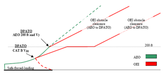
(1) Comparison of obstacle clearance in all performance classes
Figure 1 shows the profiles of the three performance classes — superimposed on one diagram.
— Performance class 1 (PC1): from TDP, requires OEI obstacle clearance in all phases of flight; the construction of Category A procedures, provides for a flight path to the first climb segment, a level acceleration segment to Vy (which may be shown concurrent with the first segment), followed by the second climb segment from Vy at 200 ft (see Figure 1).
Figure 1
All Performance Classes (a comparison)
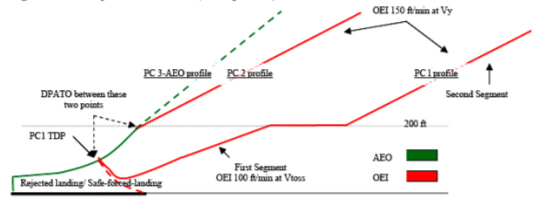
— Performance class 2 (PC2): requires AEO obstacle clearance to DPATO and OEI from then on. The take-off mass has the PC1 second segment climb performance at its basis therefore, at the point where Vy at 200 ft is reached, Performance Class 1 is achieved (see also Figure 3).
— Performance class 3 (PC3): requires AEO obstacle clearance in all phases.
Figure 2
Performance Class 1 distances
(2) Comparison of the discontinued take-off in all performance classes
(i) PC1 — requires a prepared surface on which a rejected landing can be undertaken (no damage); and
(ii) PC2 and 3 — require a safe forced landing surface (some damage can be tolerated, but there must be a reasonable expectancy of no injuries to persons in the aircraft or third parties on the surface).
(d) The derivation of performance class 2
PC2 is primarily based on the text of ICAO Annex 6 Part III Section II and its attachments which provide for the following:
(1) obstacle clearance before DPATO: the helicopter shall be able, with all engines operating, to clear all obstacles by an adequate margin until it is in a position to comply with (2);
(2) obstacle clearance after DPATO: the helicopter shall be able, in the event of the critical engine becoming inoperative at any time after reaching DPATO, to continue the take-off clearing all obstacles along the flight path by an adequate margin until it is able to comply with en-route clearances; and
(3) engine failure before DPATO: before the DPATO, failure of the critical engine may cause the helicopter to force land; therefore, a safe forced landing should be possible (this is analogous to the requirement for a reject in performance class 1, but where some damage to the helicopter can be tolerated.)
(e) Benefits of performance class 2
Operations in performance class 2 permit advantage to be taken of an AEO procedure for a short period during take-off and landing — whilst retaining engine failure accountability in the climb, descent and cruise. The benefits include the ability to:
(1) use (the reduced) distances scheduled for the AEO — thus permitting operations to take place at smaller aerodromes and allowing airspace requirements to be reduced;
(2) operate when the safe forced landing distance available is located outside the boundary of the aerodrome;
(3) operate when the take-off distance required is located outside the boundary of the aerodrome; and
(4) use existing Category A profiles and distances when the surface conditions are not adequate for a reject, but are suitable for a safe forced landing (for example, when the ground is waterlogged).
Additionally, following a risk assessment when the use of exposure is approved by the competent authority the ability to:
(i) operate when a safe forced landing is not assured in the take-off phase; and
(ii) penetrate the HV curve for short periods during take-off or landing.
(f) Implementation of performance class 2 in Part-CAT
The following sections explain the principles of the implementation of performance class 2.
(1) Does ICAO spell it all out?
ICAO Annex 6 does not give guidance on how DPATO should be calculated nor does it require that distances be established for the take-off. However, it does require that, up to DPATO AEO, and from DPATO OEI, obstacle clearance is established (see Figure 3 and Figure 4 which are simplified versions of the diagrams contained in Annex 6 Part III, Attachment A).
(ICAO Annex 8 – Airworthiness of Aircraft (IVA 2.2.3.1.4’ and ‘IVB 2.2.7 d) requires that an AEO distance be scheduled for all helicopters operating in performance classes 2 & 3. ICAO Annex 6 is dependent upon the scheduling of the AEO distances, required in Annex 8, to provide data for the location of DPATO.)
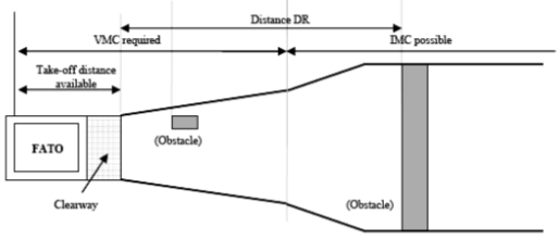
When showing obstacle clearance, the divergent obstacle clearance height required for IFR is — as in performance class 1 — achieved by the application of the additional obstacle clearance of 0.01 distance DR (the distance from the end of ‘take-off-distance-available’ — see the pictorial representation in Figure 4 and the definition in Annex I).
As can also be seen from Figure 4, flight must be conducted in VFR until DPATO has been achieved (and deduced that if an engine failure occurs before DPATO, entry into IFR is not permitted (as the OEI climb gradient will not have been established)).
Figure 3
Performance Class 2 Obstacle Clearance
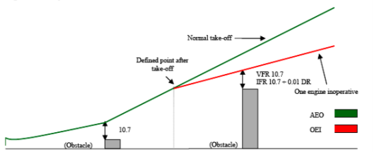
Figure 4
Performance Class 2 Obstacle Clearance (plan view)
(2) Function of DPATO
From the preceding paragraphs, it can be seen that DPATO is germane to PC2. It can also be seen that, in view of the many aspects of DPATO, it has, potentially, to satisfy a number of requirements that are not necessarily synchronised (nor need to be).
It is clear that it is only possible to establish a single point for DPATO, satisfying the requirement of (d)(2) & (d)(3), when:
— accepting the TDP of a Category A procedure; or
— extending the safe forced landing requirement beyond required distances (if data are available to permit the calculation of the distance for a safe forced landing from the DPATO).
It could be argued that the essential requirement for DPATO is contained in section (d)(2) — OEI obstacle clearance. From careful examination of the flight path reproduced in Figure 3 above, it may be reasonably deduced that DPATO is the point at which adequate climb performance is established (examination of Category A procedures would indicate that this could be (in terms of mass, speed and height above the take-off surface) the conditions at the start of the first or second segments — or any point between.)
(The diagrams in Attachment A of ICAO Annex 6 do not appear to take account of drop down — permitted under Category A procedures; similarly with helideck departures, the potential for acceleration in drop down below deck level (once the deck edge has been cleared) is also not shown. These omissions could be regarded as a simplification of the diagram, as drop down is discussed and accepted in the accompanying ICAO text.)
It may reasonably be argued that, during the take-off and before reaching an appropriate climb speed (VTOSS or Vy), Vstayup will already have been achieved (where Vstayup is the ability to continue the flight and accelerate without descent — shown in some Category A procedures as VT or target speed) and where, in the event of an engine failure, no landing would be required.
It is postulated that, to practically satisfy all the requirements of (d)(1), (2) and (3), DPATO does not need to be defined at one synchronised point; provisions can be met separately, i.e. defining the distance for a safe forced landing, and then establishing the OEI obstacle clearance flight path.
As the point at which the helicopter’s ability to continue the flight safely, with the critical engine inoperative is the critical element, it is that for which DPATO is used in this text.
Figure 5
The three elements in a PC 2 take-off
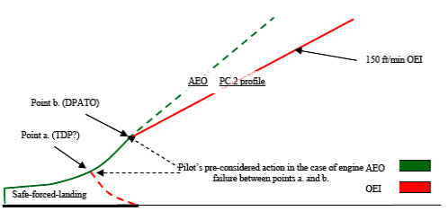
(i) The three elements from the pilot’s perspective
When seen from the pilot’s perspective (see Figure 5), there are three elements of the PC 2 take-off — each with associated related actions which need to be considered in the case of an engine failure:
(A) action in the event of an engine failure — up to the point where a forced-landing will be required;
(B) action in the event of an engine failure — from the point where OEI obstacle clearance is established (DPATO); and
(C) pre-considered action in the event of an engine failure — in the period between (A) and (B)
The action of the pilot in (A) and (B) is deterministic, i.e. it remains the same for every occasion. For pre-consideration of the action at point (C), as is likely that the planned flight path will have to be abandoned (the point at which obstacle clearance using the OEI climb gradients not yet being reached), the pilot must (before take-off) have considered his/her options and the associated risks, and have in mind the course of action that will be pursued in the event of an engine failure during that short period. (As it is likely that any action will involve turning manoeuvres, the effect of turns on performance must be considered.)
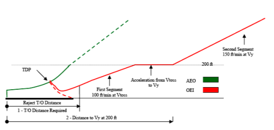
(3) Take-off mass for performance class 2
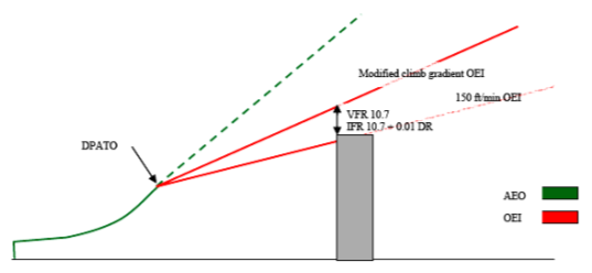
As previously stated, performance class 2 is an AEO take-off that, from DPATO, has to meet the requirement for OEI obstacle clearance in the climb and en-route phases. Take-off mass is, therefore, the mass that gives at least the minimum climb performance of 150 ft/min at Vy, at 1 000 ft above the take-off point, and obstacle clearance.
As can be seen in Figure 6 below, the take-off mass may have to be modified when it does not provide the required OEI clearance from obstacles in the take-off-flight path (exactly as in performance class 1). This could occur when taking off from an aerodrome/operating site where the flight path has to clear an obstacle such a ridge line (or line of buildings) that can neither be:
(i) flown around using VFR and see and avoid; nor
(ii) cleared using the minimum climb gradient given by the take-off mass (150 ft/min at 1 000 ft).
In this case, the take-off mass has to be modified (using data contained in the AFM) to give an appropriate climb gradient.
Figure 6
Performance Class 2 (enhanced climb gradient)
(4) Do distances have to be calculated?
Distances do not have to be calculated if, by using pilot judgement or standard practice, it can be established that:
(i) a safe forced landing is possible following an engine failure (notwithstanding that there might be obstacles in the take-off path); and
(ii) obstacles can be cleared (or avoided) — AEO in the take-off phase and OEI in the climb.
If early entry (in the sense of cloud base) into IMC is expected, an IFR departure should be planned. However, standard masses and departures can be used when described in the operations manual.
(5) The use of Category A data
In Category A procedures, TDP is the point at which either a rejected landing or a safe continuation of the flight, with OEI obstacle clearance, can be performed.
For PC2 (when using Category A data), only the safe forced landing (reject) distance depends on the equivalent of the TDP; if an engine fails between TDP and DPATO, the pilot has to decide what action is required. It is not necessary for a safe forced landing distance to be established from beyond the equivalent of TDP (see Figure 5 and discussion in (f)(2)(ii)(A)).
Category A procedures based on a fixed VTOSS are usually optimised either for the reduction of the rejected take-off distance, or the take-off distance. Category A procedures based on a variable VTOSS allow either a reduction in required distances (low VTOSS) or an improvement in OEI climb capability (high VTOSS). These optimisations may be beneficial in PC2 to satisfy the dimensions of the take-off site.
In view of the different requirements for PC2 (from PC1), it is perfectly acceptable for the two calculations (one to establish the safe forced landing distance and the other to establish DPATO) to be based upon different Category A procedures. However, if this method is used, the mass resulting from the calculation cannot be more than the mass from the more limiting of the procedures.
(6) DPATO and obstacle clearance
If it is necessary for OEI obstacle clearance to be established in the climb, the starting point (DPATO) for the (obstacle clearance) gradient has to be established. Once DPATO is defined, the OEI obstacle clearance is relatively easy to calculate with data from the AFM.
(i) DPATO based on AEO distance
In the simplest case; if provided, the scheduled AEO to 200 ft at Vy can be used (see Figure 7).
Figure 7
Suggested AEO locations for DPATO
Otherwise, and if scheduled in the AFM, the AEO distance to 50 ft (V50) — determined in accordance with CS/JAR 29.63 — can be used (see Figure 7). Where this distance is used, it will be necessary to ensure that the V50 climb out speed is associated with a speed and mass for which OEI climb data are available so that, from V50, the OEI flight path can be constructed.
(ii) DPATO based on Category A distances
It is not necessary for specific AEO distances to be used (although for obvious reasons it is preferable); if they are not available, a flight path (with OEI obstacle clearance) can be established using Category A distances (see Figure 8 and Figure 9) — which will then be conservative.
Figure 8
Using Cat A data; actual and apparent position of DPATO (Vtoss and start of first segment)
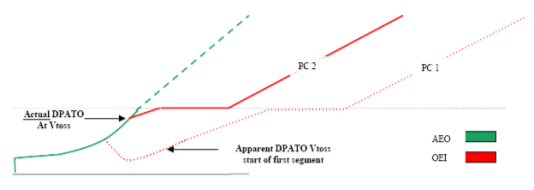
The apparent DPATO is for planning purposes only in the case where AEO data are not available to construct the take-off flight path. The actual OEI flight path will provide better obstacle clearance than the apparent one (used to demonstrate the minimum requirement) — as seen from the firm and dashed lines in the above figure.
Figure 9
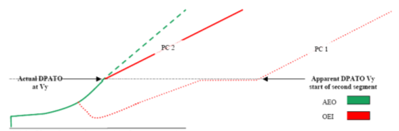
Using Cat A data; actual and apparent position of DPATO (Vy and start of second segment)
(iii) Use of most favourable Category A data
The use of AEO data are recommended for calculating DPATO. However, where an AEO distance is not provided in the flight manual, distance to Vy at 200 ft, from the most favourable of the Category A procedures, can be used to construct a flight path (provided it can be demonstrated that AEO distance to 200 ft at Vy is always closer to the take-off point than the CAT A OEI flight path).
In order to satisfy the requirement of CAT.POL.H.315, the last point from where the start of OEI obstacle clearance can be shown is at 200 ft.
(7) The calculation of DPATO — a summary
DPATO should be defined in terms of speed and height above the take-off surface and should be selected such that AFM data (or equivalent data) are available to establish the distance from the start of the take-off up to the DPATO (conservatively if necessary).
(i) First method
DPATO is selected as the AFM Category B take-off distance (V50 speed or any other take-off distance scheduled in accordance with CS/JAR 29.63) provided that within the distance the helicopter can achieve:
(A) one of the VTOSS values (or the unique VTOSS value if it is not variable) provided in the AFM, selected so as to assure a climb capability according to Category A criteria; or
(B) Vy.
Compliance with CAT.POL.H.315 would be shown from V50 (or the scheduled Category B take-off distance).
(ii) Second method
DPATO is selected as equivalent to the TDP of a Category A ‘clear area’ take-off procedure conducted in the same conditions.
Compliance with CAT.POL.H.315 would be shown from the point at which VTOSS, a height of at least 35 ft above the take-off surface and a positive climb gradient are achieved (which is the Category A ‘clear area’ take-off distance).
Safe forced landing areas should be available from the start of the take-off, to a distance equal to the Category A ‘clear area’ rejected take-off distance.
(iii) Third method
As an alternative, DPATO could be selected such that AFM OEI data are available to establish a flight path initiated with a climb at that speed. This speed should then be:
(A) one of the VTOSS values (or the unique VTOSS value if it is not variable) provided in the AFM, selected so as to assure a climb capability according to Category A criteria; or
(B) Vy
The height of the DPATO should be at least 35 ft and can be selected up to 200 ft. Compliance with CAT.POL.H.315 would be shown from the selected height.
(8) Safe forced landing distance
Except as provided in (f)(7)(ii), the establishment of the safe forced landing distance could be problematical as it is not likely that PC2 specific data will be available in the AFM.
By definition, the Category A reject distance may be used when the surface is not suitable for a reject, but may be satisfactory for a safe forced landing (for example, where the surface is flooded or is covered with vegetation).
Any Category A (or other accepted) data may be used to establish the distance. However, once established, it remains valid only if the Category A mass (or the mass from the accepted data) is used and the Category A (or accepted) AEO profile to the TDP is flown. In view of these constraints, the likeliest Category A procedures are the clear area or the short field (restricted area/site) procedures.
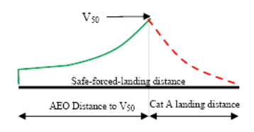
From Figure 10, it can be seen that if the Category B V50 procedure is used to establish DPATO, the combination of the distance to 50 ft and the Category A ‘clear area’ landing distance, required by CS/JAR 29.81 (the horizontal distance required to land and come to a complete stop from a point 50 ft above the landing surface), will give a good indication of the maximum safe-forced-landing distance required (see also the explanation on Vstayup above).
Figure 10
Category B (V50) safe–forced–landing distance
(9) Performance class 2 landing
For other than PC2 operations to elevated FATOs or helidecks (see section (g)(4)(i)), the principles for the landing case are much simpler. As the performance requirements for PC1 and PC2 landings are virtually identical, the condition of the landing surface is the main issue.
If the engine fails at any time during the approach, the helicopter must be able either: to perform a go-around meeting the requirements of CAT.POL.H.315; or perform a safe forced landing on the surface. In view of this, and if using PC1 data, the LDP should not be lower that the corresponding TDP (particularly in the case of a variable TDP).
The landing mass will be identical to the take-off mass for the same site (with consideration for any reduction due to obstacle clearance — as shown in Figure 6 above).
In the case of a balked landing (i.e. the landing site becomes blocked or unavailable during the approach), the full requirement for take-off obstacle clearance must be met.
(g) Operations in performance class 2 with exposure
The Implementing Rules offer an opportunity to discount the requirement for an assured safe forced landing area in the take-off or landing phase — subject to an approval from the competent authority. The following sections deals with this option:
(1) Limit of exposure
As stated above, performance class 2 has to ensure AEO obstacle clearance to DPATO and OEI obstacle clearance from that point. This does not change with the application of exposure.
It can, therefore, be stated that operations with exposure are concerned only with alleviation from the requirement for the provision of a safe forced landing.
The absolute limit of exposure is 200 ft — from which point OEI obstacle clearance must be shown.
(2) The principle of risk assessment
ICAO Annex 6 Part III Chapter 3.1.2 states that:
‘3.1.2 In conditions where the safe continuation of flight is not ensured in the event of a critical engine failure, helicopter operations shall be conducted in a manner that gives appropriate consideration for achieving a safe forced landing.’
Although a safe forced landing may no longer be the (absolute) Standard, it is considered that risk assessment is obligatory to satisfy the amended requirement for ‘appropriate consideration’.
Risk assessment used for fulfilment of this proposed Standard is consistent with principles described in ‘AS/NZS 4360:1999’. Terms used in this text and defined in the AS/NZS Standard are shown in Sentence Case e.g. risk assessment or risk reduction.
(3) The application of risk assessment to performance class 2
Under circumstances where no risk attributable to engine failure (beyond that inherent in the safe forced landing) is present, operations in performance class 2 may be conducted in accordance with the non-alleviated requirements contained above — and a safe forced landing will be possible.
Under circumstances where such risk would be present, i.e. operations to an elevated FATO (deck edge strike); or, when permitted, operations from a site where a safe forced landing cannot be accomplished because the surface is inadequate; or where there is penetration into the HV curve for a short period during take-off or landing (a limitation in CS/JAR 29 AFMs), operations have to be conducted under a specific approval.
Provided such operations are risk assessed and can be conducted to an established safety target, they may be approved in accordance with CAT.POL.H.305.
(i) The elements of the risk management
The approval process consists of an operational risk assessment and the application of four principles:
(A) a safety target;
(B) a helicopter reliability assessment;
(C) continuing airworthiness; and
(D) mitigating procedures.
(ii) The safety target
The main element of the risk assessment when exposure was initially introduced by the JAA into JAR-OPS 3 (NPA OPS-8), was the assumption that turbine engines in helicopters would have failure rates of about 1:100 000 per flying hour, which would permit (against the agreed safety target of 5 x 10⁻⁸ per event) an exposure of about 9 seconds for twins during the take-off or landing event. (When choosing this target it was assumed that the majority of current well-maintained turbine powered helicopters would be capable of meeting the event target — it, therefore, represents the residual risk).
(Residual risk is considered to be the risk that remains when all mitigating procedures — airworthiness and operational — are applied (see sections (g)(3)(iv) and (g)(3)(v))).
(iii) The reliability assessment
The reliability assessment was initiated to test the hypothesis (stated in (g)(3)(ii) ) that the majority of turbine powered types would be able to meet the safety target. This hypothesis could only be confirmed by an examination of the manufacturers’ power-loss data.
(iv) Mitigating procedures (airworthiness)
Mitigating procedures consist of a number of elements:
(A) the fulfilment of all manufacturers’ safety modifications;
(B) a comprehensive reporting system (both failures and usage data); and
(C) the implementation of a usage monitoring system (UMS).
Each of these elements is to ensure that engines, once shown to be sufficiently reliable to meet the safety target, will sustain such reliability (or improve upon it).
The monitoring system is felt to be particularly important as it had already been demonstrated that when such systems are in place it inculcates a more considered approach to operations. In addition, the elimination of ‘hot starts’, prevented by the UMS, itself minimises the incidents of turbine burst failures.
(v) Mitigating procedures (operations)
Operational and training procedures, to mitigate the risk — or minimise the consequences — are required of the operator. Such procedures are intended to minimise risk by ensuring that:
(A) the helicopter is operated within the exposed region for the minimum time; and
(B) simple but effective procedures are followed to minimise the consequence should an engine failure occur.
(4) Operation with exposure
When operating with exposure, there is alleviation from the requirement to establish a safe forced landing area (which extends to landing as well as take-off). However, the requirement for obstacle clearance — AEO in the take-off and from DPATO OEI in the climb and en-route phases — remains (both for take-off and landing).
The take-off mass is obtained from the more limiting of the following:
— the climb performance of 150 ft/min at 1 000 ft above the take-off point; or
— obstacle clearance (in accordance with (f)(3) above); or
— AEO hover out of ground effect (HOGE) performance at the appropriate power setting. (AEO HOGE is required to ensure acceleration when (near) vertical dynamic take-off techniques are being used. Additionally, for elevated FATO or helidecks, it ensures a power reserve to offset ground cushion dissipation; and ensures that, during the landing manoeuvre, a stabilised HOGE is available — should it be required.)
(i) Operations to elevated FATOs or helidecks
PC2 operations to elevated FATOs and helidecks are a specific case of operations with exposure. In these operations, the alleviation covers the possibility of:
(A) a deck-edge strike if the engine fails early in the take-off or late in the landing;
(B) penetration into the HV Curve during take-off and landing; and
(C) forced landing with obstacles on the surface (hostile water conditions) below the elevated FATO (helideck). The take-of mass is as stated above and relevant techniques are as described in GM1 CAT.POL.H.310(c) & CAT.POL.H.325(c).
It is unlikely that the DPATO will have to be calculated with operations to helidecks (due to the absence of obstacles in the take-off path).
(ii) Additional requirements for operations to helidecks in a hostile environment
For a number of reasons (e.g. the deck size, and the helideck environment — including obstacles and wind vectors), it was not anticipated that operations in PC1 would be technically feasible or economically justifiable by the projected JAA deadline of 2010 (OEI HOGE could have provided a method of compliance, but this would have resulted in a severe and unwarranted restriction on payload/range).
However, due to the severe consequences of an engine failure to helicopters involved in take-off and landings to helidecks located in hostile sea areas (such as the North Sea or the North Atlantic), a policy of risk reduction is called for. As a result, enhanced class 2 take-off and landing masses together with techniques that provide a high confidence of safety due to:
(A) deck-edge avoidance; and
(B) drop-down that provides continued flight clear of the sea,
are seen as practical measures.
For helicopters which have a Category A elevated helideck procedure, certification is satisfied by demonstrating a procedure and adjusted masses (adjusted for wind as well as temperature and pressure) that assure a 15-ft deck edge clearance on take-off and landing. It is, therefore, recommended that manufacturers, when providing enhanced PC2 procedures, use the provision of this deck-edge clearance as their benchmark.
As the height of the helideck above the sea is a variable, drop down has to be calculated; once clear of the helideck, a helicopter operating in PC1 would be expected to meet the 35-ft obstacle clearance. Under circumstances other than open sea areas and with less complex environmental conditions, this would not present difficulties. As the provision of drop down takes no account of operational circumstances, standard drop down graphs for enhanced PC2 — similar to those in existence for Category A procedures — are anticipated.
Under conditions of offshore operations, calculation of drop down is not a trivial matter — the following examples indicate some of the problems which might be encountered in hostile environments:
(A) Occasions when tide is not taken into account and the sea is running irregularly — the level of the obstacle (i.e. the sea) is indefinable making a true calculation of drop down impossible.
(B) Occasions when it would not be possible — for operational reasons — for the approach and departure paths to be clear of obstacles — the ‘standard’ calculation of drop-down could not be applied.
Under these circumstances, practicality indicates that drop down should be based upon the height of the deck AMSL and the 35-ft clearance should be applied.
There are, however, other and more complex issues which will also affect the deck-edge clearance and drop down calculations.
(C) When operating to moving decks on vessels, a recommended landing or take-off profile might not be possible because the helicopter might have to hover alongside in order that the rise and fall of the ship is mentally mapped; or, on take-off re-landing in the case of an engine failure might not be an option.
Under these circumstances, the commander might adjust the profiles to address a hazard more serious or more likely than that presented by an engine failure.
It is because of these and other (unforeseen) circumstances that a prescriptive requirement is not used. However, the target remains a 15-ft deck-edge clearance and a 35-ft obstacle clearance and data should be provided such that, where practically possible, these clearances can be planned.
As accident/incident history indicates that the main hazard is collision with obstacles on the helideck due to human error, simple and reproducible take-off and landing procedures are recommended.
In view of the reasons stated above, the future requirement for PC1 was replaced by the new requirement that the take-off mass takes into account:
— the procedure;
— deck-edge miss; and
— drop down appropriate to the height of the helideck.
This will require calculation of take-off mass from information produced by manufacturers reflecting these elements. It is expected that such information will be produced by performance modelling/simulation using a model validated through limited flight testing.
(iii) Operations to helidecks for helicopters with a maximum operational passenger seating configuration (MOPSC) of more than 19
The original requirement for operations of helicopters with an MOPSC of more than 19 was PC1 (as set out in CAT.POL.H.100(b)(2)).
However, when operating to helidecks, the problems enumerated in (g)(4)(ii) above are equally applicable to these helicopters. In view of this, but taking into account that increased numbers are (potentially) being carried, such operations are permitted in PC2 (CAT.POL.H.100(b)(2)) but, in all helideck environments (both hostile and non-hostile), have to satisfy, the additional requirements, set out in (g)(4)(ii) above.
CAT.POL.H.305 Operations without an assured safe forced landing capability
Regulation (EU) No 965/2012
(a) Operations without an assured safe forced landing capability during the take-off and landing phases shall only be conducted if the operator has been granted an approval by the competent authority.
(b) To obtain and maintain such approval the operator shall:
(1) conduct a risk assessment, specifying:
(i) the type of helicopter; and
(ii) the type of operations;
(2) implement the following set of conditions:
(i) attain and maintain the helicopter/engine modification standard defined by the manufacturer;
(ii) conduct the preventive maintenance actions recommended by the helicopter or engine manufacturer;
(iii) include take-off and landing procedures in the operations manual, where they do not already exist in the AFM;
(iv) specify training for flight crew; and
(v) provide a system for reporting to the manufacturer loss of power, engine shutdown or engine failure events;
and
(3) implement a usage monitoring system (UMS).
VALIDITY OF THE RISK ASSESSMENT
The operator should periodically review and update the procedures and associated risk assessments, pertaining to the granting of the CAT.POL.H.305(a) approval, to ensure that they are adequate and remain relevant for the operation.
ENGINE RELIABILITY STATISTICS
(a) As part of the risk assessment prior to granting an approval under CAT.POL.H.305, the operator should provide appropriate engine reliability statistics available for the helicopter type and the engine type.
(b) Except in the case of new engines, such data should show sudden power loss from the set of in-flight shutdown (IFSD) events not exceeding 1 per 100 000 engine hours in a 5 year moving window. However, a rate in excess of this value, but not exceeding 3 per 100 000 engine hours, may be accepted by the competent authority after an assessment showing an improving trend.
(c) New engines should be assessed on a case-by-case basis.
(d) After the initial assessment, updated statistics should be periodically reassessed; any adverse sustained trend will require an immediate evaluation to be accomplished by the operator in consultation with the competent authority and the manufacturers concerned. The evaluation may result in corrective action or operational restrictions being applied.
(e) The purpose of this paragraph is to provide guidance on how the in-service power plant sudden power loss rate is determined.
(1) Share of roles between the helicopter and engine type certificate holders (TCH)
(i) The provision of documents establishing the in-service sudden power loss rate for the helicopter/engine installation; the interface with the operational authority of the State of the operator should be the engine TCH or the helicopter TCH depending on the way they share the corresponding analysis work.
(ii) The engine TCH should provide the helicopter TCH with a document including: the list of in-service power loss events, the applicability factor for each event (if used), and the assumptions made on the efficiency of any corrective actions implemented (if used).
(iii) The engine or helicopter TCH should provide the operational authority of the State of the operator, with a document that details the calculation results taking into account the following:
(A) events caused by the engine and the events caused by the engine installation;
(B) applicability factor for each event (if used), the assumptions made on the efficiency of any corrective actions implemented on the engine and on the helicopter (if used); and
(C) calculation of the power plant power loss rate.
(2) Documentation
The following documentation should be updated every year:
(i) the document with detailed methodology and calculation as distributed to the authority of the State of design;
(ii) a summary document with results of computation as made available on request to any operational authority; and
(iii) a service letter establishing the eligibility for such operation and defining the corresponding required configuration as provided to the operators.
(3) Definition of ‘sudden in-service power loss’
Sudden in-service power loss is an engine power loss:
(i) larger than 30 % of the take-off power;
(ii) occurring during operation; and
(iii) without the occurrence of an early intelligible warning to inform and give sufficient time for the pilot to take any appropriate action.
(4) Database documentation
Each power loss event should be documented, by the engine and/or helicopter TCHs, as follows:
(i) incident report number;
(ii) engine type;
(iii) engine serial number;
(iv) helicopter serial number;
(v) date;
(vi) event type (demanded IFSD, un-demanded IFSD);
(vii) presumed cause;
(viii) applicability factor when used; and
(ix) reference and assumed efficiency of the corrective actions that will have to be applied (if any).
(5) Counting methodology
Various methodologies for counting engine power loss rate have been accepted by authorities. The following is an example of one of these methodologies.
(i) The events resulting from:
(A) unknown causes (wreckage not found or totally destroyed, undocumented or unproven statements);
(B) where the engine or the elements of the engine installation have not been investigated (for example, when the engine has not been returned by the customer); or
(C) an unsuitable or non-representative use (operation or maintenance) of the helicopter or the engine,
are not counted as engine in-service sudden power loss and the applicability factor is 0 %.
(ii) The events caused by:
(A) the engine or the engine installation; or
(B) the engine or helicopter maintenance, when the applied maintenance was compliant with the maintenance manuals,
are counted as engine in-service sudden power loss and the applicability factor is 100 %.
(iii) For the events where the engine or an element of the engine installation has been submitted for investigation, but where this investigation subsequently failed to define a presumed cause, the applicability factor is 50 %.
(6) Efficiency of corrective actions
The corrective actions made by the engine and helicopter manufacturers on the definition or maintenance of the engine or its installation may be defined as mandatory for specific operations. In this case, the associated reliability improvement may be considered as a mitigating factor for the event.
A factor defining the efficiency of the corrective action may be applied to the applicability factor of the concerned event.
(7) Method of calculation of the power plant power loss rate
The detailed method of calculation of the power plant power loss rate should be documented by engine or helicopter TCH and accepted by the relevant authority.
IMPLEMENTATION OF THE SET OF CONDITIONS
To obtain an approval under CAT.POL.H.305(a), the operator conducting operations without an assured safe forced landing capability should implement the following:
(a) Attain and then maintain the helicopter/engine modification standard defined by the manufacturer that has been designated to enhance reliability during the take-off and landing phases.
(b) Conduct the preventive maintenance actions recommended by the helicopter or engine manufacturer as follows:
(1) engine oil spectrometric and debris analysis — as appropriate;
(2) engine trend monitoring, based on available power assurance checks;
(3) engine vibration analysis (plus any other vibration monitoring systems where fitted); and
(4) oil consumption monitoring.
(c) The usage monitoring system should fulfil at least the following:
(1) Recording of the following data:
(i) date and time of recording, or a reliable means of establishing these parameters;
(ii) amount of flight hours recorded during the day plus total flight time;
(iii) N1 (gas producer RPM) cycle count;
(iv) N2 (power turbine RPM) cycle count (if the engine features a free turbine);
(v) turbine temperature exceedance: value, duration;
(vi) power-shaft torque exceedance: value, duration (if a torque sensor is fitted);
(vii) engine shafts speed exceedance: value, duration.
(2) Data storage of the above parameters, if applicable, covering the maximum flight time in a day, and not less than 5 flight hours, with an appropriate sampling interval for each parameter.
(3) The system should include a comprehensive self-test function with a malfunction indicator and a detection of power-off or sensor input disconnection.
(4) A means should be available for downloading and analysis of the recorded parameters. Frequency of downloading should be sufficient to ensure data are not lost through overwriting.
(5) The analysis of parameters gathered by the usage monitoring system, the frequency of such analysis and subsequent maintenance actions should be described in the maintenance documentation.
(6) The data should be stored in an acceptable form and accessible to the competent authority for at least 24 months.
(d) The training for flight crew should include the discussion, demonstration, use and practice of the techniques necessary to minimise the risks.
(e) Report to the manufacturer any loss of power control, engine shutdown (precautionary or otherwise) or engine failure for any cause (excluding simulation of engine failure during training). The content of each report should provide:
(1) date and time;
(2) operator (and maintenance organisations where relevant);
(3) type of helicopter and description of operations;
(4) registration and serial number of airframe;
(5) engine type and serial number;
(6) power unit modification standard where relevant to failure;
(7) engine position;
(8) symptoms leading up to the event;
(9) circumstances of engine failure including phase of flight or ground operation;
(10) consequences of the event;
(11) weather/environmental conditions;
(12) reason for engine failure — if known;
(13) in case of an in-flight shutdown (IFSD), nature of the IFSD (demanded/un-demanded);
(14) procedure applied and any comment regarding engine restart potential;
(15) engine hours and cycles (from new and last overhaul);
(16) airframe flight hours;
(17) rectification actions applied including, if any, component changes with part number and serial number of the removed equipment; and
(18) any other relevant information.
USE OF FULL AUTHORITY DIGITAL ENGINE CONTROL (FADEC)
Current technology increasingly allows for the recording function required in (c)(1) of AMC2 CAT.POL.H.305(b) to be incorporated in the full authority digital engine control (FADEC).
Where a FADEC is capable of recording some of the parameters required by (c)(1) of AMC2 CAT.POL.H.305(b), it is not intended that the recording of the parameters is to be duplicated.
Providing that the functions as set out in (c) of AMC2 CAT.POL.H.305(b) are satisfied, the FADEC may partially, or in whole, fulfil the requirement for recording and storing parameters in a usage monitoring system.
Regulation (EU) No 965/2012
(a) The take-off mass shall not exceed the maximum mass specified for a rate of climb of 150 ft/min at 300 m (1 000 ft) above the level of the aerodrome or operating site with the critical engine inoperative and the remaining engine(s) operating at an appropriate power rating.
(b) For operations other than those specified in CAT.POL.H.305, the take-off shall be conducted such that a safe forced landing can be executed until the point where safe continuation of the flight is possible.
(c) For operations in accordance with CAT.POL.H.305, in addition to the requirements of (a):
(1) the take-off mass shall not exceed the maximum mass specified in the AFM for an all engines operative out of ground effect (AEO OGE) hover in still air with all engines operating at an appropriate power rating; or
(2) for operations from a helideck:
(i) with a helicopter that has an MOPSC of more than 19; or
(ii) any helicopter operated from a helideck located in a hostile environment,
the take-off mass shall take into account: the procedure; deck-edge miss and drop down appropriate to the height of the helideck with the critical engine(s) inoperative and the remaining engines operating at an appropriate power rating.
(d) When showing compliance with (a) to (c), account shall be taken of the appropriate parameters of CAT.POL.H.105(c) at the point of departure.
(e) That part of the take-off before the requirement of CAT.POL.H.315 is met shall be conducted in sight of the surface.
TAKE-OFF AND LANDING TECHNIQUES
(a) This GM describes three types of operation to/from helidecks and elevated FATOs by helicopters operating in performance class 2.
(b) In two cases of take-off and landing, exposure time is used. During the exposure time (which is only approved for use when complying with CAT.POL.H.305), the probability of an engine failure is regarded as extremely remote. If an engine failure occurs during the exposure time, a safe forced landing may not be possible.
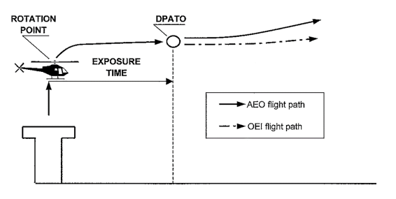
(c) Take-off — non-hostile environment (without an approval to operate with an exposure time) CAT.POL.H.310(b).
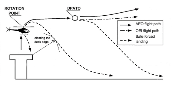
(1) Figure 1 shows a typical take-off profile for performance class 2 operations from a helideck or an elevated FATO in a non-hostile environment.
(2) If an engine failure occurs during the climb to the rotation point, compliance with CAT.POL.H.310(b) will enable a safe landing or a safe forced landing on the deck.
(3) If an engine failure occurs between the rotation point and the DPATO, compliance with CAT.POL.H.310(b) will enable a safe forced landing on the surface, clearing the deck edge.
(4) At or after the DPATO, the OEI flight path should clear all obstacles by the margins specified in CAT.POL.H.315.
Figure 1
Typical take-off profile PC2 from a helideck/elevated FATO, non-hostile environment
(d) Take-off — non-hostile environment (with exposure time) CAT.POL.H.310(c)
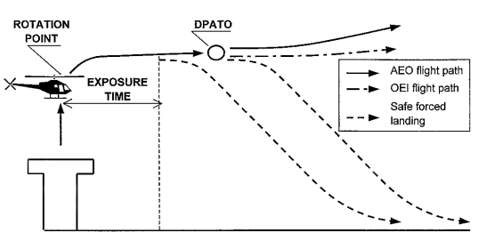
(1) Figure 2 shows a typical take-off profile for performance class 2 operations from a helideck or an elevated FATO in a non-hostile environment (with exposure time).
(2) If an engine failure occurs after the exposure time and before DPATO, compliance with CAT.POL.H.310(c) will enable a safe forced landing on the surface.
(3) At or after the DPATO, the OEI flight path should clear all obstacles by the margins specified in CAT.POL.H.315.
Figure 2
Typical take-off profile PC2 from a helideck/elevated FATO with exposure time, non-hostile environment
(e) Take-off — non-congested hostile environment (with exposure time) CAT.POL.H.310(c)
(1) Figure 3 shows a typical take off profile for performance class 2 operations from a helideck or an elevated FATO in a non-congested hostile environment (with exposure time).
(2) If an engine failure occurs after the exposure time, the helicopter is capable of a safe forced landing or safe continuation of the flight.
(3) At or after the DPATO, the OEI flight path should clear all obstacles by the margins specified in CAT.POL.H.315.
Figure 3
Typical take-off profile PC2 from a helideck/elevated FATO, non-congested hostile environment
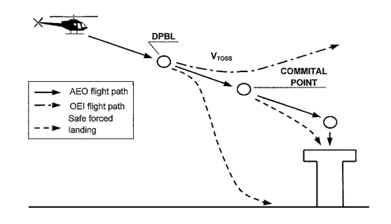
(f) Landing — non-hostile environment (without an approval to operate with an exposure time) CAT.POL.H.325(b)
(1) Figure 4 shows a typical landing profile for performance class 2 operations to a helideck or an elevated FATO in a non-hostile environment.
(2) The DPBL is defined as a ‘window’ in terms of airspeed, rate of descent, and height above the landing surface. If an engine failure occurs before the DPBL, the pilot may elect to land or to execute a balked landing.
(3) In the event of an engine failure being recognised after the DPBL and before the committal point, compliance with CAT.POL.H.325(b) will enable a safe forced landing on the surface.
(4) In the event of an engine failure at or after the committal point, compliance with CAT.POL.H.325(b) will enable a safe forced landing on the deck.
Figure 4
Typical landing profile PC2 to a helideck/elevated FATO, non-hostile environment
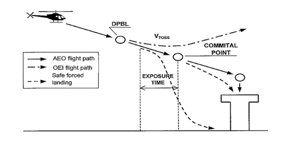
(g) Landing — non-hostile environment (with exposure time) CAT.POL.H.325(c)
(1) Figure 5 shows a typical landing profile for performance class 2 operations to a helideck or an elevated FATO in a non-hostile environment (with exposure time).
(2) The DPBL is defined as a ‘window’ in terms of airspeed, rate of descent, and height above the landing surface. If an engine failure occurs before the DPBL, the pilot may elect to land or to execute a balked landing.
(3) In the event of an engine failure being recognised before the exposure time, compliance with CAT.POL.H.325(c) will enable a safe forced landing on the surface.
(4) In the event of an engine failure after the exposure time, compliance with CAT.POL.H.325(c) will enable a safe forced landing on the deck.
Figure 5
Typical landing profile PC2 to a helideck/elevated FATO with exposure time, non-hostile environment
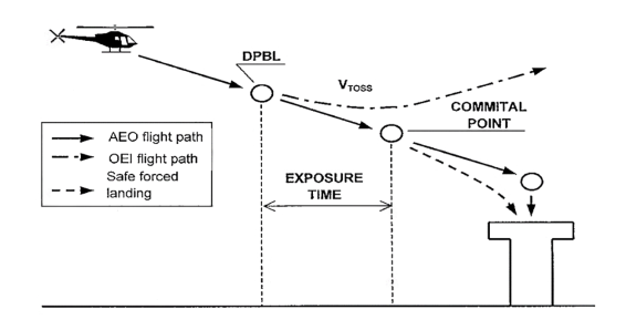
(h) Landing — non-congested hostile environment (with exposure time) CAT.POL.H.325(c)
(1) Figure 6 shows a typical landing profile for performance class 2 operations to a helideck or an elevated FATO in a non-congested hostile environment (with exposure time).
(2) In the event of an engine failure at any point during the approach and landing phase up to the start of exposure time, compliance with CAT.POL.H.325(b) will enable the helicopter, after clearing all obstacles under the flight path, to continue the flight.
(3) In the event of an engine failure after the exposure time (i.e. at or after the committal point), a safe forced landing should be possible on the deck.
Figure 6
Typical landing profile PC2 to a helideck/elevated FATO with exposure time, non-congested hostile environment
Regulation (EU) No 965/2012
(a) The landing mass at the estimated time of landing shall not exceed the maximum mass specified for a rate of climb of 150 ft/min at 300 m (1 000 ft) above the level of the aerodrome or operating site with the critical engine inoperative and the remaining engine(s) operating at an appropriate power rating.
(b) If the critical engine fails at any point in the approach path:
(1) a balked landing can be carried out meeting the requirement of CAT.POL.H.315; or
(2) for operations other than those specified in CAT.POL.H.305, the helicopter can perform a safe forced landing.
(c) For operations in accordance with CAT.POL.H.305, in addition to the requirements of (a):
(1) the landing mass shall not exceed the maximum mass specified in the AFM for an AEO OGE hover in still air with all engines operating at an appropriate power rating; or
(2) for operations to a helideck:
(i) with a helicopter that has an MOPSC of more than 19; or
(ii) any helicopter operated to a helideck located in a hostile environment,
the landing mass shall take into account the procedure and drop down appropriate to the height of the helideck with the critical engine inoperative and the remaining engine(s) operating at an appropriate power rating.
(d) When showing compliance with (a) to (c), account shall be taken of the appropriate parameters of CAT.POL.H.105(c) at the destination aerodrome or any alternate, if required.
(e) That part of the landing after which the requirement of (b)(1) cannot be met shall be conducted in sight of the surface.
TAKE-OFF AND LANDING TECHNIQUES
(a) This GM describes three types of operation to/from helidecks and elevated FATOs by helicopters operating in performance class 2.
(b) In two cases of take-off and landing, exposure time is used. During the exposure time (which is only approved for use when complying with CAT.POL.H.305), the probability of an engine failure is regarded as extremely remote. If an engine failure occurs during the exposure time, a safe forced landing may not be possible.
(c) Take-off — non-hostile environment (without an approval to operate with an exposure time) CAT.POL.H.310(b).
(1) Figure 1 shows a typical take-off profile for performance class 2 operations from a helideck or an elevated FATO in a non-hostile environment.
(2) If an engine failure occurs during the climb to the rotation point, compliance with CAT.POL.H.310(b) will enable a safe landing or a safe forced landing on the deck.
(3) If an engine failure occurs between the rotation point and the DPATO, compliance with CAT.POL.H.310(b) will enable a safe forced landing on the surface, clearing the deck edge.
(4) At or after the DPATO, the OEI flight path should clear all obstacles by the margins specified in CAT.POL.H.315.
Figure 1
Typical take-off profile PC2 from a helideck/elevated FATO, non-hostile environment
(d) Take-off — non-hostile environment (with exposure time) CAT.POL.H.310(c)
(1) Figure 2 shows a typical take-off profile for performance class 2 operations from a helideck or an elevated FATO in a non-hostile environment (with exposure time).
(2) If an engine failure occurs after the exposure time and before DPATO, compliance with CAT.POL.H.310(c) will enable a safe forced landing on the surface.
(3) At or after the DPATO, the OEI flight path should clear all obstacles by the margins specified in CAT.POL.H.315.
Figure 2
Typical take-off profile PC2 from a helideck/elevated FATO with exposure time, non-hostile environment
(e) Take-off — non-congested hostile environment (with exposure time) CAT.POL.H.310(c)
(1) Figure 3 shows a typical take off profile for performance class 2 operations from a helideck or an elevated FATO in a non-congested hostile environment (with exposure time).
(2) If an engine failure occurs after the exposure time, the helicopter is capable of a safe forced landing or safe continuation of the flight.
(3) At or after the DPATO, the OEI flight path should clear all obstacles by the margins specified in CAT.POL.H.315.
Figure 3
Typical take-off profile PC2 from a helideck/elevated FATO, non-congested hostile environment
(f) Landing — non-hostile environment (without an approval to operate with an exposure time) CAT.POL.H.325(b)
(1) Figure 4 shows a typical landing profile for performance class 2 operations to a helideck or an elevated FATO in a non-hostile environment.
(2) The DPBL is defined as a ‘window’ in terms of airspeed, rate of descent, and height above the landing surface. If an engine failure occurs before the DPBL, the pilot may elect to land or to execute a balked landing.
(3) In the event of an engine failure being recognised after the DPBL and before the committal point, compliance with CAT.POL.H.325(b) will enable a safe forced landing on the surface.
(4) In the event of an engine failure at or after the committal point, compliance with CAT.POL.H.325(b) will enable a safe forced landing on the deck.
Figure 4
Typical landing profile PC2 to a helideck/elevated FATO, non-hostile environment
(g) Landing — non-hostile environment (with exposure time) CAT.POL.H.325(c)
(1) Figure 5 shows a typical landing profile for performance class 2 operations to a helideck or an elevated FATO in a non-hostile environment (with exposure time).
(2) The DPBL is defined as a ‘window’ in terms of airspeed, rate of descent, and height above the landing surface. If an engine failure occurs before the DPBL, the pilot may elect to land or to execute a balked landing.
(3) In the event of an engine failure being recognised before the exposure time, compliance with CAT.POL.H.325(c) will enable a safe forced landing on the surface.
(4) In the event of an engine failure after the exposure time, compliance with CAT.POL.H.325(c) will enable a safe forced landing on the deck.
Figure 5
Typical landing profile PC2 to a helideck/elevated FATO with exposure time, non-hostile environment
(h) Landing — non-congested hostile environment (with exposure time) CAT.POL.H.325(c)
(1) Figure 6 shows a typical landing profile for performance class 2 operations to a helideck or an elevated FATO in a non-congested hostile environment (with exposure time).
(2) In the event of an engine failure at any point during the approach and landing phase up to the start of exposure time, compliance with CAT.POL.H.325(b) will enable the helicopter, after clearing all obstacles under the flight path, to continue the flight.
(3) In the event of an engine failure after the exposure time (i.e. at or after the committal point), a safe forced landing should be possible on the deck.
Figure 6
Typical landing profile PC2 to a helideck/elevated FATO with exposure time, non-congested hostile environment
CHAPTER 4 – Performance class 3
Regulation (EU) No 965/2012
(a) Helicopters operated in performance class 3 shall be certified in category A or equivalent as determined by the Agency, or category B.
(b) Operations shall only be conducted in a non-hostile environment, except:
(1)when operating in accordance with CAT.POL.H.420; or
(2) for the take-off and landing phase, when operating in accordance with (c).
(c) Provided the operator is approved in accordance with CAT.POL.H.305, operations may be conducted to/from an aerodrome or operating site located outside a congested hostile environment without an assured safe forced landing capability:
(1) during take-off, before reaching Vy (speed for best rate of climb) or 200 ft above the take-off surface; or
(2) during landing, below 200 ft above the landing surface.
(d) Operations shall not be conducted:
(1) out of sight of the surface;
(2) at night;
(3) when the ceiling is less than 600 ft; or
(4) when the visibility is less than 800 m.
THE TAKE-OFF AND LANDING PHASES (PERFORMANCE CLASS 3)
(a) To understand the use of ground level exposure in performance class 3, it is important first to be aware of the logic behind the use of ‘take-off and landing phases’. Once this is clear, it is easier to appreciate the aspects and limits of the use of ground level exposure. This GM shows the derivation of the term from the ICAO definition of the ‘en-route phase’ and then gives practical examples of the use, and limitations on the use, of ground level exposure in CAT.POL.400(c).
(b) The take-off phase in performance class 1 and performance class 2 may be considered to be bounded by ‘the specified point in the take-off’ from which the take-off flight path begins.
(1) In performance class 1, this specified point is defined as ‘the end of the take-off distance required’.
(2) In performance class 2, this specified point is defined as DPATO or, as an alternative, no later than 200 ft above the take-off surface.
(3) There is no simple equivalent point for bounding of the landing in performance classes 1 & 2.
(c) Take-off flight path is not used in performance class 3 and, consequently, the term ‘take-off and landing phases’ is used to bound the limit of exposure. For the purpose of performance class 3, the take-off and landing phases are as set out in CAT.POL.H.400(c) and are considered to be bounded by:
(1) during take-off before reaching Vy (speed for best rate of climb) or 200 ft above the take-off surface; and
(2) during landing, below 200 ft above the landing surface.
(ICAO Annex 6 Part III, defines en-route phase as being ‘That part of the flight from the end of the take-off and initial climb phase to the commencement of the approach and landing phase.’ The use of take-off and landing phase in this text is used to distinguish the take-off from the initial climb, and the landing from the approach: they are considered to be complementary and not contradictory.)
(d) Ground level exposure — and exposure for elevated FATOs or helidecks in a non-hostile environment — is permitted for operations under an approval in accordance with CAT.POL.H.305. Exposure in this case is limited to the ‘take-off and landing phases’.
The practical effect of bounding of exposure can be illustrated with the following examples:
(1) A clearing: the operator may consider a take-off/landing in a clearing when there is sufficient power, with all engines operating, to clear all obstacles in the take-off path by an adequate margin (this, in ICAO, is meant to indicate 35 ft). Thus, the clearing may be bounded by bushes, fences, wires and, in the extreme, by power lines, high trees, etc. Once the obstacle has been cleared, by using a steep or a vertical climb (which itself may infringe the height velocity (HV) diagram), the helicopter reaches Vy or 200 ft, and from that point a safe forced landing must be possible. The effect is that whilst operation to a clearing is possible, operation to a clearing in the middle of a forest is not (except when operated in accordance with CAT.POL.H.420).
(2) An aerodrome/operating site surrounded by rocks: the same applies when operating to a landing site that is surrounded by rocky ground. Once Vy or 200 ft has been reached, a safe forced landing must be possible.
(3) An elevated FATO or helideck: when operating to an elevated FATO or helideck in performance class 3, exposure is considered to be twofold: firstly, to a deck-edge strike if the engine fails after the decision to transition has been taken; and secondly, to operations in the HV diagram due to the height of the FATO or helideck. Once the take‑off surface has been cleared and the helicopter has reached the knee of the HV diagram, the helicopter should be capable of making a safe forced landing.
(e) Operation in accordance with CAT.POL.400(b) does not permit excursions into a hostile environment as such and is specifically concerned with the absence of space to abort the take‑off or landing when the take-off and landing space are limited; or when operating in the HV diagram.
(f) Specifically, the use of this exception to the requirement for a safe forced landing (during take‑off or landing) does not permit semi-continuous operations over a hostile environment such as a forest or hostile sea area.
CAT.POL.H.420 Helicopter operations over a hostile environment located outside a congested area
Regulation (EU) 2023/1020
(a) Operations over a non-congested hostile environment without a safe forced landing capability with turbine-powered helicopters with an MOPSC of six or less shall only be conducted if the operator has been granted an approval by the competent authority, following a safety risk assessment performed by the operator. Before such operations take place in another Member State, the operator shall obtain an endorsement from the competent authority of that State.
(b) To obtain and maintain such approval the operator shall:
(1) only conduct these operations in the areas and under the conditions specified in the approval;
(2) not conduct these operations under a HEMS approval;
(3) substantiate that helicopter limitations, or other justifiable considerations, preclude the use of the appropriate performance criteria; and
(4)be approved in accordance with CAT.POL.H.305(b).
(c) Notwithstanding CAT.IDE.H.240, such operations may be conducted without supplemental oxygen equipment, provided the cabin altitude does not exceed 10 000 ft for a period in excess of 30 minutes and never exceeds 13 000 ft pressure altitude.
[applicable until 24 May 2024 — Regulation (EU) No 965/2012]
(a) Operations over a non-congested hostile environment without a safe forced landing capability with turbine-powered helicopters with an MOPSC of six or less shall only be conducted if the operator has been granted an approval by the competent authority, following a safety risk assessment performed by the operator. Before such operations take place in another Member State, the operator shall obtain an endorsement from the competent authority of that State.
(b) To obtain and maintain such approval, the operator shall:
(1) only conduct the operations referred to in point (a) in the areas and under the conditions specified in the approval;
(2) INTENTIONALLY LEFT BLANK
(3) substantiate that helicopter limitations, or other justifiable considerations, preclude the use of the appropriate performance criteria;
(4) be approved in accordance with point CAT.POL.H.305(b).
(c) Notwithstanding CAT.IDE.H.240, such operations may be conducted without supplemental oxygen equipment, provided the cabin altitude does not exceed 10 000 ft for a period in excess of 30 minutes and never exceeds 13 000 ft pressure altitude.
[applicable from 25 May 2024 — Implementing Regulation (EU) 2023/1020]