AMC 20-128A Design Considerations for Minimizing Hazards Caused by Uncontained Turbine Engine and Auxiliary Power Unit Rotor Failure
ED Decision 2003/12/RM
1 PURPOSE.
This acceptable means of compliance (AMC) sets forth a method of compliance with the requirements of CS 23.901(f), 23.903(b)(1), 25.903(d)(1) and 25A903(d)(1)of the EASA Certification Specifications (CS) pertaining to design precautions taken to minimise the hazards to an aeroplane in the event of uncontained engine or auxiliary power unit (APU) rotor failures. The guidance provided within this AMC is harmonised with that of the Federal Aviation Administration (FAA) and is intended to provide a method of compliance that has been found acceptable. As with all AMC material, it is not mandatory and does not constitute a regulation.
2 RESERVED
3 APPLICABILITY.
This AMC applies to CS-23 and CS-25 aeroplanes.
4 RELATED DOCUMENTS.
Paragraphs 23.903, and 25.903 of the CS and other paragraphs relating to uncontained engine failures.
a. Related Joint Aviation Requirements. Sections which prescribe requirements for the design, substantiation and certification relating to uncontained engine debris include:
|
§ 23.863, 25.863 |
Flammable fluid fire protection |
|
§ 25.365 |
Pressurised compartment loads |
|
§ 25.571 |
Damage-tolerance and fatigue evaluation of structure |
|
§ 25.963 |
Fuel tanks: general |
|
§ 25.1189 |
Shut-off means |
|
§ 25.1461 |
Equipment containing high energy rotors |
|
CS-APU |
Auxiliary Power Units |
NOTE: The provisions of § 25.1461 have occasionally been used in the approval of APU installations regardless of protection from high energy rotor disintegration. However, the more specific requirements of CS 25.903(d)(1) and associated guidance described within this AMC take precedence over the requirements of CS 25.1461.
b. Other Documents
|
ISO 2685:1992 |
Aircraft – Environmental conditions and test procedures for airborne equipment – Resistance to fire in designated fire zones |
|
AC 20–135 |
Powerplant Installation and Propulsion System Component Fire Protection Test Methods, Standards, and Criteria. |
c. Society of Automotive Engineers (SAE) Documents.
|
AIR1537 |
Report on Aircraft Engine Containment, October, 1977. |
|
AIR4003 |
Uncontained Turbine Rotor Events Data Period 1976 through 1983. |
|
AIR4770 |
Uncontained Turbine Rotor Events Data Period 1984 (Draft) through 1989. |
These documents can be obtained from the Society of Automotive Engineers, Inc., 400 Commonwealth Drive, Warrendale, Pennsylvania, 15096.
5 BACKGROUND.
Although turbine engine and APU manufacturers are making efforts to reduce the probability of uncontained rotor failures, service experience shows that uncontained compressor and turbine rotor failures continue to occur. Turbine engine failures have resulted in high velocity fragment penetration of adjacent structures, fuel tanks, fuselage, system components and other engines on the aeroplane. While APU uncontained rotor failures do occur, and to date the impact damage to the aeroplane has been minimal, some rotor failures do produce fragments that should be considered. Since it is unlikely that uncontained rotor failures can be completely eliminated, CS-23 and CS-25 require that aeroplane design precautions be taken to minimise the hazard from such events.
a. Uncontained gas turbine engine rotor failure statistics are presented in the Society of Automotive Engineers (SAE) reports covering time periods and number of uncontained events listed in the table shown below. The following statistics summarise 28 years of service experience for fixed wing aeroplanes and do not include data for rotorcraft and APUs:
|
|
No. of Events |
|||
|
Report No. |
Period |
Total |
Category 3 |
Category 4 |
|
AIR1537 |
1962–75 |
275 |
44 |
5 |
|
AIR4003 |
1976–83 |
237 |
27 |
3 |
|
AIR4770 (Draft) |
1984–89 |
164 |
22 |
7 |
|
TOTAL |
676 |
93 |
15 |
|
The total of 676 uncontained events includes 93 events classified in Category 3 and 15 events classified in Category 4 damage to the aeroplane. Category 3 damage is defined as significant aeroplane damage with the aeroplane capable of continuing flight and making a safe landing. Category 4 damage is defined as severe aeroplane damage involving a crash landing, critical injuries, fatalities or hull loss.
During this 28 year period there were 1,089.6 million engine operating hours on commercial transports. The events were caused by a wide variety of influences classed as environmental (bird ingestion, corrosion/erosion, foreign object damage (FOD)), manufacturing and material defects, mechanical, and human factors (maintenance and overhaul, inspection error and operational procedures).
b. Uncontained APU rotor failure statistics covering 1962 through 1993 indicate that there have been several uncontained failures in at least 250 million hours of operation on transport category aeroplanes. No Category 3 or 4 events were reported and all failures occurred during ground operation. These events were caused by a wide variety of influences such as corrosion, ingestion of de-icing fluid, manufacturing and material defects, mechanical, and human factors (maintenance and overhaul, inspection error and operational procedures).
c. The statistics in the SAE studies indicate the existence of many different causes of failures not readily apparent or predictable by failure analysis methods. Because of the variety of causes of uncontained rotor failures, it is difficult to anticipate all possible causes of failure and to provide protection to all areas. However, design considerations outlined in this AMC provide guidelines for achieving the desired objective of minimising the hazard to an aeroplane from uncontained rotor failures. These guidelines, therefore, assume a rotor failure will occur and that analysis of the effects of this failure is necessary. These guidelines are based on service experience and tests but are not necessarily the only means available to the designer.
6 TERMINOILOGY.
a. Rotor. Rotor means the rotating components of the engine and APU that analysis, test, and/or experience has shown can be released during uncontained failure. The engine or APU manufacturer should define those components that constitute the rotor for each engine and APU type design. Typically rotors have included, as a minimum, discs, hubs, drums, seals, impellers, blades and spacers.
b. Blade. The airfoil sections (excluding platform and root) of the fan, compressor and turbine.
c. Uncontained Failure. For the purpose of aeroplane evaluations in accordance with this AMC, uncontained failure of a turbine engine is any failure which results in the escape of rotor fragments from the engine or APU that could result in a hazard. Rotor failures which are of concern are those where released fragments have sufficient energy to create a hazard to the aeroplane.
d. Critical Component. A critical component is any component whose failure would contribute to or cause a failure condition which would prevent the continued safe flight and landing of the aeroplane. These components should be considered on an individual basis and in relation to other components which could be damaged by the same fragment or by other fragments from the same uncontained event.
e. Continued Safe Flight and Landing. Continued safe flight and landing means that the aeroplane is capable of continued controlled flight and landing, possibly using emergency procedures and without exceptional pilot skill or strength, with conditions of considerably increased flightcrew workload and degraded flight characteristics of the aeroplane.
f. Fragment Spread Angle. The fragment spread angle is the angle measured, fore and aft from the centre of the plane of rotation of an individual rotor stage, initiating at the engine or APU shaft centreline (see Figure 1).
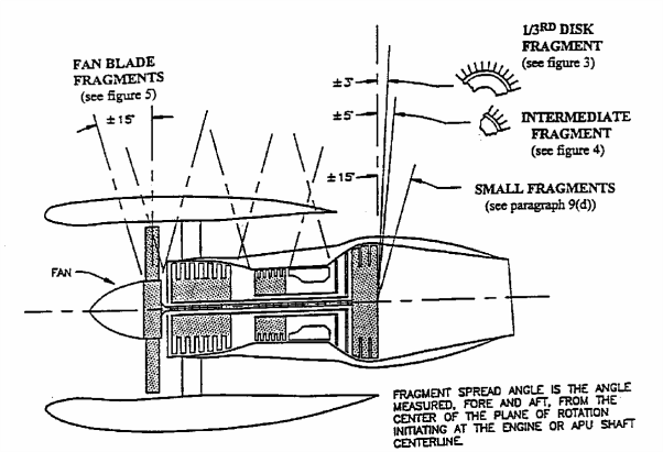
FIGURE 1 – ESTIMATED PATH OF FRAGMENTS
g. Impact Area. The impact area is that area of the aeroplane likely to be impacted by uncontained fragments generated during a rotor failure (see Paragraph 9).
h. Engine and APU Failure Model. A model describing the size, mass, spread angle, energy level and number of engine or APU rotor fragments to be considered when analysing the aeroplane design is presented in Paragraph 9.
7 DESIGN CONSIDERATIONS.
Practical design precautions should be used to minimise the damage that can be caused by uncontained engine and APU rotor fragments. The most effective methods for minimising the hazards from uncontained rotor fragments include location of critical components outside the fragment impact areas or separation, isolation, redundancy, and shielding of critical aeroplane components and/or systems. The following design considerations are recommended:
a. Consider the location of the engine and APU rotors relative to critical components, systems or areas of the aeroplane such as:
(1) Any other engine(s) or an APU that provides an essential function;
(2) Pressurised sections of the fuselage and other primary structure of the fuselage, wings and empennage;
(3) Pilot compartment areas;
(4) Fuel system components, piping and tanks;
(5) Control systems, such as primary and secondary flight controls, electrical power cables, wiring, hydraulic systems, engine control systems, flammable fluid shut-off valves, and the associated actuation wiring or cables;
(6) Any fire extinguisher system of a cargo compartment, an APU, or another engine including electrical wiring and fire extinguishing agent plumbing to these systems;
(7) Engine air inlet attachments and effects of engine case deformations caused by fan blade debris resulting in attachment failures;
(8) Instrumentation essential for continued safe flight and landing;
(9) Thrust reverser systems where inadvertent deployment could be catastrophic; and
(10) Oxygen systems for high altitude aeroplanes, where these are critical due to descent time.
b. Location of Critical Systems and Components. Critical aeroplane flight and engine control cables, wiring, flammable fluid carrying components and lines (including vent lines), hydraulic fluid lines and components, and pneumatic ducts should be located to minimise hazards caused by uncontained rotors and fan blade debris. The following design practices should be considered:
(1) Locate, if possible, critical components or systems outside the likely debris impact areas.
(2) Duplicate and separate critical components or systems, or provide suitable protection if located in debris impact areas.
(3) Protection of critical systems and components can be provided by using airframe structure or supplemental shielding.
These methods have been effective in mitigating the hazards from both single and multiple small fragments within the ± 15 impact area. Separation of multiplicated critical systems and components by at least a distance equal to the 1/2 blade fragment dimension has been accepted for showing minimisation from a single high energy small fragment when at least one of the related multiplicated critical components is shielded by significant structure such as aluminium lower wing skins, pylons, aluminium skin of the cabin pressure vessel, or equivalent structures.
Multiplicated critical systems and components positioned behind less significant structures should be separated by at least a distance equal to the 1/2 blade fragment dimension, and at least one of the multiplicated critical systems should be:
(i) Located such that equivalent protection is provided by other inherent structures such as pneumatic ducting, interiors, bulkheads, stringers, or
(ii) Protected by an additional shield such that the airframe structure and shield material provide equivalent shielding.
(4) Locate fluid shut-offs and actuation means so that flammable fluid can be isolated in the event of damage to the system.
(5) Minimise the flammable fluid spillage which could contact an ignition source.
(6) For airframe structural elements, provide redundant designs or crack stoppers to limit the subsequent tearing which could be caused by uncontained rotor fragments.
(7) Locate fuel tanks and other flammable fluid systems and route lines (including vent lines) behind aeroplane structure to reduce the hazards from spilled fuel or from tank penetrations. Fuel tank explosion-suppression materials, protective shields or deflectors on the fluid lines, have been used to minimise the damage and hazards.
c. External Shields and Deflectors. When shields, deflection devices or aeroplane structure are proposed to be used to protect critical systems or components, the adequacy of the protection, including mounting points to the airframe structure, should be shown by testing or validated analyses supported by test data, using the fragment energies supplied by the engine or APU manufacturer or those defined in Paragraph 9. For protection against engine small fragments, as defined in Paragraph 9, no quantitative validation as defined in Paragraph 10 is required if equivalency to the penetration resistant structures listed (e.g. pressure cabin skins, etc.) is shown.
8 ACCEPTED DESIGN PRECAUTIONS.
Design practices currently in use by the aviation industry that have been shown to reduce the overall risk, by effectively eliminating certain specific risks and reducing the remaining specific risks to a minimum level, are described within this paragraph of the AMC. Aeroplane designs submitted for evaluation by the regulatory authorities will be evaluated against these proven design practices.
a. Uncontrolled Fire.
(1) Fire Extinguishing Systems. The engine/APU fire extinguishing systems currently in use rely on a fire zone with a fixed compartment air volume and a known air exchange rate to extinguish a fire. The effectiveness of this type of system along with firewall integrity may therefore be compromised for the torn/ruptured compartment of the failed engine/APU. Protection of the aeroplane following this type of failure relies on the function of the fire warning system and subsequent fire switch activation to isolate the engine/APU from airframe flammable fluid (fuel and hydraulic fluid) and external ignition sources (pneumatic and electrical). Fire extinguishing protection of such a compromised system may not be effective due to the extent of damage. Continued function of any other engine, APU or cargo compartment fire warning and extinguisher system, including electrical wiring and fire extinguishing agent plumbing, should be considered as described in Paragraph 7.
(2) Flammable Fluid Shut-off Valve. As discussed above, shut-off of flammable fluid supply to the engine may be the only effective means to extinguish a fire following an uncontained failure, therefore the engine isolation/flammable fluid shut-off function should be assured following an uncontained rotor failure. Flammable fluid shut-off valves should be located outside the uncontained rotor impact area. Shut-off actuation controls that need to be routed through the impact area should be redundant and appropriately separated in relation to the one-third disc maximum dimension.
(3) Fire Protection of Critical Functions. Flammable fluid shut-off and other critical controls should be located so that a fire (caused by an uncontained rotor event) will not prevent actuation of the shut- off function or loss of critical aeroplane functions. If shut-off or other critical controls are located where a fire is possible following an uncontained rotor failure (e.g. in compartments adjacent to fuel tanks) then these items should meet the applicable fire protection guidelines such as ISO 2685:1992 or AC 20-135.
(4) Fuel Tanks. If fuel tanks are located in impact areas, the following precautions should be implemented:
(i) Protection from the effects of fuel leakage should be provided for any fuel tanks located above an engine or APU and within the one-third disc and intermediate fragment impact areas. Dry bays or shielding are acceptable means. The dry bay should be sized based on analysis of possible fragment trajectories through the fuel tank wall and the subsequent fuel leakage from the damaged fuel tank so that fuel will not migrate to an engine, APU or other ignition source during either – flight or ground operation. A minimum drip clearance distance of 10 inches (254 mm) from potential ignition sources of the engine nacelle, for static conditions, has been acceptable (see Figure 2).
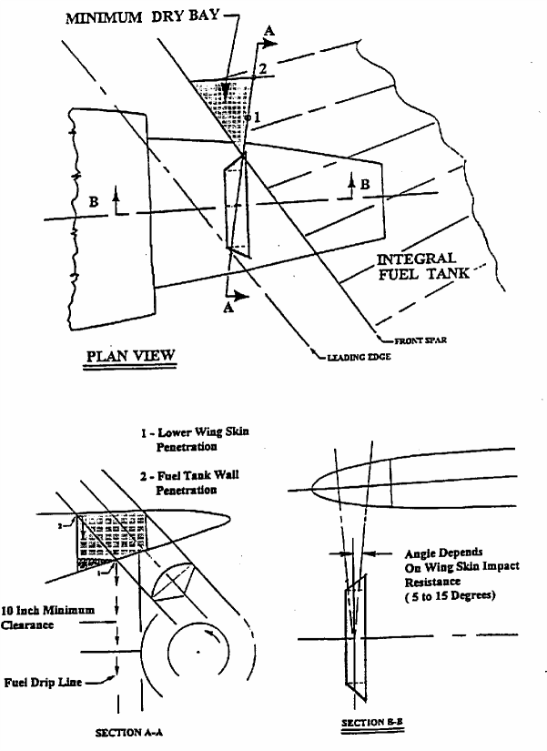
FIGURE 2 – DRY BAY SIZING DETERMINATION EXAMPLE
(ii) Fuel tank penetration leak paths should be determined and evaluated for hazards during flight and ground phases of operation. If fuel spills into the airstream away from the aeroplane no additional protection is needed. Additional protection should be considered if fuel could spill, drain or migrate into areas housing ignition sources, such as engine or APU inlets or wheel wells. Damage to adjacent systems, wiring etc., should be evaluated regarding the potential that an uncontained fragment will create both an ignition source and fuel source. Wheel brakes may be considered as an ignition source during take-off and initial climb. Protection of the wheel wells may be provided by airflow discharging from gaps or openings, preventing entry of fuel, a ventilation rate precluding a combustible mixture or other provisions indicated in CS 23.863 and CS 25.863.
(iii) Areas of the aeroplane where flammable fluid migration is possible that are not drained and vented and have ignition sources or potential ignition sources should be provided with a means of fire detection and suppression and be explosion vented or equivalently protected.
b. Loss of Thrust.
(1) Fuel Reserves. The fuel reserves should be isolatable such that damage from a disc fragment will not result in loss of fuel required to complete the flight or a safe diversion. The effects of fuel loss, and the resultant shift of centre of gravity or lateral imbalance on aeroplane controllability should also be considered.
(2) Engine Controls. Engine control cables and/or wiring for the remaining powerplants that pass through the impact area should be separated by a distance equal to the maximum dimension of a one- third disc fragment or the maximum extent possible.
(3) Other Engine Damage. Protection of any other engines from some fragments should be provided by locating critical components, such as engine accessories essential for proper engine operation (e.g., high pressure fuel lines, engine controls and wiring, etc.), in areas where inherent shielding is provided by the fuselage, engine or nacelle (including thrust reverser) structure (see Paragraph 7).
c. Loss of Aeroplane Control
(1) Flight Controls. Elements of the flight control system should be adequately separated or protected so that the release of a single one-third disc fragment will not cause loss of control of the aeroplane in any axis. Where primary flight controls have duplicated (or multiplicated) elements, these elements should be located to prevent all elements in any axis being lost as a result of the single one- third disc fragment. Credit for maintaining control of the aeroplane by the use of trim controls or other means may be obtained, providing evidence shows that these means will enable the pilot to retain control.
(2) Emergency Power. Loss of electrical power to critical functions following an uncontained rotor event should be minimised. The determination of electrical system criticality is dependent upon aeroplane operations. For example, aeroplanes approved for Extended Twin Engine Operations (ETOPS) that rely on alternate power sources such as hydraulic motor generators or APUs may be configured with the electrical wiring separated to the maximum extent possible within the one-third disc impact zone.
(3) Hydraulic Supply. Any essential hydraulic system supply that is routed within an impact area should have means to isolate the hydraulic supply required to maintain control of the aeroplane. The single one-third disc should not result in loss of all essential hydraulic systems or loss of all flight controls in any axis of the aeroplane.
(4) Thrust reverser systems. The effect of an uncontained rotor failure on inadvertent in-flight deployment of each thrust reverser and possible loss of aeroplane control shall be considered. The impact area for components located on the failed engine may be different from the impact area defined in Paragraph 6. If uncontained failure could cause thrust reverser deployment, the engine manufacturer should be consulted to establish the failure model to be considered. One acceptable method of minimisation is to locate reverser restraints such that not all restraints can be made ineffective by the fragments of a single rotor.
d. Passenger and Crew Incapacitation.
(1) Pilot Compartment. The pilot compartment of large aeroplanes should not be located within the ± 15° spread angle of any engine rotor stage or APU rotor stage that has not been qualified as contained, unless adequate shielding, deflectors or equivalent protection is provided for the rotor stage in accordance with Paragraph 7c. Due to design constraints inherent in smaller CS-23 aeroplanes, it is not considered practical to locate the pilot compartment outside the ±15° spread angle. Therefore for other aeroplanes (such as new CS-23 commuter category aeroplanes) the pilot compartment area should not be located within the ±5° spread angle of any engine rotor stage or APU rotor stage unless adequate shielding, deflectors, or equivalent protection is provided for the rotor stage in accordance with Paragraph 7c of this AMC, except for the following:
(i) For derivative CS-23 category aeroplanes where the engine location has been previously established, the engine location in relation to the pilot compartment need not be changed.
(ii) For non-commuter CS-23 category aeroplanes, satisfactory service experience relative to rotor integrity and containment in similar engine installations may be considered in assessing the acceptability of installing engines in line with the pilot compartment.
(iii) For non-commuter new CS-23 category aeroplanes, where due to size and/or design considerations the ± 5° spread angle cannot be adhered to, the pilot compartment/engine location should be analysed and accepted in accordance with Paragraphs 9 and 10.
(2) Pressure Vessel. For aeroplanes that are certificated for operation above 41,000 feet, the engines should be located such that the pressure cabin cannot be affected by an uncontained one- third or intermediate disc fragment. Alternatively, it may be shown that rapid decompression due to the maximum hole size caused by fragments within the ± 15° zone and the associated cabin pressure decay rate will allow an emergency descent without incapacitation of the flightcrew or passengers. A pilot reaction time of 17 seconds for initiation of the emergency decent has been accepted. Where the pressure cabin could be affected by a one-third disc or intermediate fragments, design precautions should be taken to preclude incapacitation of crew and passengers. Examples of design precautions that have been previously accepted are:
(i) Provisions for a second pressure or bleed down bulkhead outside the impact area of a one- third or intermediate disc fragment.
(ii) The affected compartment in between the primary and secondary bulkhead was made inaccessible, by operating limitations, above the minimum altitude where incapacitation could occur due to the above hole size.
(iii) Air supply ducts running through this compartment were provided with non-return valves to prevent pressure cabin leakage through damaged ducts.
NOTE: If a bleed down bulkhead is used it should be shown that the rate of pressure decay and minimum achieved cabin pressure would not incapacitate the crew, and the rate of pressure decay would not preclude a safe emergency descent.
e. Structural Integrity. Installation of tear straps and shear ties within the uncontained fan blade and engine rotor debris zone to prevent catastrophic structural damage has been utilised to address this threat.
9. ENGINE AND APU FAILURE MODEL.
The safety analysis recommended in Paragraph 10 should be made using the following engine and APU failure model, unless for the particular engine/APU type concerned, relevant service experience, design data, test results or other evidence justify the use of a different model.
a. Single One-Third Disc fragment. It should be assumed that the one-third disc fragment has the maximum dimension corresponding to one-third of the disc with one-third blade height and a fragment spread angle of ± 3°. Where energy considerations are relevant, the mass should be assumed to be one-third of the bladed disc mass and its energy, the translational energy (i.e., neglecting rotational energy) of the sector travelling at the speed of its c.g. location as defined in Figure 3.
b. Intermediate Fragment. It should be assumed that the intermediate fragment has a maximum dimension corresponding to one-third of the bladed disc radius and a fragment spread angle of ± 5°. Where energy considerations are relevant, the mass should be assumed to be 1/30 of the bladed disc mass and its energy the transitional energy (i.e. neglecting rotational energy) of the piece travelling at rim speed (see Figure 4).
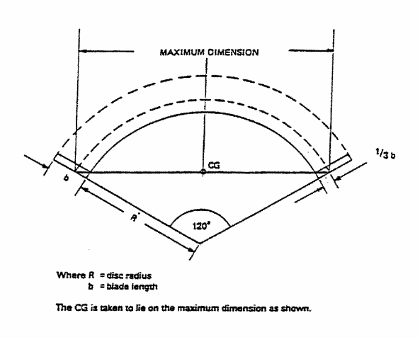
FIGURE 3 – SINGLE ONE-THIRD ROTOR FRAGMENT
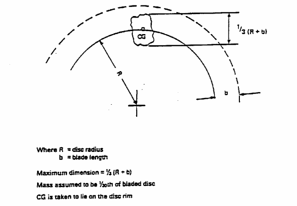
FIGURE 4 – INTERMEDIATE FRAGMENT
c. Alternative Engine Failure Model. For the purpose of the analysis, as an alternative to the engine failure model of Paragraphs 9a and b, the use of a single one-third piece of disc having a fragment spread angle ± 5° would be acceptable, provided the objectives of Paragraph 10c are satisfied.
d. Small Fragments. It should be assumed that small fragments (shrapnel) range in size up to a maximum dimension corresponding to the tip half of the blade airfoil (with exception of fan blades) and a fragment spread angle of ± 15°. Service history has shown that aluminium lower wing skins, pylons, and pressure cabin skin and equivalent structures typically resist penetration from all but one of the most energetic of these fragments. The effects of multiple small fragments should also be considered. Penetration of less significant structures such as fairings, empennage, control surfaces and unpressurised unpressurized skin has typically occurred at the rate of 2½ percent of the number of blades of the failed rotor stage. Refer to paragraph 7b and 7c for methods of minimisation of the hazards. Where the applicant wishes to show compliance by considering the energy required for penetration of structure (or shielding) the engine manufacturer should be consulted for guidance as to the size and energy of small fragments within the impact area.
For APUs, where energy considerations are relevant, it should be assumed that the mass will correspond to the above fragment dimensions and that it has a translational energy level of one percent of the total rotational energy of the original rotor stage.
e. Fan Blade Fragment. It should be assumed that the fan blade fragment has a maximum dimension corresponding to the blade tip with one-third the blade airfoil height and a fragment spread angle of ± 15°. Where energy considerations are relevant the mass should be assumed to be corresponding to the one-third of the airfoil including any part span shroud and the transitional energy (neglecting rotational energy) of the fragment travelling at the speed of its c.g. location as defined in Figure 5. As an alternative, the engine manufacturer may be consulted for guidance as to the size and energy of the fragment.
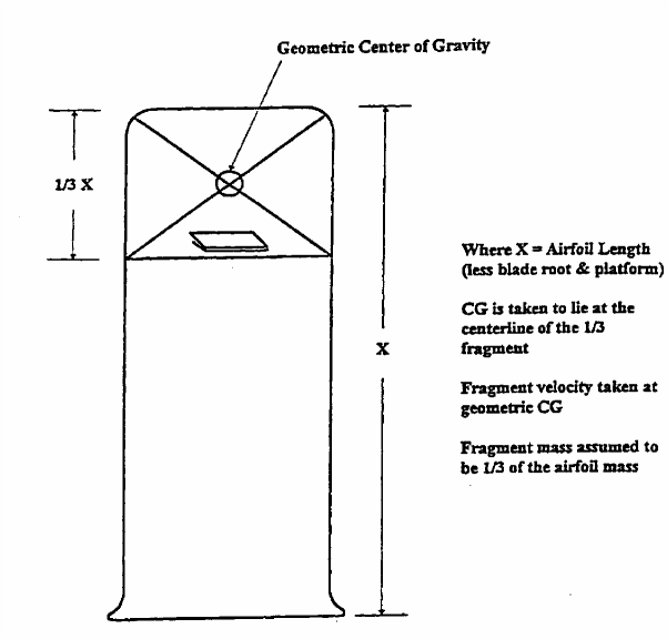
FIGURE 5 – FAN BLADE FRAGMENT DEFINITION
f. Critical Engine Speed. Where energy considerations are relevant, the uncontained rotor event should be assumed to occur at the engine or APU shaft red line speed.
g. APU Failure Model. For all APU's, the installer also needs to address any hazard to the aeroplane associated with APU debris (up to and including a complete rotor where applicable) exiting the tailpipe. Paragraphs 9g(1) or (2) below or applicable service history provided by the APU manufacturer may be used to define the size, mass, and energy of debris exiting that tailpipe. The APU rotor failure model applicable for a particular APU installation is dependent upon the provisions of CS-APU that were utilised for receiving approval:
(1) For APU's where rotor integrity has been demonstrated in accordance with CS-APU, i.e. without specific containment testing, Paragraphs 9a, b, and d, or Paragraphs 9c and 9d apply.
(2) For APU rotor stages qualified as contained in accordance with CS-APU, historical data shows that in-service uncontained failures have occurred. These failure modes have included bi-hub, overspeed, and fragments missing the containment ring which are not addressed by the CS-APU containment test. In order to address these hazards, the installer should use the APU small fragment definition of Paragraph 9d or substantiated in-service data supplied by the APU manufacturer.
10 SAFETY ANALYSIS.
The numerical assessment requested in Paragraph 10c(3) is derived from methods previously prescribed in ACJ No. 2 to CS 25.903(d)(1). The hazard ratios provided are based upon evaluation of various configurations of large aeroplanes, made over a period of time, incorporating practical methods of minimising the hazard to the aeroplane from uncontained engine debris.
a. Analysis. An analysis should be made using the engine/APU model defined in Paragraph 9 to determine the critical areas of the aeroplane likely to be damaged by rotor debris and to evaluate the consequences of an uncontained failure. This analysis should be conducted in relation to all normal phases of flight, or portions thereof.
NOTE: APPENDIX 1 provides additional guidance for completion of the numerical analysis requested by this paragraph.
(1) A delay of at least 15 seconds should be assumed before start of the emergency engine shut down. The extent of the delay is dependent upon circumstances resulting from the uncontained failure including increased flightcrew workload stemming from multiplicity of warnings which require analysis by the flightcrew.
(2) Some degradation of the flight characteristics of the aeroplane or operation of a system is permissible, provided the aeroplane is capable of continued safe flight and landing. Account should be taken of the behaviour of the aeroplane under asymmetrical engine thrust or power conditions together with any possible damage to the flight control system, and of the predicted aeroplane recovery manoeuvre.
(3) When considering how or whether to mitigate any potential hazard identified by the model, credit may be given to flight phase, service experience, or other data, as noted in Paragraph 7.
b. Drawings. Drawings should be provided to define the uncontained rotor impact threat relative to the areas of design consideration defined in Paragraphs 7a(1) through (10) showing the trajectory paths of engine and APU debris relative to critical areas. The analysis should include at least the following:
(1) Damage to primary structure including the pressure cabin, engine/APU mountings and airframe surfaces.
NOTE: Any structural damage resulting from uncontained rotor debris should be considered catastrophic unless the residual strength and flutter criteria of ACJ 25.571(a) subparagraph 2.7.2 can be met without failure of any part of the structure essential for completion of the flight. In addition, the pressurised compartment loads of CS 25.365(e)(1) and (g) must be met.
(2) Damage to any other engines (the consequences of subsequent uncontained debris from the other engine(s), need not be considered).
(3) Damage to services and equipment essential for safe flight and landing (including indicating and monitoring systems), particularly control systems for flight, engine power, engine fuel supply and shut-off means and fire indication and extinguishing systems.
(4) Pilot incapacitation, (see also paragraph 8 d(1)).
(5) Penetration of the fuel system, where this could result in the release of fuel into personnel compartments or an engine compartment or other regions of the aeroplane where this could lead to a fire or explosion.
(6) Damage to the fuel system, especially tanks, resulting in the release of a large quantity of fuel.
(7) Penetration and distortion of firewalls and cowling permitting a spread of fire.
(8) Damage to or inadvertent movement of aerodynamic surfaces (e.g.. flaps, slats, stabilisers, ailerons, spoilers, thrust reversers, elevators, rudders, strakes, winglets, etc.) and the resultant effect on safe flight and landing.
c. Safety Analysis Objectives. It is considered that the objective of minimising hazards will have been met if:
(1) The practical design considerations and precautions of Paragraphs 7 and 8 have been taken;
(2) The safety analysis has been completed using the engine/APU model defined in Paragraph 9;
(3) For CS-25 large aeroplanes and CS-23 commuter category aeroplanes, the following hazard ratio guidelines have been achieved:
(i) Single One-Third Disc Fragment. There is not more than a 1 in 20 chance of catastrophe resulting from the release of a single one-third disc fragment as defined in Paragraph 9a.
(ii) Intermediate Fragment. There is not more than a 1 in 40 chance of catastrophe resulting from the release of a piece of debris as defined in Paragraph 9b.
(iii) Multiple Disc Fragments. (Only applicable to any duplicated or multiplicated system when all of the system channels contributing to its functions have some part which is within a distance equal to the diameter of the largest bladed rotor, measured from the engine centreline). There is not more than 1 in 10 chance of catastrophe resulting from the release in three random directions of three one-third fragments of a disc each having a uniform probability of ejection over the 360° (assuming an angular spread of ±3° relative to the plane of the disc) causing coincidental damage to systems which are duplicated or multiplicated.
NOTE: Where dissimilar systems can be used to carry out the same function (e.g. elevator control and pitch trim), they should be regarded as duplicated (or multiplicated) systems for the purpose of this subparagraph provided control can be maintained.
The numerical assessments described above may be used to judge the relative values of minimisation. The degree of minimisation that is feasible may vary depending upon aeroplane size and configuration and this variation may prevent the specific hazard ratio from being achieved. These levels are design goals and should not be treated as absolute targets. It is possible that any one of these levels may not be practical to achieve.
(4) For newly designed non-commuter CS-23 aeroplanes the chance of catastrophe is not more than twice that of Paragraph 10(c)(3)(i), (ii) and (iii) for each of these fragment types.
(5) A numerical risk assessment is not requested for the single fan blade fragment, small fragments, and APU and engine rotor stages which are qualified as contained.
d. APU Analysis For APU's that are located where no hazardous consequences would result from an uncontained failure, a limited qualitative assessment showing the relative location of critical systems/components and APU impact areas is all that is needed. If critical systems/components are located within the impact area, more extensive analysis is needed. For APUs which have demonstrated rotor integrity only, the failure model outlined in Paragraph 9g(1) should be considered as a basis for this safety assessment. For APU rotor stages qualified as contained per CS–APU, the aeroplane safety analysis may be limited to an assessment of the effects of the failure model outlined in Paragraph 9g(2).
e. Specific Risk The aeroplane risk levels specified in Paragraph 10c, resulting from the release of rotor fragments, are the mean values obtained by averaging those for all rotors on all engines of the aeroplane, assuming a typical flight. Individual rotors or engines need not meet these risk levels nor need these risk levels be met for each phase of flight if either:
(1) No rotor stage shows a higher level of risk averaged throughout the flight greater than twice those stated in Paragraph 10c.
NOTE: The purpose of this Paragraph is to ensure that a fault which results in repeated failures of any particular rotor stage design, would have only a limited effect on aeroplane safety.
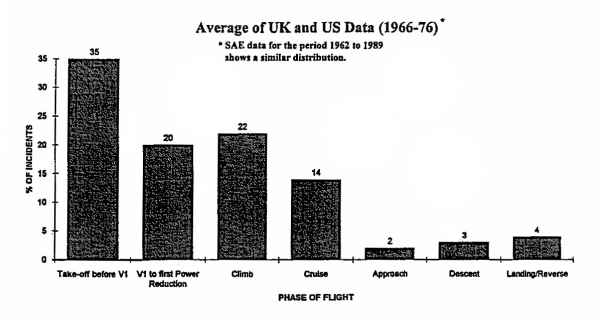
FIGURE 6 – ALL NON-CONTAINMENTS BY PHASE OF FLIGHT
(2) Where failures would be catastrophic in particular portions of flight, allowance is made for this on the basis of conservative assumptions as to the proportion of failures likely to occur in these phases. A greater level of risk could be accepted if the exposure exists only during a particular phase of flight e.g., during take-off. The proportional risk of engine failure during the particular phases of flight is given in SAE Papers referenced in Paragraph 4d. See also data contained in the CAA paper "Engine Non-Containments – The CAA View", which includes Figure 6. This paper is published in NASA Report CP-2017, "An Assessment of Technology for Turbo-jet Engine Rotor Failures", dated August 1977.
Appendix 1 to AMC 20-128A User’s Manual
ED Decision 2003/12/RM
RISK ANALYSIS METHODOLOGY for UNCONTAINED ENGINE/APU FAILURE
INDEX
1.0 GENERAL
2.0 SCOPE
3.0 FUNDAMENTAL COMPONENTS OF A SAFETY AND RISK ANALYSIS
4.0 ASSUMPTIONS
5.0 PLOTTING
6.0 METHODOLOGY – PROBABILITY ASSESSMENT
7.0 RESULTS ASSESSMENT
|
FIGURE 1 |
EXAMPLE – HAZARD TREE |
|
FIGURE 2 |
EXAMPLE – SYSTEM LOADING MATRIX |
|
FIGURE 3 |
TRI-SECTOR ROTOR BURST |
|
FIGURE 4 |
TYPICAL LAYOUT OF SYSTEMS IN ROTOR PLANE |
|
FIGURE 5 |
TRAJECTORY RANGE PLOTTING |
|
FIGURE 6 |
TYPICAL TRAJECTORY PLOTTING |
|
FIGURE 7 |
DEFINITION – THREAT WINDOW |
|
FIGURE 8 |
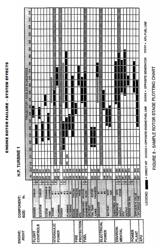
SAMPLE ROTOR STAGE PLOTTING CHART |
1.0 GENERAL
1.1 The design of aeroplane and engine systems and the location of the engines relative to critical systems and structure have a significant impact on survivability of the aeroplane following an uncontained engine failure. CS 23.903(b)(1) and 25.903(d)(1) of the EASA Certification Specifications (CS) require that design precautions be taken to minimise the hazard to the aeroplane due to uncontained failures of engine or auxiliary power unit (APU). AMC 20-128A provides guidance for demonstrating compliance with these requirements.
1.2 As a part of this compliance demonstration, it is necessary to quantitatively assess the risk of a catastrophic failure in the event of an uncontained engine failure. This User’s Manual describes an acceptable method for this purpose.
1.3 The objective of the risk analysis is to measure the remaining risk after prudent and practical design considerations have been taken. Since each aeroplane would have unique features which must be considered when applying the methods described in this manual, there should be some flexibility in the methods and procedures.
1.4 It is a preferred approach to use these methods throughout the development of an aeroplane design to identify problem areas at an early stage when appropriate design changes are least disruptive. It is also advisable to involve the European Aviation Safety Agency (EASA) in this process at an early stage when appropriate interpretation of the methodology and documentation requirements can be established.
1.5 It should be noted that although the risk analysis produces quantitative results, subjective assessments are inherent in the methods of the analysis regarding the criticality of specific types of aeroplane component failures. Assumptions for such assessments should be documented along with the numerical results.
1.6 Aeroplane manufacturers have each developed their own method of assessing the effects of rotor failure, as there are many ways to get to the same result. This User’s Manual identifies all the elements that should be contained in an analysis, so that it can be interpreted by a person not familiar with such a process.
1.7 The intent of this manual therefore is to aid in establishing how an analysis is prepared, without precluding any technological advances or existing proprietary processes.
1.8 AMC 20-128A makes allowance for the broad configuration of the aeroplane as such damage to the structure due to rotor failure generally allows for little flexibility in design. System lay-out within a rotor burst zone, however, can be optimized.
1.9 Damage to structure, which may involve stress analysis, generally can be analyzed separately, and later coordinated with simultaneous system effects.
1.10 For an analysis of the effects on systems due to a rotor failure the aeroplane must be evaluated as a whole; and a risk analysis must specifically highlight all critical cases identified which have any potential to result in a catastrophe.
1.11 Such an analysis can then be used to establish that reasonable precautions have been taken to minimise the hazards, and that the remaining hazards are an acceptable risk.
1.12 A safety and a risk analysis are interdependent, as the risk analysis must be based on the safety analysis.
The safety analysis therefore is the starting point that identifies potential hazardous or catastrophic effects from a rotor failure and is the basic tool to minimise the hazard in accordance with the guidelines of AMC 20-128A.
1.13 The risk analysis subsequently assesses and quantifies the residual risk to the aeroplane.
2.0 SCOPE
The following describes the scope of analyses required to assess the aeroplane risk levels against the criteria set forth in Paragraph 10 of AMC 20-128A.
2.1 Safety
Analysis is required to identify the critical hazards that may be numerically analyzed (hazards remaining after all practical design precautions have been taken).
Functional criticality will vary by aeroplane and may vary by flight phase.
Thorough understanding of each aeroplane structure and system functions is required to establish the criticality relative to each fragment trajectory path of the theoretical failure.
Assistance from experts within each discipline is typically required to assure accuracy of the analysis in such areas as effects of fuel tank penetration on leakage paths and ignition hazards, thrust level control (for loss of thrust assessment), structural capabilities (for fuselage impact assessment), aeroplane controllability (for control cables impact assessment), and fuel asymmetry.
2.2 Risk
For each remaining critical hazard, the following assessments may be prepared using the engine/APU failure models as defined in Paragraph 9 of AMC 20-128A:
a. Flight mean risk for single 1/3 disc fragment.
b. Flight mean risk for single intermediate fragment.
c. Flight mean risk for alternate model (when used as an alternate to the 1/3 disc fragment and intermediate fragment).
d. Multiple 1/3 disc fragments for duplicated or multiplicated systems.
e. Specific risk for single 1/3 disc fragment and single intermediate fragment.
f. Specific risk for any single disc fragment that may result in catastrophic structural damage.
The risk level criteria for each failure model are defined in Paragraph 10 of AMC 20-128A.
3.0 FUNDAMENTAL COMPONENTS OF A SAFETY AND RISK ANALYSIS
3.1 The logical steps for a complete analysis are:
a. Establish at the design definition the functional hazards that can arise from the combined or concurrent failures of individual systems, including multiplicated systems and critical structure.
b. Establish a Functional Hazard Tree (see Figure 1), or a System Matrix (see Figure 2) that identifies all system interdependencies and failure combinations that must be avoided (if possible) when locating equipment in the rotor burst impact area.
In theory, if this is carried out to the maximum, no critical system hazards other than opposite engine or fuel line hits would exist.
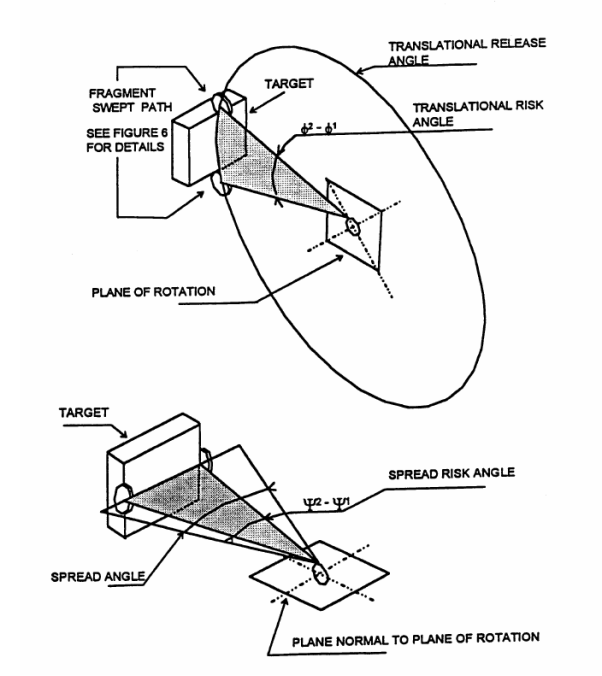
c. Establish the fragment trajectories and trajectory ranges both for translational and spread risk angles for each damage. Plot these on a chart or graph, and identify the trajectory ranges that could result in hazardous combinations (threats) as per the above system matrix or functional hazard analysis.
d. Apply risk factors, such as phase of flight or other, to these threats, and calculate the risk for each threat for each rotor stage.
e. Tabulate, summarize and average all cases.
3.2 In accordance with AMC 20-128A the risk to the aeroplane due to uncontained rotor failure is assessed to the effects, once such a failure has occurred.
The probability of occurrence of rotor failure, as analyzed with the probability methods of AMC 25.1309 (i.e. probability as a function of critical uncontained rotor failure rate and exposure time), does not apply.
3.3 The total risk level to the aeroplane, as identified by the risk analysis, is the mean value obtained by averaging the values of all rotor stages of all engines of the aeroplane, expressed as Flight Mean Risk.
4.0 ASSUMPTIONS
4.1 The following conservative assumptions, in addition to those in Paragraphs 10(a)(1), (2) and (3) of AMC 20-128A, have been made in some previous analyses. However, each aeroplane design may have unique characteristics and therefore a unique basis for the safety assessment leading to the possibility of different assumptions. All assumptions should be substantiated within the analysis:
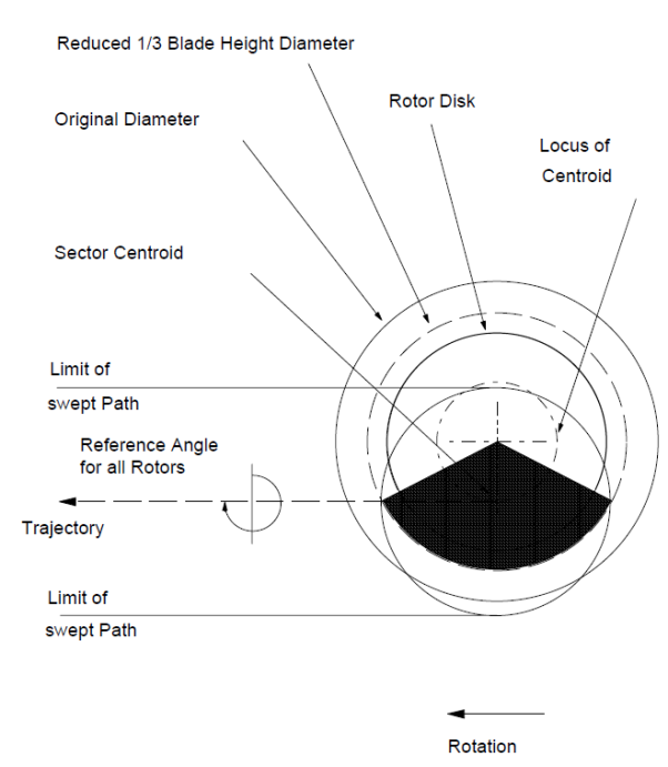
a. The 1/3 disc fragment as modeled in Paragraph 9(a) of the AMC 20-128A travels along a trajectory path that is tangential to the sector centroid locus, in the direction of rotor rotation (Refer to Figure 3).
The sector fragment rotates about its centroid without tumbling and sweeps a path equal to twice the greatest radius that can be struck from the sector centroid that intersects its periphery.
The fragment is considered to possess infinite energy, and therefore to be capable of severing lines, wiring, cables and unprotected structure in its path, and to be undeflected from its original trajectory unless deflection shields are fitted. However, protective shielding or an engine being impacted may be assumed to have sufficient mass to stop even the most energetic fragment.
b. The probability of release of debris within the maximum spread angle is uniformly distributed over all directions.
c. The effects of severed electrical wiring are dependent on the configuration of the affected system. In general, severed wiring is assumed to not receive inadvertent positive voltage for any significant duration.
d. Control cables that are struck by a fragment disconnect.
e. Hydraulically actuated, cable driven control surfaces, which do not have designated “fail to” settings, tend to fail to null when control cables are severed. Subsequent surface float is progressive and predictable.
f. Systems components are considered unserviceable if their envelope has been touched. In case of an engine being impacted, the nacelle structure may be regarded as engine envelope, unless damage is not likely to be hazardous.
g. Uncontained events involving in-flight penetration of fuel tanks will not result in fuel tank explosion.
h. Unpowered flight and off-airport landings, including ditching, may be assumed to be not catastrophic to the extent validated by accident statistics or other accepted factors.
i. Damage to structure essential for completion of flight is catastrophic (Ref. AMC 20-128A, Paragraph 10.b(1)).
j. The flight begins when engine power is advanced for takeoff and ends after landing when turning off the runway.
5.0 PLOTTING
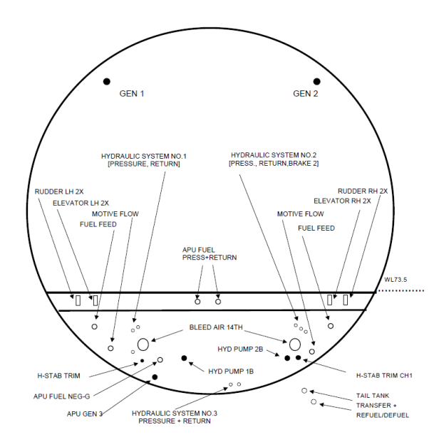
5.1 Cross-section and plan view layouts of the aeroplane systems in the ranges of the rotor burst impact areas should be prepared, either as drawings, or as computer models
These layouts should plot the precise location of the critical system components, including fuel and hydraulic lines, flight control cables, electric wiring harnesses and junction boxes, pneumatic and environmental system ducting, fire extinguishing; critical structure, etc.
5.2 For every rotor stage a plane is developed. Each of these planes contains a view of all the system components respective outer envelopes, which is then used to generate a cross-section. See Figure 4.
5.3 Models or drawings representing the various engine rotor stages and their fore and aft deviation are then generated.
5.4 The various trajectory paths generated for each engine rotor stage are then superimposed on the cross-section layouts of the station planes that are in the range of that potential rotor burst in order to study the effects (see Figure 5). Thus separate plots are generated for each engine rotor stage or rotor group.
To reduce the amount of an analysis the engine rotor stages may also be considered as groups, as applicable for the engine type, using the largest rotor stage diameter of the group.
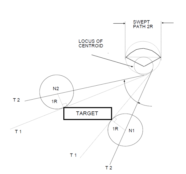
5.5 These trajectory paths may be generated as follows and as shown in Figure 6:
a. Two tangent lines T1 are drawn between the locus of the centroid and the target envelope.
b. At the tangent line touch points, lines N1 and N2 normal to the tangent lines, are drawn with the length equal to the radius of the fragment swept path (as also shown in Figure 1).
c. Tangent lines T2 are drawn between the terminal point of the normal lines and the locus of the centroid. The angle between these two tangent lines is the translational risk angle.
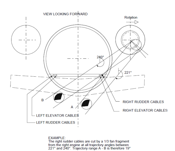
5.6 The entry and exit angles are then calculated.
5.7 The initial angle of intersection and the final angle of intersection are recorded, and the trajectories in between are considered to be the range of trajectories in which this particular part would be impacted by a rotor sector, and destroyed (i.e. the impact area).
The intersections thus recorded are then entered on charts in tabular form so that the simultaneous effects can be studied. Refer to Figure 8.
Thus it will be seen that the total systems’ effects can be determined and the worst cases identified.
5.9 If a potentially serious multiple system damage case is identified, then a more detailed analysis of the trajectory range will be carried out by breaking the failure case down into the specific fore-aft spread angle, using the individual rotor stage width instead of combined groups, if applicable.
6.0 METHODOLOGY – PROBABILITY ASSESSMENT
6.1 Those rotor burst cases that have some potential of causing a catastrophe are evaluated in the analysis in an attempt to quantify an actual probability of a catastrophe, which will, in all cases, depend on the following factors:
a. The location of the engine that is the origin of the fragment, and its direction of rotation.
b. The location of critical systems and critical structure.
c. The rotor stage and the fragment model.
d. The translational trajectory of the rotor fragment,
e. The specific spread angle range of the fragment.
f. The specific phase of the flight at which the failure occurs.
g. The specific risk factor associated with any particular loss of function.
6.2 Engine Location
The analysis should address the effects on systems during one flight after a single rotor burst has occurred, with a probability of 1.0. As the cause may be any one of the engines, the risk from each engine is later averaged for the number of engines.
The analysis trajectory charts will then clearly show that certain system damage is unique to rotor fragments from a particular engine due to the direction of rotation, or, that for similar system damage the trajectory range varies considerably between engines.
A risk summary should table each engine case separately with the engine location included.
6.3 Rotor Element
The probability of rotor failure is assumed to be 1.0 for each of all rotor stages. For the analysis the individual risk(s) from each rotor stage of the engine should be assessed and tabled.
6.4 Translational Risk Angle
The number of degrees of included arc (out of 360) at which a fragment intersects the component/structure being analyzed. Refer to Figure 6 and Figure 7.
6.5 Trajectory Probability (P)
The probability of a liberated rotor fragment leaving the engine case is equal over 360, thus the probability P of that fragment hitting a system component is the identified Translational Risk Angle ɸ in degrees °, divided by 360, i.e.
![]()
or
![]()
6.6 Spread Angle
If the failure model of the analysis assumes a (fore and aft) spread of ± 5°, then the spread angle is a total of 10°. If a critical component can only be hit at a limited position within that spread, then the exposure of that critical component can then be factored according to the longitudinal position within the spread angle, e.g.:
![]()
If a component can only be hit at the extreme forward range of +4° to +5°, then the factor is .1 (for one degree out of 10).
6.7 Threat Window
The definition of a typical threat window is shown in Figure 7.
6.8 Phase of Flight
Certain types of system damage may be catastrophic only during a specific portion of the flight profile, such as a strike on the opposite engine during take-off after V1 (i.e. a probability of 1.0), while with altitude a straight-ahead landing may be possible under certain favourable conditions (e.g. a probability of less than 1.0). The specific case can then be factored accordingly.
6.8.1 The most likely time for an uncontained rotor failure to occur is during take-off, when the engine is under highest stress. Using the industry accepted standards for the percentage of engine failures occurring within each flight phase, the following probabilities are assumed:
|
Take-off before V1 |
35% |
|
V1 to first power reduction |
20% |
|
Climb |
22% |
|
Cruise |
14% |
|
Descent |
3% |
|
Approach |
2% |
|
Landing/Reverse |
4% |
6.8.2 The flight phase failure distribution above is used in the calculations of catastrophic risk for all cases where this risk varies with flight phase.
![]()
6.9 Other Risk Factors
Risks such as fire, loss of pressurization, etc., are individually assessed for each case where applicable, using conservative engineering judgment. This may lead to a probability of catastrophe (i.e., risk factor) smaller than 1.0.
6.9.1 The above probabilities and factors are used in conjunction with the critical trajectory range defined to produce a probability of the specific event occurring from any random rotor burst.
This value is then factored by the "risk" factor assessed for the case, to derive a calculated probability of catastrophe for each specific case.
Typical conditional probability values for total loss of thrust causing catastrophic consequences are:
|
Phase |
Dp |
Risk |
|
T.O.–V1 to first power reduction |
0.20 |
1.0 |
|
Climb |
0.22 |
0.4 |
|
Cruise |
0.14 |
0.2 |
|
Descent |
0.03 |
0.4 |
|
Approach |
0.02 |
0.4 |
6.10 All individual case probabilities are then tabled and summarised.
6.11 The flight mean values are obtained by averaging those for all discs or rotor stages on all engines across a nominal flight profile.
The following process may be used to calculate the flight mean value for each Failure Model:
a. Establish from the table in Figure 8 the threat windows where, due to combination of individual damages, a catastrophic risk exists.
b. For each stage case calculate the risk for all Critical Hazards
c. For each stage case apply all risk factors, and, if applicable, factor for Flight Phase-Failure distribution
d. For each engine, average all stages over the total number of engine stages
e. For each aeroplane, average all engines over the number of engines.
7.0 RESULTS ASSESSMENT
7.1 An applicant may show compliance with CS 23.903(b)(1) and CS 25.903(d)(1) using guidelines set forth in AMC 20-128A. The criteria contained in the AMC may be used to show that:
a. Practical design precautions have been taken to minimise the damage that can be caused by uncontained engine debris, and
b. Acceptable risk levels, as specified in AMC 20-128A, Paragraph 10, have been achieved for each critical Failure Model.
7.2 The summary of the applicable risk level criteria is shown in Table 1 below.
Table 1 Summary of Acceptable Risk Level Criteria
|
Requirement |
Criteria |
|
Average 1/3 Disc Fragment |
1 in 20 |
|
Average Intermediate Fragment |
1 in 40 |
|
Average Alternate Model |
1 in 20 @ ± 5 degree Spread Angle |
|
Multiple Disc Fragments |
1 in 10 |
|
Any single fragment (except for structural damage) |
2 x corresponding average criterion |
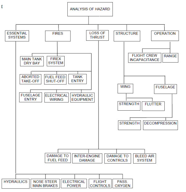
EXAMPLE – HAZARD TREE
FIGURE 1
|
LOC |
COMPONENT |
DAMAGE TO |
SYSTEM LOADED |
DETAIL |
|
LEFT |
AILERON |
CABLES/SURFACE |
HYDRAULIC POWER |
#1 & #3 |
|
RIGHT |
AILERON |
CABLES/SURFACE |
HYDRAULIC POWER |
#2 & #3 |
|
LEFT |
SPOILER - OUTBD MULTI-FUNCTION |
CONTROL/SURFACE |
HYDRAULIC POWER |
#1 |
|
RIGHT |
SPOILER - OUTBD MULTI-FUNCTION |
CONTROL/SURFACE |
HYDRAULIC POWER |
#1 |
|
LEFT |
FLAP-OUTBD |
TRACK/SURFACE |
ELECTRICAL POWER |
AC BUS1 AC ESS |
|
RIGHT |
FLAP-OUTBD |
TRACK/SURFACE |
ELECTRICAL POWER |
AC BUS1 AC ESS |
|
LEFT |
RUDDER |
CABLE |
HYDRAULIC POWER |
#1,#2 |
|
RIGHT |
RUDDER |
CABLE |
HYDRAULIC POWER |
#1,#2 |
|
LEFT |
ELEVATOR |
CABLES Note 1 |
HYDRAULIC POWER |
#1 & #3 |
|
RIGHT |
ELEVATOR |
CABLES Note 1 |
HYDRAULIC POWER |
#2 & #3 |
|
CHAN1 |
PITCH TRIM |
CONTROL/POWER Note 2 |
ELECTRICAL POWER |
AC BUS1 DC BUS1 |
|
CHAN2 |
PITCH TRIM |
CONTROL/POWER Note 2 |
ELECTRICAL POWER |
AC ESS DC ESS |
FLIGHT CONTROLS – SYSTEM LOADING
Note 1:
Same fragment path must not sever:
ON-SIDE cables + OFF-SIDE hydraulic system + HYDRAULIC PWR #3
e.g.: Left elevator cable and HYDRAULIC PWR #2 and #3 or,
Right elevator cable and HYDRAULIC PWR # 1 and # 3
Note 2:
Same fragment path must not sever:
— Both CHAN1 and CHAN2 circuits
— ON-SIDE control circuit + OFF-SIDE power circuit
— OFF-SIDE control circuit + ON-SIDE power circuit
EXAMPLE – SYSTEM LOADING MATRIX
FIGURE 2
TRI-SECTOR ROTOR BURST
FIGURE 3
TYPICAL LAYOUT OF SYSTEMS IN ROTOR PLANE
FIGURE 4
TRAJECTORY RANGE PLOTTING
FIGURE 5
TYPICAL TRAJECTORY PLOTTING
FIGURE 6
DEFINITION - THREAT WINDOW
FIGURE 7