
AMC 20-21 Programme to enhance aeroplane Electrical Wiring Interconnection System (EWIS) maintenance
ED Decision 2008/007/R
This AMC provides acceptable means of compliance for developing enhanced EWIS maintenance for operators, holders of type certificates (TC), holders of supplemental type certificates (STC) and maintenance organisations. The information in this AMC is derived from the maintenance, inspection, and alteration best practices identified through extensive research. This AMC provides an acceptable means of compliance with the appropriate certification, maintenance and operating rules. This AMC promotes a housekeeping philosophy of “protect, clean as you go” when performing maintenance, repair, or alterations on or around aircraft EWIS.
The objective of this AMC is to enhance the maintenance of aircraft EWIS through adoption by the aviation industry of the following:
a. Enhanced Zonal Analysis Procedure (EZAP). This AMC presents an “enhanced zonal analysis procedure” and logic that will benefit all aircraft regardless of whether they currently have a structured Zonal Inspection Programme (ZIP), (see Appendix A. Enhanced Zonal Analysis Logic Diagram and Steps and Appendix B. EZAP Worksheets). Application of this procedure will ensure that appropriate attention is given to wiring installations. Using EZAP it will be possible to select stand-alone inspections (either general or detailed) and tasks to minimise the presence of combustible material. The procedure and logic in this AMC complement existing zonal analysis procedures and will also allow the identification of new wiring tasks for those aircraft that do not have a structured ZIP.
b. Guidance for General Visual Inspection (GVI). This AMC provides clarification of the definition for a GVI as well as guidance on what is expected from such an inspection, whether performed as a stand-alone GVI or as part of a zonal inspection. It is assumed this new inspection standard will be the standard applied by operators, or their maintenance provider, when the new tasks are incorporated in to their maintenance programme.
c. Protection and Caution. This AMC identifies protection and caution to be added to maintenance instructions, thereby enhancing procedures that will lead to minimisation of contamination and accidental damage while working on the aircraft.
The enhanced aircraft wiring maintenance information described in this AMC is intended to improve maintenance and inspection programmes for all aircraft systems. This information, when used appropriately, will improve the likelihood that wiring system degradation, including age-related problems, will be identified and corrected. Therefore, the goal of enhanced wiring maintenance information is to ensure that maintenance actions, such as inspection, repair, overhaul, replacement of parts, and preservation, do not cause a loss of wiring system function, do not cause an increase in the potential for smoke and fire in the aircraft, and do not inhibit the safe operation of the aircraft.
In order to fully realise the objectives of this AMC, operators, TC holders, STC holders and maintenance providers, will need to rethink their current approach to maintaining and modifying aircraft wiring and systems. This may require more than simply updating maintenance manuals and work cards and enhancing training. Maintenance personnel need to be aware that aircraft EWIS should be maintained with the same level of intensity as any other system in the aircraft. They also need to recognise that visual inspection of wiring has inherent limitations. Small defects such as breached or cracked insulations, especially in small gauge wire may not always be apparent. Therefore effective wiring maintenance combines visual inspection techniques with improved wiring maintenance practices and training.
Good wiring maintenance practices should contain a "protect, clean as you go" housekeeping philosophy. In other words, care should be taken to protect wire bundles and connectors during work, and to ensure that all shavings, debris and contamination are cleaned up after work is completed. This philosophy is a proactive approach to wiring system health. Wiring needs to be given special attention when maintenance is being performed on it, or around it. This is especially true when performing structural repairs, work under STCs or field approvals, or other modifications.
To fully achieve the objectives of this AMC it is imperative that all personnel performing maintenance on or around EWIS receive appropriate training (see AMC 20-22: Aeroplane EWIS training programme).
a. The guidance provided in this document is directed to operators, TC applicants and holders, STC applicants and maintenance organisations:
b. The guidance provided in this AMC can be applied to all aeroplane maintenance or inspection programmes. The EZAP in Appendix A of this AMC is specifically directed towards enhancing the maintenance programmes for aircraft whose current programme does not include tasks derived from a process that specifically considers wiring in all zones as the potential source of ignition of a fire.
c. This AMC, when followed in its entirety, outlines an acceptable means of compliance to the requirement for the development of enhanced scheduled maintenance tasks for the EWIS for the aircraft mentioned in 3a. above.
d. Similarly, it also provides an acceptable means of compliance for CS 25.1739 and 25.1529 Appendix H25.5 for new designs.
— Regulation (EC) No 216/200813 Regulation (EC) No 216/2008 of the European Parliament and of the Council of 20 February 2008 on common rules in the field of civil aviation and establishing a European Aviation Safety Agency, and repealing Council Directive 91/670/EEC, Regulation (EC) No 1592/2002 and Directive 2004/36/EC (OJ L 79, 19.3.2008, p.1).
— Regulation (EC) No 1702/200314 Commission Regulation (EC) No 1702/2003 of 24 September 2003 laying down implementing rules for the airworthiness and environmental certification of aircraft and related products, parts and appliances, as well as for the certification of design and production organisations (OJ L 243, 27.9.2003, p. 6). Regulation as last amended by Regulation (EC) No 287/2008 (OJ L 87, 29.3.2008, p.3).
— Regulation (EC) No 2042/200315 Commission Regulation (EC) No 2042/2003 of 20 November 2003 on the continuing airworthiness of aircraft and aeronautical products, parts and appliances, and on the approval of organisations and personnel involved in these tasks (OJ L 315, 28.11.2003, p. 1). Regulation as last amended by Regulation (EC) No 376/2007 of (OJ L 94, 4.4.2007, p. 18).
— EASA Certification Specification CS-25 Large Aeroplanes16 Executive Director Decision No 2003/2/RM of 14 October 2003 on certification specifications, including airworthiness codes and acceptable means of compliance, for large aeroplanes («CS-25»). Decision as last amended by Executive Director Decision No 2008/006/R of 29 August 2008 (CS-25 Amendment 5).
— EU-OPS Commercial Air Transportation (Aeroplanes)17 Council Regulation (EEC) No 3922/91 of 16 December 1991 on the harmonisation of technical requirements and administrative procedures in the field of civil aviation (OJ L 373, 31.12.1991, p. 4). Regulation as last amended by Regulation (EC) No 8/2008 of 11 December 2007 (OJ L 10, 12.1.2008, p. 1).
5 RELATED READING MATERIAL
a. EASA AMC 20
— AMC 20-22 Aeroplane EWIS training
— AMC 20-23 Development of electrical standard wiring practices documentation
b. FAA Advisory Circulars (AC).
— AC 25-16 Electrical Fault and Fire Protection and Prevention
— AC 25.981-1B Fuel Tank Ignition Source Prevention Guidelines
— AC 43-12A Preventive Maintenance
— AC 43.13-1B Acceptable Methods, Techniques and Practices for Repairs and Alterations to Aircraft
— AC 43-204 Visual Inspection For Aircraft
— AC 43-206 Avionics Cleaning and Corrosion Prevention/Control
— AC 65-15A Airframe and Powerplant Mechanics Airframe Handbook, Chapter 11, Aircraft Electrical Systems
— AC 120-YYY Training modules for wiring maintenance
c. Reports
— Transport Aircraft Intrusive Inspection Project, (An Analysis of the Wire Installations of Six Decommissioned Aircraft), Final Report, The Intrusive Inspection Working Group, December 29, 2000. http://www.mitrecaasd.org/atsrac/intrusive_inspection.html
— FAA Aging Transport Non-Structural Systems Plan, July 1998.
— National Transportation Safety Board, Safety Recommendation, September 19, 2000, A-00-105 through -108. http://www.ntsb.gov/recs/letters/2000/A00_105_108.pdf
— Wire System Safety Interagency Working Group, National Science and Technology Council, Review of Federal Programmes for Wire System Safety 46 (2000).
— Aging Transport Systems Rulemaking Advisory Committee, Task 1 and 2, Aging Systems, Final Report. http://www.mitrecaasd.org/atsrac/final_reports/Task_1&2_Final%20_August_2000.pdf
— Aging Transport Systems Rulemaking Advisory Committee, Task 3, Final Report. http://www.mitrecaasd.org/atsrac/final_reports/Task_3_Final.pdf
— Aging Transport Systems Rulemaking Advisory Committee, Task 4, Final Report, Standard Wiring Practices. http://www.mitrecaasd.org/atsrac/final_reports/Task_4_Final_Report_Sept_2000.pdf
— Aging Transport Systems Rulemaking Advisory Committee, Task 5, Final Report, Aircraft Wiring Systems Training Curriculum and Lesson Plans. http://www.mitrecaasd.org/atsrac/final_reports/Task_5_Final_March_2001%20.pdf
— ATA Specification 117 (Wiring Maintenance Practices/Guidelines).
d. Other Documents
— Operator/Manufacturer Scheduled Maintenance Development, ATA Maintenance Steering Group (MSG-3). May be obtained from the Air Transport Association of America; Suite 1100, 1301 Pennsylvania Ave, NW, Washington, DC 20004-1707.
6 DEFINITIONS
Arc tracking: A phenomenon in which a conductive carbon path is formed across an insulating surface. This carbon path provides a short circuit path through which current can flow. Normally a result of electrical arcing. Also referred to as "Carbon Arc Tracking," "Wet Arc Tracking," or "Dry Arc Tracking."
Combustible: For the purposes of this AMC the term combustible refers to the ability of any solid, liquid or gaseous material to cause a fire to be sustained after removal of the ignition source. The term is used in place of inflammable/flammable. It should not be interpreted as identifying material that will burn when subjected to a continuous source of heat as occurs when a fire develops.
Contamination: For the purposes of this AMC, wiring contamination refers to either of the following:
— The presence of a foreign material that is likely to cause degradation of wiring;
— The presence of a foreign material that is capable of sustaining combustion after removal of ignition source.
Detailed Inspection (DET): An intensive examination of a specific item, installation or assembly to detect damage, failure or irregularity. Available lighting is normally supplemented with a direct source of good lighting at an intensity deemed appropriate. Inspection aids such as mirrors, magnifying lenses or other means may be necessary. Surface cleaning and elaborate access procedures may be required.
Electrical Wiring Interconnection System (EWIS): See CS 25.1701.
Functional Failure: Failure of an item to perform its intended function within specified limits.
General Visual Inspection (GVI): A visual examination of an interior or exterior area, installation or assembly to detect obvious damage, failure or irregularity. This level of inspection is made from within touching distance unless otherwise specified. A mirror may be necessary to enhance visual access to all exposed surfaces in the inspection area. This level of inspection is made under normally available lighting conditions such as daylight, hangar lighting, flashlight or droplight and may require removal or opening of access panels or doors. Stands, ladders or platforms may be required to gain proximity to the area being checked.
Lightning/High Intensity Radiated Field (L/HIRF) protection: The protection of aeroplane electrical systems and structure from induced voltages or currents by means of shielded wires, raceways, bonding jumpers, connectors, composite fairings with conductive mesh, static dischargers, and the inherent conductivity of the structure; may include aircraft specific devices, e.g., RF Gaskets.
Maintenance: As defined in Regulation (EC) No 2042/2003 Article 2(h) “maintenance means inspection, overhaul, repair, preservation, and the replacement of parts, but excludes preventive maintenance.” For the purposes of this advisory material, it also includes preventive maintenance.
Maintenance Significant Item (MSI): Items identified by the manufacturer whose failure could result in one or more of the following:
— could affect safety (on ground or in flight);
— is undetectable during operations;
— could have significant operational impact;
— could have significant economic impact.
Needling: The puncturing of a wire’s insulation to make contact with the core to test the continuity and presence of voltage in the wire segment.
Stand-alone GVI: A GVI which is not performed as part of a zonal inspection. Even in cases where the interval coincides with the zonal inspection, the stand-alone GVI shall remain an independent step within the work card.
Structural Significant Item (SSI): Any detail, element or assembly that contributes significantly to carrying flight, ground, pressure or control loads and whose failure could affect the structural integrity necessary for the safety of the aircraft.
Swarf: A term used to describe the metal particles, generated from drilling and machining operations. Such particles may accumulate on and between wires within a wire bundle.
Zonal Inspection: A collective term comprising selected GVI and visual checks that are applied to each zone, defined by access and area, to check system and powerplant installations and structure for security and general condition.
7 BACKGROUND
Over the years there have been a number of in-flight smoke and fire events where contamination sustained and caused the fire to spread. Regulators and Accident Investigators have conducted aircraft inspections and found wiring contaminated with items such as dust, dirt, metal shavings, lavatory waste water, coffee, soft drinks, and napkins. In some cases dust has been found completely covering wire bundles and the surrounding area.
Research has also demonstrated that wiring can be harmed by collateral damage when maintenance is being performed on other aircraft systems. For example a person performing an inspection of an electrical power centre or avionics compartment may inadvertently cause damage to wiring in an adjacent area.
In recent years regulator and industry groups have come to the realisation that current maintenance practices may not be adequate to address aging non-structural systems. While age is not the sole cause of wire degradation, the probability that inadequate maintenance, contamination, improper repair or mechanical damage has caused degradation to a particular EWIS increases over time. Studies by industry and regulator working groups have found that although EWIS management is an important safety issue, there has been a tendency to be complacent about EWIS. These working groups have concluded that there is a need to better manage EWIS so that they continue to function safely.
8 WIRE DEGRADATION
Normal maintenance actions, even using acceptable methods, techniques and practices, can over time be a contributing factor to wire degradation. Zones that are subject to a high level of maintenance activity display more deterioration of the wiring insulation than those areas not subject to frequent maintenance. Degradation of wiring is further accelerated when inappropriate maintenance practices are used. Examples include the practice of needling wires to test the continuity or voltage, and using a metal wire or rod as a guide to feed new wires into an existing bundle. These practices could cause a breach in the wiring insulation that can contribute to arcing.
Over time, insulation can crack or breach, thereby exposing the conductor. This breakdown, coupled with maintenance actions, can exacerbate EWIS malfunction. Wiring that is undisturbed will have less degradation than wiring that is disturbed during maintenance.
For additional information on the principle causes of wire degradation see Appendix E.
9 INSPECTION OF EWIS
Typical analytical methods used for the development of maintenance programmes have not provided a focus on wiring. As a result most operators have not adequately addressed deterioration of EWIS in their programmes. EASA has reviewed the current inspection philosophies with the objectives of identifying improvements that could lead to a more consistent application of the inspection requirements, whether they are zonal, stand-alone GVI, or DET inspections.
EASA believes that it would be beneficial to provide guidance on the type of deterioration that a person performing a GVI, DET, or zonal inspection would be expected to discover. Though it may be realistically assumed that all operators provide such guidance to their inspectors, it is evident that significant variations exist and, in certain areas of the world, a significant enhancement of the inspection could be obtained if internationally agreed guidance material could be produced. The guidance provided by this AMC assumes each operator will adopt recent improvements made to the definitions of GVI and DET inspections. This information should be incorporated in operators’ training material and in the introductory section of maintenance planning documentation.
This section is divided into three parts. The first part addresses the levels of inspection applicable to EWIS, the second part provides guidance for performing zonal inspections, and the third part provides lists of installations and areas of concern.
a. Levels of inspection applicable to EWIS
(1) Detailed Inspection (DET)
An intensive examination of a specific item, installation or assembly to detect damage, failure or irregularity. Available lighting is normally supplemented with a direct source of good lighting at an intensity deemed appropriate. Inspection aids such as mirrors, magnifying lenses or other means may be necessary. Surface cleaning and elaborate access procedures may be required.
A DET can be more than just a visual inspection since it may include tactile assessment in which a component or assembly is checked for tightness/security. This is of particular significance when identifying applicable and effective tasks to ensure the continued integrity of installations such as bonding jumpers, terminal connectors, etc.
Though the term Detailed Visual Inspection remains valid for DET using only eyesight, it should be recognised that this may represent only part of the inspection called for in the source documents used to establish an operator’s Maintenance Programme. For this reason it is recommend that the acronym “DVI” not be used since it excludes tactile examination from this level of inspection.
(2) General Visual Inspection (GVI).
A visual examination of an interior or exterior area, installation or assembly to detect obvious damage, failure or irregularity. This level of inspection is made from within touching distance unless otherwise specified. A mirror may be necessary to enhance visual access to all exposed surfaces in the inspection area. This level of inspection is made under normally available lighting conditions such as daylight, hangar lighting, flashlight or droplight and may require removal or opening of access panels or doors. Stands, ladders or platforms may be required to gain proximity to the area being checked.
Recent changes to this definition have added proximity guidance (within touching distance) and the allowance to use a mirror to enhance visual access to exposed surfaces when performing a GVI. These changes should result in more consistent application of GVI and support the expectations of what types of EWIS discrepancies should be detected by a GVI.
Though flashlights and mirrors may be required to provide an adequate view of all exposed surfaces, there is no requirement for equipment removal or displacement unless this is specifically called for in the access instructions. Paint and/or sealant removal is not necessary and should be avoided unless the observed condition is suspect. Should unsatisfactory conditions be suspected, items may need to be removed or displaced in order to permit proper assessment.
It is expected that the area to be inspected is clean enough to minimise the possibility that accumulated dirt or grease might hide unsatisfactory conditions that would otherwise be obvious. Any cleaning that is considered necessary should be performed in accordance with accepted procedures in order to minimise the possibility of the cleaning process itself introducing anomalies.
In general, the person performing a GVI is expected to identify degradation due to wear, vibration, moisture, contamination, excessive heat, aging, etc., and make an assessment as to what actions are appropriate to address the noted discrepancy. In making this assessment, any potential effect on adjacent system installations should be considered, particularly if these include wiring. Observations of discrepancies, such as chafing, broken clamps, sagging, interference, contamination, etc., need to be addressed.
(3) Zonal Inspection
A collective term comprising selected GVI and visual checks that are applied to each zone, defined by access and area, to check system and powerplant installations and structure for security and general condition.
A zonal inspection is essentially a GVI of an area or zone to detect obvious unsatisfactory conditions and discrepancies. Unlike a stand-alone GVI, it is not directed to any specified component or assembly.
b. Guidance for zonal inspections
The following EWIS degradation items are typical of what should be detectable and subsequently addressed as a result of a zonal inspection (as well as a result of a stand-alone GVI). It is also recommended that these items be included in maintenance and training documentation. This list is not intended to be exhaustive and may be expanded as considered appropriate.
(1) Wire/Wire Harnesses
— Wire bundle/wire bundle or wire bundle/structure contact/chafing
— Wire bundle sagging or improperly secured
— Wires damaged (obvious damage due to mechanical impact, overheat, localised chafing, etc.)
— Lacing tape and/or ties missing/incorrectly installed
— Wiring protection sheath/conduit deformity or incorrectly installed
— End of sheath rubbing on end attachment device
— Grommet missing or damaged
— Dust and lint accumulation
— Surface contamination by metal shavings/swarf
— Contamination by liquids
— Deterioration of previous repairs (e.g., splices)
— Deterioration of production splices
— Inappropriate repairs (e.g., incorrect splice)
— Inappropriate attachments to or separation from fluid lines
(2) Connectors
— External corrosion on receptacles
— Backshell tail broken
— Rubber pad or packing on backshell missing
— No backshell wire securing device
— Foolproofing chain broken
— Missing or broken safety wire
— Discoloration/evidence of overheat on terminal lugs/blocks
— Torque stripe misalignment
(3) Switches
— Rear protection cap damaged
(4) Ground points
— Corrosion
(5) Bonding braid/bonding jumper
— Braid broken or disconnected
— Multiple strands corroded
— Multiple strands broken
(6) Wiring clamps or brackets
— Corroded
— Broken/missing
— Bent or twisted
— Faulty attachment (bad attachment or fastener missing)
— Unstuck/detached
— Protection/cushion damaged
(7) Supports (rails or tubes/conduit)
— Broken
— Deformed
— Fastener missing
— Missing edge protection on rims of feed through holes
— Racetrack cushion damaged
— Obstructed drainage holes (in conduits)
(8) Circuit breakers, contactors or relays
— Signs of overheating
— Signs of arcing
c. Wiring installations and areas of concern
Research has shown that the following installations and areas need to be addressed in existing maintenance material.
(1) Wiring installations
Clamping points – Wire chafing is aggravated by damaged clamps, clamp cushion migration, or improper clamp installations. Aircraft manufacturers specify clamp type and part number for EWIS throughout the aircraft. When replacing clamps use those specified by the aircraft manufacturer. Tie wraps provide a rapid method of clamping especially during line maintenance operations. Improperly installed tie wraps can have a detrimental effect on wire insulation. When new wiring is installed as part of a STC or any other modification the drawings will provide wiring routing, clamp type and size, and proper location. Examples of significant wiring modifications are the installation of new avionics systems, new galley installations and new instrumentation. Wire routing, type of clamp and clamping location should conform to the approved drawings. Adding new wire to existing wire bundles may overload the clamps causing wire bundle to sag and wires to chafe. Raceway clamp foam cushions may deteriorate with age, fall apart, and consequently would not provide proper clamping.
Connectors – Worn environmental seals, loose connectors, missing seal plugs, missing dummy contacts, or lack of strain relief on connector grommets can compromise connector integrity and allow contamination to enter the connector, leading to corrosion or grommet degradation. Connector pin corrosion can cause overheating, arcing and pin-to-pin shorting. Drip loops should be maintained when connectors are below the level of the harness and tight bends at connectors should be avoided or corrected.
Terminations – Terminations, such as terminal lugs and terminal blocks, are susceptible to mechanical damage, corrosion, heat damage and contamination from chemicals, dust and dirt. High current-carrying feeder cable terminal lugs can over time lose their original torque value due to vibration. One sign of this is heat discoloration at the terminal end. Proper build-up and nut torque is especially critical on high current carrying feeder cable lugs. Corrosion on terminal lugs and blocks can cause high resistance and overheating. Dust, dirt and other debris are combustible and therefore could sustain a fire if ignited from an overheated or arcing terminal lug. Terminal blocks and terminal strips located in equipment power centres (EPC), avionics compartments and throughout the aircraft need to be kept clean and free of any combustibles.
Backshells – Wires may break at backshells, due to excessive flexing, lack of strain relief, or improper build-up. Loss of backshell bonding may also occur due to these and other factors.
Sleeving and Conduits – Damage to sleeving and conduits, if not corrected, may lead to wire damage. Therefore, damage such as cuts, dents and creases on conduits may require further investigation for condition of wiring within.
Grounding Points – Grounding points should be checked for security (i.e., finger tightness), condition of the termination, cleanliness, and corrosion. Any grounding points that are corroded or have lost their protective coating should be repaired.
Splices – Both sealed and non-sealed splices are susceptible to vibration, mechanical damage, corrosion, heat damage, chemical contamination, and environmental deterioration. Power feeder cables normally carry high current levels and are very susceptible to installation error and splice degradation. All splices should conform to the TC or STC holder’s published recommendations. In the absence of published recommendations, environmental splices are recommended to be used.
(2) Areas of concern
Wire Raceways and Bundles – Adding wires to existing wire raceways may cause undue wear and chafing of the wire installation and inability to maintain the wire in the raceway. Adding wire to existing bundles may cause wire to sag against the structure, which can cause chafing.
Wings – The wing leading and trailing edges are areas that experience difficult environments for wiring installations. The wing leading and trailing edge wiring is exposed on some aircraft models whenever the flaps or slats are extended. Other potential damage sources include slat torque shafts and bleed air ducts.
Engine, Pylon, and Nacelle Area – These areas experience high vibration, heat, frequent maintenance, and are susceptible to chemical contamination.
Accessory compartment and equipment bays – These areas typically contain items such as electrical components, pneumatic components and ducting, hydraulic components and plumbing, and may be susceptible to vibration, heat, and liquid contamination.
Auxiliary Power Unit (APU) – Like the engine/nacelle area, the APU is susceptible to high vibration, heat, frequent maintenance, and chemical contamination.
Landing Gear and Wheel Wells – This area is exposed to severe external environmental conditions in addition to vibration and chemical contamination.
Electrical Panels and Line Replaceable Units (LRU) – Panel wiring is particularly prone to broken wires and damaged insulation when these high density areas are disturbed during troubleshooting activities, major modifications, and refurbishments. Wire damage may be minimised by tying wiring to wooden dowels to reduce wire disturbance during modification. There may be some configurations where connector support brackets would be more desirable and cause less disturbance of the wiring than removal of individual connectors from the supports.
Batteries – Wires in the vicinity of all aircraft batteries are susceptible to corrosion and discoloration. These wires should be inspected for corrosion and discoloration. Discoloured wires should be inspected for serviceability.
Power Feeders – High current wiring and associated connections have the potential to generate intense heat. Power feeder cables, terminals, and splices may be subject to degradation or loosening due to vibration. If any signs of overheating are seen, splices or termination should be replaced. Depending on design, service experience may highlight a need to periodically check for proper torque of power feeder cable terminal ends, especially in high vibration areas. This applies to galley and engine/APU generator power feeders.
Under Galleys, Lavatories, and Cockpit – Areas under the galleys, lavatories, and cockpit, are particularly susceptible to contamination from coffee, food, water, soft drinks, lavatory fluids, dust, lint, etc. This contamination can be minimised by adherence to proper floor panel sealing procedures in these areas.
Fluid Drain plumbing – Leaks from fluid drain plumbing may lead to liquid contamination of wiring. In addition to routine visual inspections, service experience may highlight a need for periodic leak checks or cleaning.
Fuselage Drain provisions – Some installations include features designed to catch leakage that is plumbed to an appropriate exit. Blockage of the drain path can result in liquid contamination of wiring. In addition to routine visual inspections, service experience may highlight that these installations and associated plumbing should be periodically checked to ensure the drain path is free of obstructions.
Cargo Bay/Underfloor – Damage to wiring in the cargo bay underfloor can occur due to maintenance activities in the area.
Wiring subject to movement – Wiring that is subject to movement or bending during normal operation or maintenance access should be inspected at locations such as doors, actuators, landing gear mechanisms, and electrical access panels.
Access Panels – Wiring near access panels may receive accidental damage as a result of repetitive maintenance access and thus may warrant special attention.
Under Doors – Areas under cargo, passenger and service entry doors are susceptible to fluid ingress from rain, snow and liquid spills. Fluid drain provisions and floor panel sealing should be periodically inspected and repaired as necessary.
Under Cockpit Sliding Windows – Areas under cockpit sliding windows are susceptible to water ingress from rain and snow. Fluid drain provisions should be periodically inspected and repaired as necessary.
Areas where wiring is difficult to access – Areas where wiring is difficult to access (e.g., flight deck instrument panels, cockpit pedestal area) may accumulate excessive dust and other contaminants as a result of infrequent cleaning. In these areas it may be necessary to remove components and disassemble other systems to facilitate access to the area.
10 ENHANCED ZONAL ANALYSIS PROCEDURE (EZAP)
The EZAP identified in Appendix A of this AMC is designed to permit appropriate attention to be given to electrical wiring installations. This is achieved by providing a means to identify applicable and effective tasks to minimise accumulation of combustible materials and address wiring installation discrepancies that may not otherwise be reliably detected by inspections contained in existing maintenance programmes.
For aircraft models operating on maintenance programmes that already include a dedicated ZIP, the logic described in this AMC will result in enhancements to those programmes, and the zonal inspection requirements may not differ greatly from the existing ZIP.
In analysis conducted under the EZAP, items such as plumbing, ducting, systems installations, etc., should be evaluated for possible contribution to wiring failures. In cases where a GVI is required to assess degradation of these items, a zonal GVI within a ZIP may be considered appropriate.
For those operators that do not have a dedicated ZIP, application of the logic is likely to result in identification of a large number of wiring-related tasks that will need to be consolidated within the existing Systems/Powerplant Programme.
In either case, any new tasks identified by the logic may be compared with existing tasks and credit given for equivalent tasks already contained in the maintenance programme. For operators with ZIP that already contain zonal GVI, the number of new tasks that must be added to the programme may be significantly fewer than for an operator without a dedicated ZIP. Therefore, operators without a ZIP may find it beneficial to develop a ZIP in accordance with an industry-accepted methodology in conjunction with application of the EZAP.
The logic and procedures identified in this AMC apply to TC, STC and other modifications. It is expected that the TC and STC holders would use the logic and procedures to identify any need for additional instructions for continued airworthiness. However, the operator may be required to ensure the logic is used to identify such instructions for modifications or STC where they are no longer supported by the design organisation or STC holder.
11 MAINTENANCE PRACTICES: PROTECTION AND CAUTION RECOMMENDATIONS
EASA has identified some specific maintenance and servicing tasks for which more robust practices are recommended to be adopted by operators, and/or maintenance providers. These recommendations apply to all tasks, including those performed on an unscheduled basis without an accompanying routine job instruction card. Performance of these maintenance practices will help prevent contamination of EWIS that result from contact with harmful solids (such as metal shavings) or fluids during maintenance, modifications, and repairs of aeroplane structures, and components. In addition, the training of maintenance and servicing personnel should address the potential consequences of their actions on the wiring in the work vicinity.
a. Item 1: Installation, repair, or modification to wiring.
Wiring and its associated components (protective coverings, connectors, clamping provisions, conduits, etc.) often comprise the most delicate and maintenance-sensitive portions of an installation or system. Extreme care should be exercised and proper procedures used during installation, repair, or modification of wiring to ensure safe and reliable performance of the function supplied by the wiring.
Proper wire selection, routing/separation, clamping configurations, use of splices, repair or replacement of protective coverings, pinning/de-pinning of connections, etc., should be performed in accordance with the applicable sections of the Aircraft Maintenance Manual (AMM), Wiring Practices Manual (WPM), or other documents authorised for maintenance use. In addition, special care should be taken to minimise disturbance of existing adjacent wiring during all maintenance activities. When wiring is displaced during a maintenance activity, special attention should be given to returning it to its normal configuration in accordance with the applicable maintenance instructions.
b. Item 2: Structural repairs, STC, modifications.
Structural repair, STC or modification activity inherently introduces tooling and residual debris that is harmful to aircraft wiring. Structural repairs or modifications often require displacement (or removal) of wiring to provide access to the work area. Even minor displacement of wiring, especially while clamped, can damage wire insulation, which can result in degraded performance, arcing, or circuit failure.
Extreme care should be exercised to protect wiring from mechanical damage by tools or other equipment used during structural repairs, STC or modifications. Drilling blindly into the aircraft structure should be avoided. Damage to wire installation could cause wire arcing, fire and smoke. Wiring located adjacent to drilling or riveting operations should be carefully displaced or covered to reduce the possibility of mechanical damage.
Debris such as drill shavings, liberated fastener pieces, broken drill bits, etc., should not be allowed to contaminate or penetrate wiring or electrical components. This can cause severe damage to insulation and potential arcing by providing a conductive path to ground or between two or more wires of different loads. Once contaminated, removal of this type of debris from wire bundles is extremely difficult. Therefore, precautions should be taken to prevent contamination of any kind from entering the wire bundle.
Before initiating structural repair, STC or modification activity, the work area should be carefully surveyed to identify all wiring and electrical components that may be subject to contamination. All wiring and electrical components in the debris field should be covered or removed to prevent contamination or damage. Consideration should be given to using drills equipped with vacuum aspiration to further minimise risk of metallic debris contaminating wire bundles. Clean electrical components and wiring after completion of work per applicable maintenance instructions.
c. Item 3: Aircraft De-Icing or Anti-Icing.
In order to prevent damage to exposed electrical components and wiring in areas such as wing leading and trailing edges, wheelwells, and landing gear, care should be exercised when spraying de/anti-icing fluids. Direct pressure spray onto electrical components and wiring can lead to contamination or degradation and thus should be avoided.
d. Item 4: Inclement weather.
EWIS in areas below doorways, floors, access panels, and servicing bays are prone to corrosion or contamination due to their exposure to the elements. Snow, slush, or excessive moisture should be removed from these areas before closing doors or panels. Remove deposits of snow/slush from any items (e.g. cargo containers) before loading in the aircraft. During inclement weather, keep doors/panels closed as much as possible to prevent ingress of snow, slush, or excessive moisture that could increase potential for EWIS degradation.
e. Item 5: Component removal/installation (relating to attached wiring).
Excessive handling and movement during removal and installation of components may be harmful to aircraft wiring. Use appropriate connector pliers (e.g. soft jawed) to loosen coupling rings that are too tight to be loosened by hand. Alternately, pull on the plug body and unscrew the coupling ring until the connector is separated. Do not use excessive force, and do not pull on attached wires. When reconnecting, special care should be taken to ensure the connector body is fully seated, the jam nut is fully secured, and no tension is on the wires.
When equipment is disconnected, use protective caps on all connectors (plug or receptacle) to prevent contamination or damage of the contacts. Sleeves or plastic bags may be used if protective caps are not available. Use of sleeves or plastic bags should be temporary because of the risk of condensation. It is recommended to use a humidity absorber with sleeves or plastic bags.
f. Item 6: Pressure Washing.
In order to prevent damage to exposed electrical components and wiring in areas such as wing leading and trailing edges, wheelwells, and landing gear, care should be exercised when spraying water or cleaning fluids. Direct high-pressure spraying onto electrical components and wiring can lead to contamination or degradation and should be avoided. When practical, wiring and connectors should be protected before pressure washing. Water rinse should be used to remove cleaning solution residue after washing. Breakdown of wire insulation may occur with long term exposure of wiring to cleaning solutions. Although these recommendations are good practice and technique, the aeroplane maintenance manual or STC holder’s instructions should be consulted for additional detailed instructions regarding pressure washing.
g. Item 7: Cleaning of EWIS (in situ).
Extreme care should be exercised and proper procedures used during cleaning to ensure safe and reliable performance of the function supplied by the wiring.
Care should be taken to avoid displacement or disturbance of wiring during cleaning of non-aggressive contamination. However, in the event of contamination by aggressive contaminants (e.g. livestock waste, salt water, battery electrolyte, etc.) such displacement may be necessary. In these cases wiring should be released from its installation so as to avoid undue stress being induced in wiring or connectors. Similarly, if liquid contamination enters the bundle, then ties should be removed before separating the wires. Although these recommendations for cleaning of EWIS are considered good practice and technique, the aeroplane maintenance manual or STC holder’s instructions should be consulted for additional detailed instructions.
Clean only the area and items that have contamination. Before cleaning, make sure that the cleaning materials and methods will not cause more contamination. If a cloth is used, make sure that it is clean, dry, and lint-free. A connector should be completely dry before mating. Any fluids remaining on a connector can have a deteriorating affect on the connector or the system or both.
h. Item 8: Servicing, modifying, or repairing waste/water systems.
EWIS in areas adjacent to waste/water systems are prone to contamination from those systems. Care should be exercised to prevent any fluids from reaching electrical components and wiring while servicing, modifying, or repairing waste/water systems. Cover exposed electrical components and wiring during waste/water system modification or repair. Operator practice may call for a weak acid solution to be periodically flushed through lavatory systems to enhance reliability and efficiency of operation. In view of the effect of acid contamination on systems and structure, the system should be confirmed to be free of leaks before using such solutions.
i. Item 9: Servicing, modifying, or repairing oil systems.
Electrical wiring interconnections in areas adjacent to oil systems are prone to contamination from those systems. To minimise the attraction and adhesion of foreign material, care should be exercised to avoid any fluids from reaching electrical components and wiring while servicing, modifying, or repairing oil systems. Oil and debris in combination with damaged wiring can present a fire hazard.
j. Item 10: Servicing, modifying, or repairing hydraulic systems.
EWIS in areas adjacent to hydraulic systems are prone to contamination from those systems. To minimise the attraction and adhesion of foreign material, care should be exercised to avoid any fluids from reaching electrical components and wiring while servicing, modifying, or repairing hydraulic systems.
k. Item 11: Gaining access (entering zones).
When entering or working on the aircraft, care should be exercised to prevent damage to adjacent or hidden electrical components and wiring, including wiring that may be hidden from view (e.g., covered by insulation blankets). Use protective boards or platforms for adequate support and protection. Avoid using wire bundles as handholds, steps and supports. Work lights should not be hung or supported by wiring. If wiring must be displaced (or removed) for work area access, it should be adequately released from its clamping (or other restraining provisions) to allow movement without damage and returned after work is completed.
l. Item 12: Application of Corrosion Preventions Compounds (CPC).
When applying CPC in aeroplane zones containing wire and associated components (i.e. clamps, connectors and ties), care should be taken to prevent CPC from coming in contact with the wire and components. Dust and lint is more likely to collect on wire that has CPC on it. Application of CPC should be done in accordance with the aircraft manufacturer’s recommendations.
12 CHANGES
The programme to enhance EWIS maintenance also applies to EWIS installed, modified, or affected by changes or STC. Changes that could affect EWIS include, but are not limited to, those that install new equipment in close proximity to wiring, introduce a heat source in the zone, or introduce potential sources of combustible material or harmful contamination into the zone.
The owner/operator is responsible for determining if the EWIS has been changed (or affected by a change) and ensuring that their maintenance programme is enhanced as appropriate.
[Amdt 20/4]
Appendix A to AMC 20-21 Enhanced Zonal Analysis Logic Diagram and Steps
ED Decision 2008/007/R
Explanation for Steps in Enhanced Zonal Analyses Procedure Logic Diagram
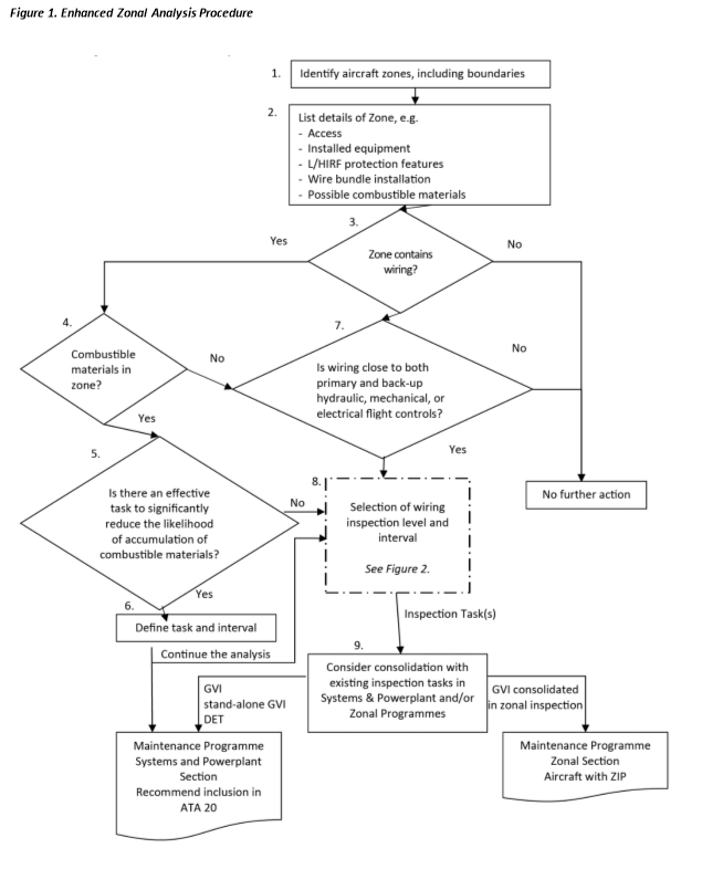
The following paragraphs provide further explanation of each step in the Enhanced Zonal Analyses Procedure logic, (Figures 1 and 2). It is recommended that, where possible, the analysts utilise the availability of actual aircraft to ensure they fully understand the zones being analysed. This will aid in determination of density, size, environmental issues, and accidental damage issues.
Step 1 “Identify aircraft zones, including boundaries”
The system consists of Major Zones, Major Sub Zones and Zones.
The zones, wherever possible, shall be defined by actual physical boundaries such as wing spars, major bulkheads, cabin floor, control surface boundaries, skin, etc. and include access provisions for each zone.
If the type design holder or operator has not yet established aircraft zones, it is recommended that it does so. Whenever possible, zones should be defined using a consistent method such as ATA iSpec 2200 (formerly ATA Spec 100), varied only to accommodate particular design constructional differences.
Step 2 “List of details of zone”
An evaluation will be carried out to identify system installations, significant components, L/HIRF protection features, typical power levels in any installed wiring bundles, combustible materials (present or possible accumulation), etc.
With respect to power levels the analyst should be aware whether the bundle consists primarily of main generator feeder cables, low voltage instrumentation wiring or standard bus wiring. This information will later be used in determining the potential effects of deterioration.
The reference to combustible materials highlights the need to assess whether the zone might contain material/vapour that could cause a fire to be sustained in the event of an ignition source arising in adjacent wiring. Examples include the possible presence of fuel vapours, dust/lint accumulation and contaminated insulation blankets. See also under Step 4 for further information.
For aircraft types whose design directives may not have excluded the possibility of inadequate segregation between systems, the analyst should identify locations where both primary and back-up flight controls are routed within 2 inches/50 mm of a wiring harness. This information is required to answer the question in Step 7.
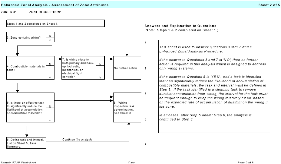
Step 3 “Zone contains wiring?”
This question serves as a means to eliminate from the EZAP those zones that do not contain any wiring.
Step 4 “Combustible materials in zone?”
This question requires an evaluation of whether the zone might contain combustible material that could cause a fire to be sustained in the event of an ignition source arising in adjacent wiring. Examples include the possible presence of fuel vapours, dust/lint accumulation, and contaminated insulation blankets.
With respect to commonly used liquids (e.g., oils, hydraulic fluids, corrosion prevention compounds) the analyst should refer to the product specification in order to assess the potential for combustibility. The product may be readily combustible only in vapour/mist form and thus an assessment is required to determine if conditions might exist in the zone for the product to be in this state.
Although liquid contamination of wiring by most synthetic oil and hydraulic fluids (e.g. skydrol) may not be considered combustible, it is a cause for concern if it occurs in a zone where it causes significant adherence of dust and lint.
The analyst should assess what sources of combustible products may contaminate the zone following any single failure considered likely from in-service experience. Unshrouded pipes having connections within the zone should be considered as potential contamination sources. Inherent ventilation in the zone should be taken into account when determining the potential for subsequent combustion. This influences the response to the question of how near to the harness the source should be for there to be a concern.
Avionics and instruments located in the flight compartment and equipment bays tend to attract dust, etc. In view of the heat generated by these components and the relatively tightly packed installations, the analyst should consider these zones as having potential for combustible material. Thus, the enhanced logic should always be used for these zones.
Note: Although moisture (whether clean water or otherwise) is not combustible, its presence on wiring is a cause for concern because it may increase the probability of arcing from small breaches in the insulation, which could cause a localised fire in the wire bundle. The risk of a sustained fire caused by moisture induced arcing is mitigated in Step 5 by identification of a task to reduce the likelihood of accumulation of combustible material on or adjacent to the wiring.
Step 5 “Is there an effective task to significantly reduce the likelihood of accumulation of combustible materials?”
Most operator maintenance programmes have not included tasks directed towards removal or prevention of significant accumulations of combustible materials on or adjacent to wiring.
This question requires an evaluation of whether the accumulation on or adjacent to wiring can be significantly reduced. Task effectiveness criteria should include consideration of the potential for damaging the wiring.
Though restoration tasks (e.g., cleaning) are the most likely applicable tasks, the possibility to identify other tasks is not eliminated. A detailed inspection of a hydraulic pipe might be assessed as appropriate if high-pressure mist from pinhole corrosion could impinge a wire bundle and the inherent zone ventilation is low.
Step 6 “Define task and interval”
This step will define an applicable task and an effective interval. It should be included as a dedicated task in the Systems and Powerplant section. Within Maintenance Review Board (MRB) Reports, this may be introduced under ATA 20 with no Failure Effect Category quoted.
It is not the intent that restoration tasks should be so aggressive as to damage the wiring, but should be applied to a level that significantly reduces the likelihood of combustion.
Step 7 “Is wiring close to primary and back-up hydraulic, mechanical, or electrical flight controls?”
Where wiring is close (i.e. within 5 cm (2 inches)) to both primary and back-up hydraulic, mechanical, or electrical flight controls, this question is asked to ensure that Step 8 logic is applied even in the absence of combustible materials in the zone.
For zones where combustible materials are present (as determined in Step 4), proximity is addressed in the inspection level definition portion of Step 8 and this question need not be asked.
It addresses the concern that segregation between primary and back-up flight controls may not have been consistently achieved. Even in the absence of combustible material, a localised wire arcing could impact continued safe flight and landing if hydraulic pipes, mechanical cables, or wiring for fly-by-wire controls are routed in close proximity (i.e. within 5 cm (2 inches)) to a wiring harness. In consideration of the redundancy in flight control systems, the question needs to be answered ‘Yes’ only if both the primary and back-up system might be affected by wire arcing. Note that in zones where a fire might be sustained by combustible material the enhanced logic will automatically be followed.
On all aircraft type designs, irrespective of TC date, modifications may not have taken into account the TC holder’s design and installation criteria. It is thus recommended that STC holders assess their design changes with this question included in the logic unless they can demonstrate that they followed equivalent installation criteria. Similarly, air carriers and air operators will have to assess modifications that have been accomplished on their aircraft.
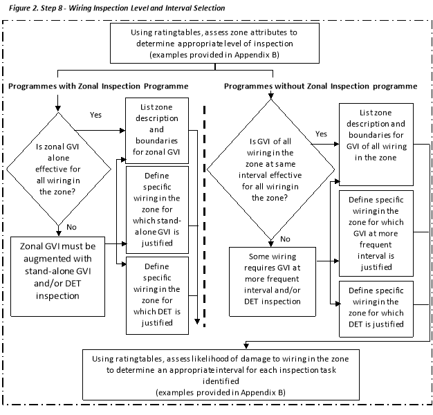
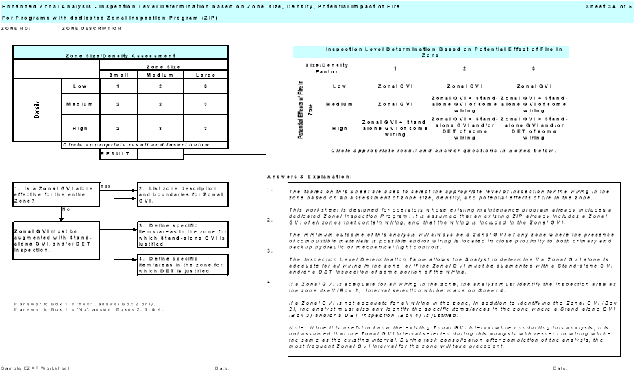
Step 8 “Selection of Wiring Inspection Level and Interval”
a. Inspection Level.
At this point in the analysis, it is already confirmed that wiring is installed in a zone where the presence of combustible materials is possible and/or the wiring is in close proximity to primary and back-up hydraulic or mechanical flight controls. Therefore, some level of inspection of the wiring in the zone is required, and this step details how the proper level of inspection and interval can be selected.
One method of selecting the proper inspection level and interval is through the use of ratings tables which rate attributes of the zone and how the wiring is affected by, or can affect those attributes. The precise format of this will be determined by the analyst, but example rating tables appear in Appendix B and may be referred to for clarity.
The inspection level characteristics that may be included in the rating system are:
— Zone size (volume);
— Density of installed equipment within the zone;
— Potential effects of fire on adjacent wiring and systems.
Zone size will be assessed relative to the size of the aircraft, typically identified as small, medium or large. The smaller the zone and the less congested it is, the more likely it is that wiring degradation will be identified by GVI.
Density of installed equipment, including wiring, within the zone will be assessed relative to the size of the zone. The density of the zone is typically identified as low, medium or high.
Potential effects of fire on adjacent wiring and systems requires the analyst to assess the potential effect of a localised fire on adjacent wiring and systems by considering the potential for loss of multiple functions to the extent that continued safe operation may not be possible.
Consideration of potential effect must also include whether wiring is in close proximity (i.e. within 5 cm (2 inches)) to both primary and back-up flight controls. A GVI alone may not be adequate if a fire caused by failure of the wiring poses a risk to aircraft controllability.
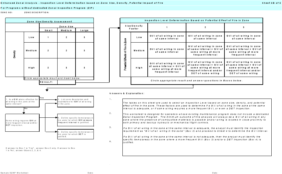
At minimum, all wiring in the zone will require a GVI at a common interval. For operators with a ZIP, this may be defined as a zonal GVI. For operators without ZIP, it shall be defined as a GVI of all wiring in the zone.
The question is asked, "Is a GVI (or zonal GVI) of all wiring in the zone at the same interval effective for all wiring in the zone?" This is to consider if there are specific items/areas in the zone that are more vulnerable to damage or contamination and thus may warrant a closer or more frequent inspection.
This determination could result in the selection of a more frequent GVI, a stand-alone GVI (for operators with a ZIP), or even a DET inspection. The intention is to select a DET of wiring only when justified by consideration of all three characteristics of the zone (size, density, and potential effect of fire). The analyst should be cautious to avoid unnecessary selection of DET where GVI is adequate. Over-use of DET dilutes the effectiveness of the inspection.
Note: The level of inspection required may be influenced by tasks identified in Steps 5 and 6. For example, if a cleaning task was selected in Step 5 and 6 that will minimise the accumulation of combustible materials in the zone, this may justify selection of a GVI in lieu of a DET for the wiring in the zone.
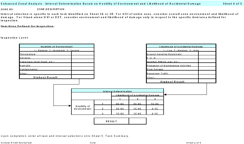
b. Inspection Interval.
The selection of an effective interval can also be accomplished using a rating system. The characteristics for wiring to be rated should include the following:
— Possibility of Accidental Damage;
— Environmental factors.
The rating tables should be designed to define increasing inspection frequency with increasing risk of accidental damage and increasing severity of the local environment within the zone. Examples are provided in Appendix E.
The selection of inspection tasks possible in this step is specific to whether the maintenance programme includes a dedicated ZIP or not.
For ZIP programmes, the possible inspection tasks are:
— Zonal GVI;
— Stand-alone GVI;
— DET.
For non-ZIP programmes, the possible inspection tasks are:
— GVI;
— DET.
Note: At this point the analyst will have determined the required inspection level and interval for wiring in the zone. Task consolidation in Step 9 allows consideration as to whether an inspection selected as a result of this analysis can be considered accomplished as part of the existing maintenance programme.
Step 9 “Task Consolidation”
This step in the procedure examines the potential for consolidation between the tasks derived from the EZAP and inspections that already exist in the Maintenance Programme. Consolidation requires that the inspections in the existing maintenance programme are performed in accordance with the inspection definitions provided in this AMC.
For programmes that include a ZIP:
Some GVI identified by application of the EZAP may be adequately covered by existing zonal GVI in the zone and no change or addition to the existing zonal GVI is required. This should reduce the number of new GVI that must be introduced into a programme that already includes a ZIP.
The consolidation of GVI tasks has to take into account the access requirements and the interval of each task. The Working Group may conclude that a stand-alone GVI of the wiring may be justified if the zonal GVI of the other systems within the same zone does not need to have such a frequent inspection.
Stand-alone GVI and DET identified by application of EZAP cannot be consolidated into the ZIP and must be introduced and retained as dedicated tasks in the scheduled maintenance programme under ATA 20. These tasks, along with tasks identified to reduce the accumulation of combustible materials, shall be uniquely identified to ensure they are not consolidated in the zonal programme nor deleted during future programme development. Within MSG-3 based MRB Reports, these may be introduced under ATA 20 with no Failure Effect Category quoted.
For programmes without a ZIP:
Although non-ZIP programmes may already include some dedicated inspections of wiring that may be reviewed for equivalency to new tasks identified by application of the EZAP, it is expected that a significant number of new wiring inspections will be identified for introduction as dedicated tasks in the System and Powerplant programme. All new tasks identified by application of EZAP shall be uniquely identified to ensure they are not deleted during future programme development.
The following guide can be used to determine proper consolidation between EZAP derived inspections and existing inspections that have not been specifically identified as stand-alone tasks, of the same item or area:
a. Where the EZAP inspection interval and existing inspection interval are equal, but the inspection levels are different, the more intense inspection will take precedent (i.e. a 1C DET takes precedent over a 1C GVI).
b. Where the EZAP inspection interval and existing inspection interval are different, but the inspection levels are equal, the more frequent inspection will take precedent (i.e. a 1C GVI takes precedent over a 2C GVI).
c. Where the EZAP inspection interval and level are different from the existing inspection interval and level, these tasks may be consolidated only when the more frequent inspection is also the more intense (i.e. a 1C DET takes precedent over a 2C GVI). When the more frequent inspection is less intense, the tasks should not be consolidated.
For all programmes, these tasks shall be uniquely identified in the programme for future development consideration.
For EZAP-derived STC tasks, it may not be possible for the STC holder to determine whether a ZIP exists on specific aircraft that will utilise the STC. Therefore, where a ZIP exists, consolidation of EZAP-derived STC tasks into a specific operator’s ZIP will be the responsibility of the operator and subject to approval by the competent authority.
In cases where the STC holder determines a requirement for a GVI that should not be consolidated into a ZIP, this stand-alone GVI should be specifically identified as such in the EZAP derived ICAW for the STC.
[Amdt 20/4]
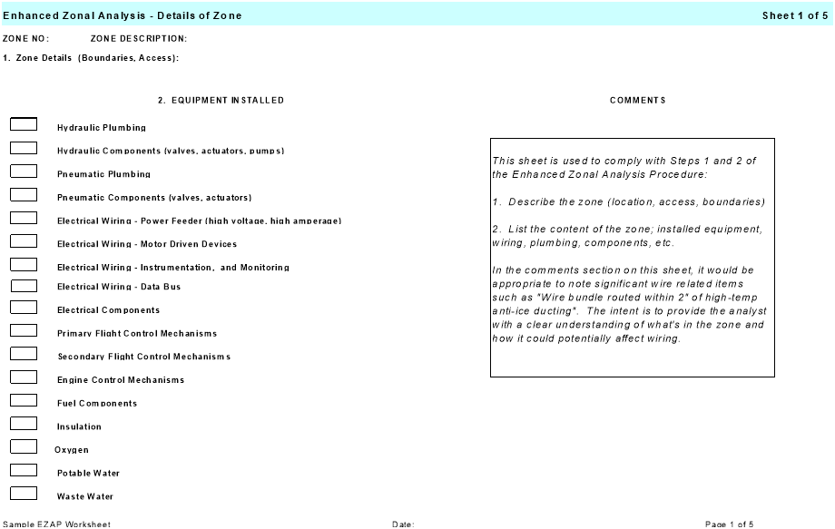
Appendix B to AMC 20-21 Examples of Typical EZAP Worksheets
ED Decision 2008/007/R
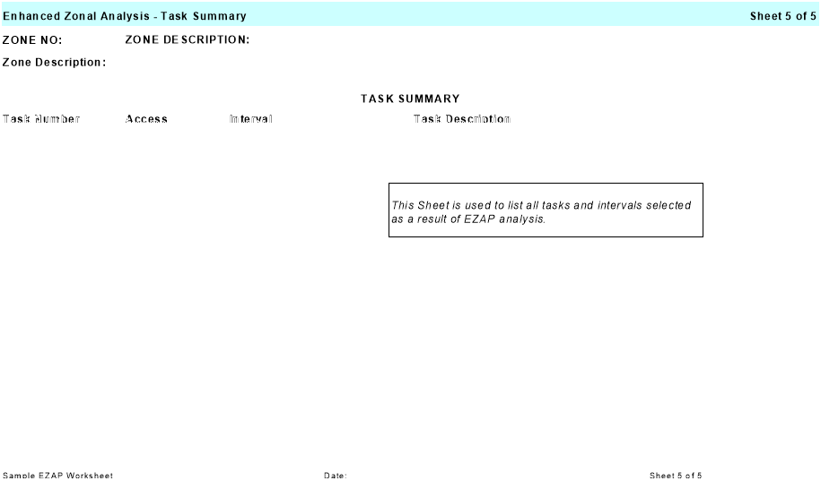
The following worksheets are provided as an example to assist implementation of the EZAP logic explained in this AMC. These may be adjusted by the analyst to suit specific applications.
1. Details of Zone.
2. Assessment of Zone Attributes.
3A. Inspection Level Determination based on Rating Tables (for use where a dedicated ZIP exists).
3B. Inspection Level Determination based on Rating Tables (for use where no dedicated ZIP exists).
4. Interval Determination based on Rating Tables.
5. Task Summary.
In particular, the interval ranges quoted in the rating table on Sheet 4 are solely to explain a typical arrangement of values. For a particular application, these must be compatible with the interval framework used in the existing maintenance or inspection programme. They may be expressed in terms of usage parameter (e.g. flight hours or calendar time) or in terms of letter check (as in the example).
[Amdt AMC/4]
Appendix C to AMC 20-21 Determination if a major change to an aircraft should be specifically subjected to an EZAP
ED Decision 2008/007/R
The EZAP provides a means for TC and STC holders to develop improvements to EWIS maintenance programs. These improvements will be in the form of new inspections and other tasks designed to prevent significant accumulation of combustible materials on or adjacent to EWIS components that would be added to the Instructions for Continued Airworthiness or Service Bulletins (SB) for the aircraft and STC.
While TC holders are required to conduct the EZAP for all zones in an aircraft, it may be determined that EZAP for an SB or STC is not necessary where the modification does not appreciably affect the zones where it is installed. The “Determination if SB modification or STC requires EZAP” procedure was developed to identify modifications that sufficiently affect zone attributes to warrant re-application of EZAP to the entire zone.
This logic assumes that the aircraft TC holder has accomplished the EZAP on each zone of the aircraft without consideration of the SB modification or STC installation. The objective of this analysis is to assess whether the modification itself has affected wiring or certain zone attributes that could change the outcome of the EZAP performed by the aircraft TC holder.
The determination if the SB or STC requires EZAP, and re-application of the EZAP to SB or STC affected zones, is the responsibility of the respective holder of the SB or STC. It is expected that the TC and STC holders will collaborate with each other and operators as necessary to obtain information required to conduct the analysis. The TC or STC holder should communicate the results of the procedure, including the cases when no new tasks are identified. The method of communication may be via SB, Service Letter, ICAW Revision, or other means acceptable to EASA.
In situations where a previously installed STC is no longer supported by a viable STC holder (e.g. STC holder defunct), the responsibility for determining if the STC requires EZAP, and re-application of EZAP to any affected zones, is assigned to the individual operators who utilise the STC on their aircraft. In cases where the operator does not have experience in application of analytical logic processes, it will be necessary for the operator to gain competence in, or seek external assistance in conducting the analysis.
A record of the outcome of operator accomplished analysis for STC (even if no tasks are identified) should be permanently retained by the operator. A copy of the record should be included in the aircraft records normally transferred upon change of aircraft operator.
The attached logic chart provides a means to assess whether an SB modification or STC has sufficiently affected wiring or certain other zone attributes as to require reapplication of the EZAP to the entire zone with consideration of the modification present. The section following the chart provides detailed explanations of each step in the “Determination if SB modification or STC requires EZAP” with appropriate examples.
It is recommended that, where possible, the analyst should utilise the availability of actual aircraft to ensure they fully understand the zones being analysed. Specifically, it must be determined how installation of the modification could affect zone attributes such as density, environment, proximity of wiring to primary and back-up flight controls, presence of combustible materials, and potential for accidental damage to wiring.
Appendix C. Figure 1. Determination if SB modification or STC requires EZAP
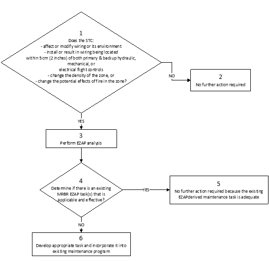
Explanation of Steps
Step 1: Does the SB or STC affect or modify wiring or it’s environment?
The question asks whether the STC affects or modifies wiring. Modifications to wiring or other EWIS components include, but are not limited to removal, addition, relocation, etc.
Does the SB or STC install or result in wiring being located within 5 cm (2 inches) of primary and back-up hydraulic, mechanical or electric flight controls, change the density of the zone or change the potential effects of fire in the zone?
Does the SB or STC affect zone density? If the STC includes the addition or deletion of numerous components in a small area, the density of the zone could be changed even if wire bundles are untouched. A significant change in the zone density should warrant re-analysis of the zone.
Potential effects of fire on adjacent wiring and systems require the analyst to assess the potential effect of a localised fire on adjacent wiring and systems by considering the potential for loss of multiple functions to the extent that a hazard could be introduced. Consideration of potential effect must also include whether wiring is in close proximity (i.e. within 5 cm (2 inches)) to both primary and back-up flight controls.
Additionally, this question requires an evaluation of whether the zone might contain combustible material that could cause a fire to be sustained in the event of an ignition source arising in adjacent wiring. Examples include the possible presence of fuel vapours, dust/lint accumulation, and contaminated insulation blankets.
With respect to commonly used liquids (e.g. oils, hydraulic fluids, and corrosion prevention compounds), the analyst should refer to the product specification in order to assess the potential for combustibility. The product may be readily combustible only in vapour/mist form and thus an assessment is required to determine if conditions might exist in the zone for the product to be in this state.
Although liquid contamination of wiring by most synthetic oil and hydraulic fluids (e.g. skydrol) may not be considered combustible, it is a cause for concern if it occurs in a zone where contamination causes significant adherence of dust and lint.
If the answer to this question is ‘No’, then no further action is required (Step 2), since the density of the zone or the potential effects of fire in the zone has not changed.
Step 2: No further action is required.
Step 3: Perform an EZAP analysis.
If the answer to question 1 is ‘Yes’, then the only way to determine if existing EWIS maintenance tasks are sufficient is to perform the EZAP for the SB or STC and compare the results with the existing EWIS maintenance tasks (see Step 4).
Step 4: Is there an existing MRBR EZAP task(s) that is applicable and effective?
Once the SB or STC EZAP has been accomplished, a comparison of the derived maintenance tasks can be made with the existing EWIS maintenance tasks. If the existing tasks are adequate, then no further action regarding EWIS maintenance actions for the STC is necessary.
Step 5: No further action is required since the existing EZAP-derived maintenance task is adequate.
Step 6: Develop an appropriate task and incorporate it into the existing maintenance programme.
These tasks should be incorporated into the operator’s existing maintenance programme.
[Amdt 20/4]
ED Decision 2008/007/R
(RESERVED)
Appendix E to AMC 20-21 Causes of Wire Degradation
ED Decision 2008/007/R
The following items are considered principal causes of wiring degradation and should be used to help focus maintenance programmes:
Vibration - High vibration areas tend to accelerate degradation over time, resulting in “chattering” contacts and intermittent symptoms. High vibration of tie-wraps or string-ties can cause damage to insulation. In addition, high vibration will exacerbate any existing problem with wire insulation cracking.
Moisture - High moisture areas generally accelerate corrosion of terminals, pins, sockets, and conductors. It should be noted that wiring installed in clean, dry areas with moderate temperatures appears to hold up well.
Maintenance - Scheduled and unscheduled maintenance activities, if done improperly, may contribute to long-term problems and wiring degradation. Certain repairs may have limited durability and should be evaluated to ascertain if rework is necessary. Repairs that conform to manufacturers recommended maintenance practices are generally considered permanent and should not require rework. Furthermore, care should be taken to prevent undue collateral damage to EWIS while performing maintenance on other systems.
Metal shavings and debris have been discovered on wire bundles after maintenance, repairs, modifications, or STC have been performed. Care should be taken to protect wire bundles and connectors during modification work. The work areas should be cleaned while the work progresses to ensure that all shavings and debris are removed; the work area should be thoroughly cleaned after the work is complete; and the work area should be inspected after the final cleaning.
Repairs should be performed using the most effective methods available. Since wire splices are more susceptible to degradation, arcing, and overheating, the recommended method of repairing a wire is with an environmental splice.
Indirect Damage - Events such as pneumatic duct ruptures or duct clamp leakage can cause damage that, while not initially evident, can cause wiring problems at a later stage. When events such as these occur, surrounding EWIS should be carefully inspected to ensure that there is no damage or no potential for damage is evident. The indirect damage caused by these types of events may be broken clamps or ties, broken wire insulation, or even broken conductor strands. In some cases the pressure of the duct rupture may cause wire separation from the connector or terminal strip.
Contamination - Wire contamination refers to either of the following situations:
a. The presence of a foreign material that is likely to cause degradation of wiring.
b. The presence of a foreign material that is capable of sustaining combustion after removal of ignition source.
The contaminant may be in solid or liquid form. Solid contaminants such as metal shavings, swarf, debris, livestock waste, lint and dust can accumulate on wiring and may degrade or penetrate wiring or electrical components.
Chemicals in fluids such as hydraulic fluid, battery electrolytes, fuel, corrosion inhibiting compounds, waste system chemicals, cleaning agents, de-icing fluids, paint, soft drinks and coffee can contribute to degradation of wiring.
Hydraulic fluids, de-icing fluids and battery electrolyte require special consideration. These fluids, although essential for aircraft operation, can damage connector grommets, wire bundle clamps, wire ties and wire lacing, causing chafing and arcing. Wiring exposed to these fluids should be given special attention during inspection. Contaminated wire insulation that has visible cracking or breaches to the core conductor can eventually arc and cause a fire. Wiring exposed to, or in close proximity to, any of these chemicals may need to be inspected more frequently for damage or degradation.
When cleaning areas or zones of the aircraft that contain both wiring and chemical contaminants, special cleaning procedures and precautions may be needed. Such procedures may include wrapping wire and connectors with a protective covering prior to cleaning. This would be especially true if pressure-washing equipment is utilised. In all cases the aircraft manufacturer recommended procedures should be followed.
Waste system spills also require special attention. Service history has shown that these spills can have detrimental effects on aircraft EWIS and have resulted in smoke and fire events. When this type of contamination is found all affected components in the EWIS should be thoroughly cleaned, inspected and repaired or replaced if necessary. The source of the spill or leakage should be located and corrected.
Heat - Exposure to high heat can accelerate degradation of wiring by causing insulation dryness and cracking. Direct contact with a high heat source can quickly damage insulation. Burned, charred or even melted insulation are the most likely indicators of this type of damage. Low levels of heat can also degrade wiring over a longer period of time. This type of degradation is sometimes seen on engines, in galley wiring such as coffee makers and ovens, and behind fluorescent lights, especially the ballasts.
[Amdt 20/4]